Design and Implementation of Artificially Intelligent
Microcontroller based Chess Opponent
Gurjit Kaur, Anil K. Yadav, Varun Anand
Abstract— This project is an attempt to design an Artificially Intelligent Microcontroller based Chess Opponent (MAICO) which can compete against the user and calculate its moves. In this work, a chess playing system has been designed which implements an interface allowing a computer to control chess movements using PC’s parallel port and AT89C51. It is a fully automated system integrated with microcontrollers, camera, and Artificially Intelligent agent. Various algorithms are implemented for interfacing hardware in C and MATLAB. In this paper we have aimed to design a cost effective robot that consumes minimal amount of power.
Index Terms— Binary Image, MAICO, Pixel, RAM, RGB Image
I. INTRODUCTION
Chess is a well known board game also known as Shatranj originated in India, a game played between two players and can be played for long hours. But in today’s world people have very less time and thus the chess lovers have to satisfy themselves by playing against the computer which leads to sore eyes and other health problems. All this led to development of various strategies that have been developed by theoreticians in the past to create a design which appears to be realistic and can be a better replacement for human opponent.
The work done on this earlier by researchers used complex electrical circuit chess boards [1] or fancy hardware which has made the game even more tedious and added to more of the cost using the hardware design, but in our research work we have made it more user friendly, cost effective and at the same time power efficient. The main focus of the project is to design a system that can play the actual game by analyzing the human moves and generate counter moves.
Manuscript received March 18th, 2010. This work was supported by
Electronics and Communication Engineering Department of Jaypee Institute of Information Technology, Noida, UP, India.
Gurjit Kaur is working as a Senior Lecturer in ECE department of Jaypee Institute of Information Technology, Noida, India. email: [email protected], [email protected]
Author Anil Kumar Yadav is with ECE Department of Jaypee Institute Of Information Technology University, Noida, UP, India, email- [email protected]
Author Varun Anand is with ECE Department of Jaypee Institute of Information Technology University, Noida, UP, India Email- [email protected]
II. DESIGN
The basic work flow diagram of MAICO is show below in Fig1.
Fig1. Working principle of MAICO
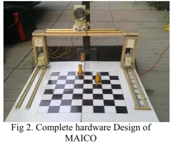
[image:1.595.333.506.408.556.2]Fig 2. shows the complete hardware design of MAICO without a camera mounted at the top. We have divided the design section in following modules.
Fig 2. Complete hardware Design of MAICO
A. Hardware Implementation Module
The hardware module applies computer’s moves against the human opponent which includes mechanical design of the robot, chessboard and the chess pieces.
B. Vertical Section
Fig. 3(a) shows the vertical section which has two DC geared motors of 12V, 850mA. They have been further modified using gears and wooden pieces to carry horizontal section over it. These two motors run along the opposite sides of the chess board on two parallel tracks to access the particular rank (Y-AXIS).
C. Horizontal Section
(X-AXIS) and runs on two parallel tracks. The upper motor is used to pick and drop the chess coins using electromagnet which is attached to the motor via pulley.
Fig.3 (a) Vertical Motor Fig.3(b) Horizontal Motor
D. Chessboard and Chess Pieces
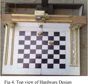
[image:2.595.67.275.129.265.2]Chessboard is a square board having eight rows and eight columns of 4cm x 4cm each.
Fig 4. Top view of Hardware Design
Chess pieces are specially designed having equal heights and broader base. In order to pick the chess pieces by the electromagnet, there is a circular iron ring on the top of chess pieces. The top view of hardware of MAICO is shown in fig.4
E. Electrical Design Module
Electrical design comprises mainly of
[image:2.595.329.528.258.410.2]microcontroller, motor driving ICs and electrical sensors. Fig.5 shows the signal flow between above mentioned components.
Fig 5. Block Diagram of Electrical Design Module
F. Microcontroller
We have used microcontroller which takes input from parallel port and controls the motor driving IC by giving control signals to it. At the same time, the movement of bot is continuously monitored using electrical sensors. The microcontroller used is Atmel’s AT89C51 [2]. It is an 8-bit microcontroller with 4KB flash, 128 bytes of ram, two 16-bit timers/counters and 32 programmable I/O lines.
G. Motor Driving IC
For motor driving we have used two L293D[3] which can provide bidirectional drive currents of up to 600mA at voltages from 4.5V to 36V.
Fig 6(a). DC Motor control connections
Fig 6(b). Truth Table for Motor Controls
This IC controls the robot movement in both forward and backward directions in accordance with the control signals sent by the microcontroller. Its connection diagram and truth table are shown in fig.6.
H. Electrical Sensors
[image:2.595.101.251.328.471.2] [image:2.595.348.508.446.554.2] [image:2.595.48.264.631.675.2]Fig 7. Electrical Sensors
III. SOFTWARE MODULE
Aim of this section is to design and implement various algorithms which can interact with the hardware and helps in achieving the objective. It’s similar to providing eyes and brain to a machine. Software designing is done in C and MATLAB as coding can easily be done in these two languages.
In the project, developed software helps the robot to understand the opponents move and to generate a counter move. To achieve above target the module is divided into following sections.
A. Image Acquisition
In this section we have written a MATLAB code which captures a RGB image of chessboard with the help of a camera mounted at the top of the board. The resolution of image, format type and intensity is set as per the requirement.
There is an LED which is user controlled whenever he/she is ready. Images are captured continuously with a small time interval between the two consecutive images. These captured images are than passed through a code to check whether the LED in the images is ON/OFF. If LED in the image is ON, then it means user has made his move and thus the captured image is stored and further
used for image processing.
B. Image Processing
In this section the captured images are subjected to various algorithms to detect the moves played by human or computer and also to detect location of various chess pieces. With the help of algorithm a matrix is formed to give the actual location of chess pieces on chessboard. This is explained further in following sections.
a) ChessBoard Cropping
For further computation, we needed to crop the original image and extract only the chessboard. This is done using edge detection[4] and pixel identification. Once the diagonally opposite coordinates of the chessboard are detected, the image can be cropped and stored for move detection. Fig 8 shows the cropped image of chessboard.
Fig 8. Cropped Image of the Chess Board
b) Move Detection
We have used MATLAB to detect the move played by user. For this following steps are performed.
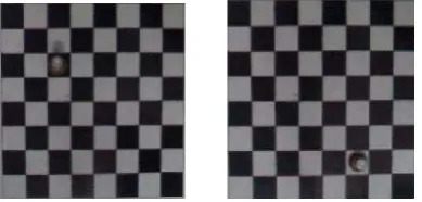
STEP 1 [A] =Image01 [B] =Image02
Image01 and Image02 are images taken before and after the human played his turn. Fig.9 shows these two images respectively.
Fig 9. Images showing chess pieces at different coordinates
STEP 2 [X1] = [A] - [B] [X2] = [B] - [A] [X] = [X1] + [X2]
[X] is a RGB matrix[5] that contains all the necessary information required for move detection.
STEP 3
[X] is converted to a binary matrix [B]. During this some noise gets added because of intensity variation and shadow effect. This binary image with noise can be seen in Fig.10
[image:3.595.312.507.348.441.2][image:3.595.364.478.622.742.2]
STEP 4
[image:4.595.111.220.219.299.2]Binary matrix is passed through a special filter[6] to sharpen the image and Noise filter which is shown in Fig 11
Fig 11.Noise filter which compares all the pixels with surrounding pixels
[image:4.595.315.538.325.540.2]STEP 5
[image:4.595.115.223.357.464.2]Fig.12 shows the noise free Binary image. This is then further divided in 8X8 blocks having elements (e) of value 1 or 0.
Fig 12 Binary Image after passing through Noise Filter
STEP 6
[image:4.595.54.258.548.669.2]Each element of a block is summed up and stored in a coordinate matrix to make a 8X8 co-ordinate matrix.
[Coordinate]8X8 = [∑i,j e] The matrix generated for Fig.12 is shown in Fig.13
.
Fig 13Co-ordinate matrix generated by move detection code.
The algorithm designed for noise and shadow removal is fast and easy comparing to algorithms used earlier. The detected coordinates are then stored in a text file, which is used later by an AI agent.
IV. AIAGENT
The AI (Artificial Intelligence) agent is the brain of our chess robot. It generates computer’s moves against a human opponent by predicting future moves and calculating various risks.
V. INTERFACING OF MODULES
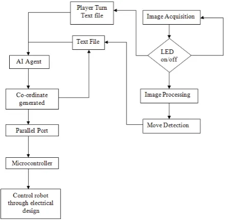
There are two types of interfacing that is required in our project. First is the software – hardware interfacing which is required to control robot. This interfacing is done using parallel port. The signals from computer are sent to microcontroller using parallel port. Second interfacing is software – softwareinterfacing, which is between AI agent code (in C language) and image processing code (in MATLAB). Fig.14 shows complete flowchart of Software design of MAICO.
Fig 14 Flow chart representation of MAICO
A. Design Specifications
Coordinate System Cartesian
Motor Type DC geared
No of Motors 4
Movement X, Y, Z axis
Sensors Electrical Sensors
Software C language,
MATLAB
Length 50cm Breadth 50cm Height 1m
Power Supply 12V DC,2A / 5V DC,1A
Microcontroller ATMEL’S AT89C51
Interfacing 8-bit Parallel port
Motor Driving IC L293D
Others Electromagnet,
Camera(2MP)
VI. CONCLUSION
This paper gives an idea to implement a high level design of artificially intelligent robot to play chess in real time environment. We have successfully implemented the above described design and tested it in real time scenario. Hardware implementation is in such a way which makes it very easy to carry the project and assemble anywhere without prior technical skills.
The algorithms used are simple and fast from the perspective of computation and can be used for educational purposes.
REFERENCES
[1] Arun Kumar N, Sandeep Kumar KG and Varun Kumar K,
“CHESSBOT – A chess playing robot”, Thesis, Dept. of Electrical and electronics Engineering, Pondicherry Engineering College,
Pondicherry.
[2] Microcontroller ATMEL AT89C51, www.atmel.com/atmel. [3] IC-L293D , http://www.datasheetcatalog.com/datasheets_
pdf/L/2/9/3/L293D.shtml
[4] John Canny, “A Computational Approach to Edge Detection”, IEEE transaction on Pattern Analysis and Machine Intelligence 1986, Volume-8, Issue-6.
[5] Gonzalez, R. and Woods, R., Digital Image Processing, Second