warwick.ac.uk/lib-publications
Original citation:
Ronak, Bajaj and Fahmy, Suhaib A.(2016) Mapping for maximum performance on FPGA DSP
blocks. IEEE Transactions on Computer-Aided Design of Integrated Circuits and Systems, 35
(4). pp. 573-585.
Permanent WRAP URL:
http://wrap.warwick.ac.uk/77879
Copyright and reuse:
The Warwick Research Archive Portal (WRAP) makes this work by researchers of the
University of Warwick available open access under the following conditions. Copyright ©
and all moral rights to the version of the paper presented here belong to the individual
author(s) and/or other copyright owners. To the extent reasonable and practicable the
material made available in WRAP has been checked for eligibility before being made
available.
Copies of full items can be used for personal research or study, educational, or not-for profit
purposes without prior permission or charge. Provided that the authors, title and full
bibliographic details are credited, a hyperlink and/or URL is given for the original metadata
page and the content is not changed in any way.
Publisher’s statement:
“© 2016 IEEE. Personal use of this material is permitted. Permission from IEEE must be
obtained for all other uses, in any current or future media, including reprinting
/republishing this material for advertising or promotional purposes, creating new collective
works, for resale or redistribution to servers or lists, or reuse of any copyrighted component
of this work in other works.”
A note on versions:
The version presented here may differ from the published version or, version of record, if
you wish to cite this item you are advised to consult the publisher’s version. Please see the
‘permanent WRAP url’ above for details on accessing the published version and note that
access may require a subscription.
Mapping for Maximum Performance
on FPGA DSP Blocks
Bajaj Ronak,
Student Member, IEEE,
and Suhaib A. Fahmy,
Senior Member, IEEE
Abstract—The digital signal processing (DSP) blocks on modern field programmable gate arrays (FPGAs) are highly capable and support a variety of different datapath configurations. Unfortunately, inference in synthesis tools can fail to result in circuits that reach maximum DSP block throughput. We have developed a tool that maps graphs of add/sub/mult nodes to DSP blocks on Xilinx FPGAs, ensuring maximum throughput. This is done by delaying scheduling until after the graph has been partitioned onto DSP blocks and scheduled based on their pipeline structure, resulting in a throughput optimized implementation. Our tool prepares equivalent implementations in a variety of other methods, including high-level synthesis (HLS) for comparison. We show that the proposed approach offers an improvement in frequency of 100% over standard pipelined code, and 23% over Vivado HLS synthesis implementation, while retaining code portability, at the cost of a modest increase in logic resource usage.
Keywords—Datapath synthesis, digital signal processing (DSP), eld programmable gate arrays (FPGAs), fixed-point arithmetic.
I. INTRODUCTION
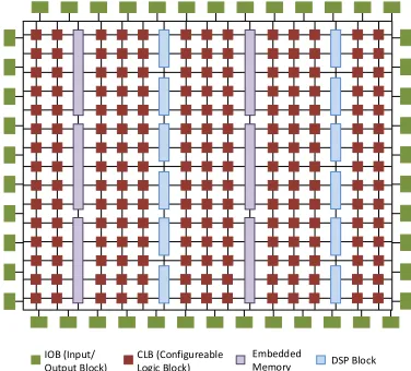
As FIELD PROGRAMMABLE GATE ARRAYS (FPGAs) have moved from being used in glue logic and interfacing to implementing complete systems, manufacturers have sought to improve their performance and efficiency. While the general look-up table (LUT)-based architecture offers generality, there are numerous functions that find widespread use across many different applications, and which, when implemented in LUTs consume significant area and power; arithmetic operators are an example. Hence, hard blocks have been added to FPGA architectures to make common functions more efficient than equivalent implementations in LUTs. FPGAs have found ap-plication in different areas like digital signal processing (DSP), image processing, software defined radio, automotive systems, high performance computing, security, and more, through the capabilities offered by embedded blocks like Block RAMs and DSP blocks. A general overview of the architecture of a modern Xilinx FPGA is shown in Fig. 1.
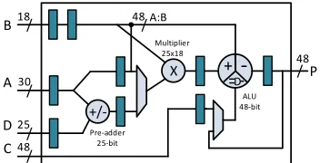
Xilinx first introduced hard multipliers in the Virtex-II family of FPGAs to speed up arithmetic computations. These evolved into the highly capable and flexible DSP48E1 blocks in recent Virtex-6 and 7-series devices. The DSP48E1 primi-tive supports many functions including add-multiply, multiply, multiply-accumulate, multiply add, and three-input add, which are selected through configuration inputs. Pipeline registers are also embedded within these blocks to enhance throughput. A simple representation of the DSP48E1 primitive is shown in Fig. 2. Inputs A, B, C, and D are of different wordlengths: 30, 18, 48, and 25 bits, respectively. The primitive’s three
IOB (Input/ Output Block)
CLB (Configureable Logic Block)
[image:2.612.350.538.153.323.2]Embedded Memory DSP Block
Fig. 1: Modern Xilinx FPGA architecture, showing different basic components.
sub-blocks are the preadder, multiplier, and arithmetic logic unit (ALU). The preadder is a 25-bit add/subtract unit which operates on input D and the lower 25 bits of input A. The multiplier block is 25×18 bits, multiplying the lower 25 bits of input A with input B. The ALU block is an add/subtract/logic unit which can operate on the multiplier output, input C, concatenated A and B inputs, or the previous output of the DSP block [1]. These sub-blocks can be combined in various ways to allow the DSP block to be used for different functions. Pipelined register transfer level (RTL) code can be mapped to DSP blocks when its structure is similar to one of the possible configurations. However, complex functions requiring multiple DSP blocks do not achieve performance close to the capabilities of the DSP blocks because the vendor tools fail to effectively map them to the DSP blocks. Our experiments show that mapping is primarily focused around using the multipliers in the DSP block, and often other operators are simply implemented in LUTs.
+/-+
-D
/
/
/ /
18
30
25
48
/
48
B
A
D C
P
Multiplier 25x18
Pre-adder 25-bit
X /
48 A:B
[image:3.612.87.263.54.144.2]ALU 48-bit
Fig. 2: Structure of the Xilinx DSP48E1 primitive.
the DSP48E1 primitives directly. We have also integrated the open-source tool Gappa [2] to allow us to investigate resulting truncation errors and optimise allocation of signals to the different DSP block inputs. The proposed mapping approach can be incorporated into a high-level synthesis flow to allow arithmetic-intensive inner loops to be mapped for maximum throughput.
We present an automated tool that can map complex mathe-matical functions to DSP blocks, achieving throughput close to the theoretical limit. Our focus is on exploiting the full capa-bilities of the DSP block while maintaining throughput through matched pipelining throughout the computational graph. A function graph is first segmented into sub-graphs that match the various possible configurations of the DSP block primitive, then balancing pipeline registers are inserted to correctly align the datapaths. We show that generic RTL mapped in this manner achieves identical performance to code that instantiates the DSP48E1 primitives directly. We have also integrated the open-source tool Gappa [2] to allow us to investigate resulting truncation errors and optimize allocation of signals to the different DSP block inputs. The proposed mapping approach can be incorporated into a high-level synthesis (HLS) flow to allow arithmetic-intensive inner loops to be mapped for maximum throughput.
The main contributions of this paper are:
1) A tool to segment complex mathematical expressions
across DSP blocks, considering their internal capabil-ities and pipeline registers, with both a greedy and improved heuristic method demonstrated.
2) Automation of mapping to a number of different
tech-niques, including pipelined RTL and Vivado HLS, to demonstrate the effectiveness of our approach.
3) Integration of Gappa error analysis for improved
map-ping to minimize error.
4) Full automation of the design flow for both the
pro-posed and comparison methods, allowing a thorough investigation of performance metrics.
5) Comparison of the proposed approach against others
for 18 benchmarks, as well as a case study application, demonstrating significant improvements in throughput.
II. RELATEDWORK
As DSP blocks can offer increased performance when mapping computationally intensive datapaths, many algorithms
have been implemented with careful mapping to these blocks. Examples include color space conversion [3], floating point operators [4], [5], filters [6], and cryptography [7], where the DSP blocks offer an overall increase in system performance over LUT-only implementations. This requires the datapaths to be manually tailored around the low-level structure of the DSP block, maximizing use of supported features. More general application to polynomial evaluation has also been proposed, again with detailed low-level optimization around DSP block structure [8]. The flexible DSP blocks in Xilinx FPGAs have also been exploited as the main functional unit in a soft processor [9].
While synthesis tools can infer DSP blocks from general pipelined RTL code, system design is increasingly being done at higher levels of abstraction. Widely used HLS tools today include Impulse-C [10], Bluespec [11], LegUp [12], and Xilinx Vivado HLS [13]. These tools synthesize to general RTL code which is then mapped through vendor tools to a specific target device. The main challenge here is that some optimizations made in the conversion to RTL may prevent efficient mapping to hard macros, especially when the functionality to be mapped is beyond the “standard” behavior of a single block. In a typical HLS flow, the datapath is extracted from the high-level description and scheduled before RTL is generated. This scheduling is architecture agnostic and primitives are inferred instead during the synthesis and mapping phases. Hence, if the schedule does not “fit” the structure of the DSP block, it may not be inferred to the fullest extent.
FloPoCo [14] is an open-source tool written in C++, that generates custom arithmetic cores using optimized floating-point operators, generating synthesisable VHSIC hardware de-scription language. It comprises a collection of parameterized basic operators and can be used to generate custom architec-tures satisfying user-defined constraints, including precision and target frequency. It also includes a polynomial function evaluator, which can implement arbitrary single- variable poly-nomial circuits. However, it generally uses DSP blocks as fast multipliers, and does not consider the other sub-blocks (preadder and ALU), except insofar as the synthesis tools infer them.
General mapping to hard blocks has been considered in various implementation flows. Verilog-to-Routing (VTR) [15] is an end-to-end tool which takes a description of a circuit in Verilog HDL and a file describing the architecture of the target FPGA and elaborates, synthesizes, packs, places, and routes the circuit, also performing timing analysis on the design after implementation. Its front-end synthesis is done using ODIN-II [16] which is optimized for some embedded blocks like multipliers and memories. For more complex embedded blocks, the user must explicitly instantiate them, and they are considered “black boxes” by the tool.
At present, there are no tools that automatically map to flexible, multifunction hard macro blocks efficiently because this is left to the mapping stage. We present a DSP block mapping flow that results in hardware implementations that operate at close to maximum frequency, while consuming comparable resources to HLS tools. This flow could be integrated into an HLS tool to allow its benefits to be gained in larger, more complex applications.
Gappa [2] is a tool intended for verification and formal proof generation on numerical expressions, supporting both fixed-point and floating-fixed-point arithmetic. It can generate tight bounds on computational errors at intermediate and output nodes, and can be used for output range determination for given input ranges. Tisserand [17], [18] used Gappa to determine tight bounds for datapath optimization and precision analysis for polynomial evaluation. Gappa and Gappa++ [19] were also used for dataflow computations functions precision analysis for SPICE simulations in [20]. We integrate Gappa in our flow to help improve the accuracy of the resulting implementations.
III. APPROACHES FORMAPPING TODSP BLOCKS
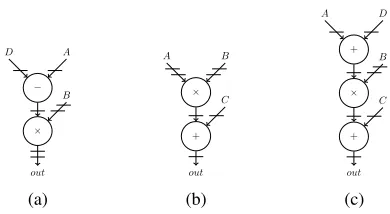
We consider graphs of add-multiply nodes typical of a wide range of algorithms. Recall that we are focused here on what would be the inner loop mapping for a typical HLS design. Ideally, these graphs can make use of the various sub-blocks present in the DSP48E1 primitive (Fig. 2) if mapped correctly, meaning extra LUT-based circuitry is reduced, and the resulting implementation should reach close to the DSP block maximum frequency of around 500 MHz (on the Virtex 6 family). The configuration inputs to DSP48E1 primitive determine how data passes through the block, and which sub-blocks are enabled. These configuration inputs can be set at run time, or fixed at design time. Considering all combinations of arithmetic operations, the DSP48E1 supports 29 different datapath configurations, which we store in a template database. Three of these are shown in Fig. 3. In addition to these 29 DSP block templates, we include a template for LUT-based parameterized adder/subtractor. The template database can also be expanded to include custom-designed optimized operators like dividers or wide multipliers. Note that such custom templates would be treated as black boxes, since they would already be optimized, hence not offering the flexibility we are exploiting in the DSP blocks. For this paper, we have limited our scope to add-multiply graphs to explore the limits of DSP block mapping.
Mapping an add-multiply graph to a circuit can be done in various ways. A simple and naive approach that fully relies on vendor tools, is to write combinational Verilog statements representing the required data flow, adding registers at the output, allowing the tools to redistribute these during retiming, with the mapping phase then inferring DSP blocks. Synthesis tools can generally map individual Verilog arithmetic operators efficiently. A more informed approach is to write a pipelined RTL implementation after scheduling the flow graph with pipeline registers added between arithmetic stages. Alternatively, the dataflow graph can be described in a high-level language and HLS tools used to map to a hardware implementation.
−
D A
×
B
out (a)
×
A B
+ C
out (b)
+
A D
×
B
+ C
[image:4.612.347.542.50.157.2]out (c)
Fig. 3: DSP48E1 configuration dataflow graphs for expressions (a)(D−A)×B, (b)C+ (A×B), and (c)C+ ((D+A)×B), where horizontal lines are registers.
Although none of these techniques take into account the internal structure of the DSP blocks, we expect the vendor mapping tool to efficiently utilize the different configurations of the DSP blocks in implementation. In the combinational implementation with retiming, we expect the synthesis tools to retime the design by absorbing the output registers into the datapath, allowing portions of graph to be mapped to the sub-blocks and pipeline stages of the DSP blocks. However, our experiments show that vendor tools do not retime deeply into the graph, resulting in DSP blocks being used only for multiplication.
In a scheduled pipelined RTL implementation, the operation schedule has been fixed and the tools have little flexibility to retime the design, but will nonetheless map to DSP block configurations when a set of operations and intermediate registers match. HLS tools generate a generic intermediate RTL representation, similar to manually scheduled pipelined RTL, though we might expect them to do this in a more intelligent manner when dealing with DSP blocks. Our ex-periments have shown that none of the above methods result in implementations that maximize DSP block usage or achieve high performance, as we discuss in Section VII.
Our proposed tool generates RTL code that maximizes performance through efficient mapping to FPGA DSP blocks. First, the arithmetic graph is segmented into sub-graphs that each match one of the DSP block configurations in the tem-plate database discussed earlier. The sub-graphs can then be converted to either direct instantiations of DSP48E1 primitives with the correct configuration inputs, or RTL representations of the same templates. While direct instantiation ensures the DSP blocks are adequately used, it makes the output code less portable and readable, and this might not be preferable where the graph is part of larger system. The tool creates alternative implementations from any given input graph and generates area and frequency results for comparison. We now discuss how these different techniques are implemented.
A. Combinational Logic with Re-timing: Comb
the register balancing Synthesis Process property in Xilinx ISE. Ideally, this should allow the tool to retime the design by pulling register stages back through the datapath to allow more efficient DSP block mapping.
B. Scheduled Pipelined RTL:Pipe
As soon as possible (ASAP) and as late as possible (ALAP) schedule variations are generated, with pipeline stages inserted between dependent nodes, mirroring what a typical RTL de-signer might do. Additional registers are added to ensure all branches are correctly aligned.
C. High-Level Synthesis:HLS
We use Vivado HLS from Xilinx because it is likely to be the most architecture aware of any of the HLS tools available. Similar to Comb, each node is implemented as an expression, and directives are used to guide the RTL implementation to fully pipeline the design. Since C++ code can have only one return value, dataflow graphs with multiple outputs are implemented by concatenating all the outputs, which can later be sliced to obtain individual outputs.
D. Direct DSP Block Instantiation:Inst
The dataflow graph is segmented into sub-graphs that can be mapped to one of the DSP48E1 templates identified earlier. Two graph segmentation approaches are explored. The first is a greedy approach, in which the graph is traversed from input to output with appropriate sub-graphs identified during traversal. The second approach applies a heuristic to try and fit as many nodes as possible into each sub-graph. Both of these methods are discussed in Section IV. For Inst, the determined sub-graphs are then swapped for direct instantiations of the DSP48E1 primitive, with all control inputs set to the required values.
E. DSP Block Architecture Aware RTL:DSPRTL
Rather than instantiating the DSP48E1 primitives directly, we replace each sub-graph with its equivalent RTL code directly reflecting the templates structure. This variation will make it clear if it is the instantiation of the primitives, or the structure of the graph that has a fundamental effect on performance.
F. Ensuring a Fair Comparison
Along with generating all five different implementations from the same graph description, a number of factors must be considered to ensure a fair comparison. The first is the overall latency of an implementation, as it impacts resource
requirements. Inst uses fully pipelined DSP blocks, which
results in a deep pipeline, and thus many balancing registers.
For Comb, we add as many pipeline stages after the
combi-national logic for retiming as there are pipeline stages in Inst. This gives the tools sufficient flexibility to retime the circuit up to an equivalent depth in theory. Similarly, for HLS, we enforce a constraint on latency, equal to the latency of Inst,
X
+/-D A
B
C
P
+/-+
-D
/
/
/
/ 48 25 30 18
/ 48
B
A
D
C
P
M
u
lti
p
lie
r
25
x18
P
re
-a
d
d
e
r
25
-b
it
X
/ 48A
:B
A
LU
48
-b
[image:5.612.349.541.53.187.2]it
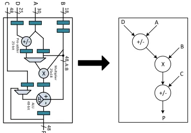
Fig. 4: Dataflow through the DSP48E1 primitive.
using a directive in the Tcl script. However, for Pipe, we let the schedule determine the number of pipeline stages as this reflects what an expert designer might do, and adding more stages might increase area for the purposes of comparison.
Another important factor is operand wordlengths. The input and output ports of the DSP block have different wordlengths. When the output of a DSP block is passed to anothers input, it must be either truncated, or the latter operations should be made wider. We choose to truncate and try to minimize the error using Gappa (discussed in more detail in Section V). This is equivalent to a multistage fixed point implementation though we can optimize for known and fixed inputs. Primary inputs that are narrower than the input ports of the DSP block are sign extended. To ensure that comparisons between all implementation techniques are fair, we manually handle
intermediate wordlengths in Comb, Pipe, and HLS to match
those determined for Inst for all operations. This is necessary because other techniques may implement wider operations in intermediate stages, thus skewing resource usage and accuracy making implementations incomparable. Note that in the case where the designer does require wider intermediate opera-tions, the tool can be modified to instantiate optimized multi-DSP-block operators thereby still guaranteeing performance.
Finally, since Combrequires the register balancing synthesis
feature to be enabled, we do so for all methods.
IV. SEGMENTINGDSP BLOCKS
In order to map as many nodes of the input dataflow graph to DSP blocks, it must first be segmented into sub-graphs, each of which matches a DSP block template as defined in Section III. The flow graph for a DSP48E1 primitive comprises three nodes, as shown in Fig. 4.
We explore two approaches to this segmentation problem. The first is a greedy algorithm, and the second applies a more global heuristic optimisation.
A. Greedy Segmentation
DSP block template since the DSP48E1 primitive is designed in such a way that intermediate outputs cannot be accessed externally without bypassing later sub-blocks. If the node has a single child, they are combined into a sub-graph, and the same process is repeated to add a third node to the sub-graph if possible. Sub-graph merging is also terminated if a node is a primary output of the top level graph.
Each time a sub-graph of one, two, or three nodes is extracted, it is matched against the template database and if a match is found, those nodes are marked as checked and not considered in subsequent iterations. If only a partial match is found, only those matched nodes are marked as checked. The process is repeated until all nodes are checked. Sub-graphs combining two add/sub nodes with no multiply nodes are reseparated with the root node implemented in LUTs, and the child node left for remerging with other nodes in further iterations. The output of this process is a graph consisting of DSP block templates (each with an associated latency) and some adder nodes to be implemented in logic.
The time complexity of the greedy segmentation algorithm is directly proportional to n, wherenis the number of nodes in graph.
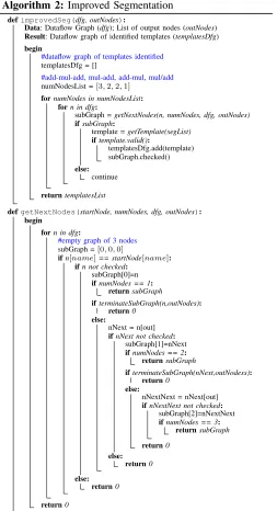
B. Improved Segmentation
The greedy algorithm discussed above can result in sub-optimal segmentation as it only considers local information starting from the inputs. We try an improved algorithm (de-tailed in Algorithm 2) that instead first finds possible sub-graphs which can be mapped to a DSP block template utilising all three sub-blocks, then subsequently finds the sub-graphs with two nodes, and then remaining single nodes.
The segmentation process is broken into four iterations. In the first iteration, only valid sub-graphs of three nodes are matched to the template database, as discussed in Section IV-A, and if a full match is found, these nodes are marked as checked. If only a partial match is found, all nodes are reseparated. In the second and third iterations, the same process is applied to all remaining unchecked nodes for sub-graphs of two nodes. There are two types of two-node templates: those that include the preadder and multiply sub-blocks, and those with the multiply and ALU sub-blocks. Since the ALU wordlength is wider than the preadder, we consider sub-graphs of the latter type in this second iteration. This also has the benefit of allowing a 1-cycle reduced latency through the DSP block, resulting a shorter overall pipeline depth, and hence reduced resource usage. In the third iteration two-node sub-graphs using the preadder are matched. Matched sub-graph nodes are then marked as checked. In the fourth iteration remaining uncovered nodes are considered individually and mapped to DSP blocks for multiply operations, or LUTs for additions/subtractions.
The time complexity of the improved segmentation algo-rithm is up to four times higher than for the greedy algoalgo-rithm, since four passes must be completed on the graph.
V. ERRORMINIMISATION
As discussed in Section I, the DSP block input and output ports have a range of widths. This results in a number of
Algorithm 1: Greedy Segmentation
defgreedySeg(dfg, outNodes):
Data: Dataflow Graph (dfg); List of output nodes (outNodes) Result: Dataflow graph of identified templates (templatesDfg)
begin
#dataflow graph of templates identified templatesDfg = []
#for each nodenin dfg forn in dfg:
#empty graph of 3 nodes subGraph =[0,0,0]
ifn not checked: subGraph[0]=n
ifterminateSubGraph(n, outNodes): template =getTemplate(subGraph)
else:
nNext = n[out] ifnNext not checked:
subGraph[1]=nNext
ifterminateSubGraph(nNext, outNodes): template =getTemplate(subGraph)
else:
nNextNext = nNext[out] ifnNextNext not checked:
subGraph[2]=nNextNext
template =getTemplate(subGraph)
else:
template =getTemplate(subGraph)
iftemplate:
templatesDfg.add(template)
#mark nodes of subGraph assigned to template checked subGraph.checked()
else: continue
returntemplatesDfg
defterminateSubGraph(n, outNodes): #if the node has been assigned to a template ifn is checked:
returnTrue
#if output going to multiple nodes iflen(n[out])>1:
returnTrue
#if output is primary output ifn[out]in outNodes:
returnTrue
returnFalse
possible ways to assign inputs to each DSP block, and the need for truncation when wider outputs are fed to narrower inputs in subsequent stages. Since the inputs are in fixed-point representation, we truncate intermediate signals when necessary while ensuring that the integer part is preserved; only the least significant fractional bits are trimmed. This is equivalent to a multistage fixed-point implementation, though we can optimize for known and fixed inputs.
There are two straightforward ways to reduce error when mapping to DSP blocks. The first is to ensure that we consider the width of operands when assigning them to inputs. Wider inputs should be bound to the wider inputs of the DSP block, especially when dealing with the25×18-bit multiplier. Second, when mapping a two-node sub-graph to a DSP block template, those that use the ALU sub-block are preferred to those using the preadder since that offers a wider 48-bit adder/subtractor, compared to the 25 bits of the preadder.
Algorithm 2: Improved Segmentation
defimprovedSeg(dfg, outNodes):
Data: Dataflow Graph (dfg); List of output nodes (outNodes) Result: Dataflow graph of identified templates (templatesDfg)
begin
#dataflow graph of templates identified templatesDfg = []
#add-mul-add, mul-add, add-mul, mul/add numNodesList =[3,2,2,1]
fornumNodes in numNodesList: forn in dfg:
subGraph =getNextNodes(n, numNodes, dfg, outNodes)
ifsubGraph:
template =getTemplate(segList)
iftemplate.valid():
templatesDfg.add(template) subGraph.checked()
else: continue
returntemplatesList
defgetNextNodes(startNode, numNodes, dfg, outNodes): begin
forn in dfg:
#empty graph of 3 nodes subGraph =[0,0,0]
ifn[name]== startNode[name]: ifn not checked:
subGraph[0]=n ifnumNodes == 1:
returnsubGraph
ifterminateSubGraph(n,outNodes): return0
else:
nNext = n[out] ifnNext not checked:
subGraph[1]=nNext ifnumNodes == 2:
returnsubGraph
ifterminateSubGraph(nNext,outNodess): return0
else:
nNextNext = nNext[out] ifnNextNext not checked:
subGraph[2]=nNextNext ifnumNodes == 3:
returnsubGraph
return0
else: return0
else: return0
return0
one DSP block is used as the input to another. Consider the
output of a DSP block performing a 25×18 bit multiplication
connected to the 25-bit preadder of a subsequent DSP block, a naive truncation of 18 bits could introduce significant error. However, analyzing the range of the multiplier operands we may find that the result precision does not in fact exceed 25 bits, and hence truncation can be done without introducing error.
Gappa [2] allows us to determine realistic, tight bounds for output ranges at individual nodes based on a provided input range, to avoid over-optimistic implementation while minimizing error in our mapping. Error minimization using
xMul4 = fixed<-15,ne>(4) * fixed<-15,ne>(x); node1 = fixed<-15,ne>(xMul4) * fixed<-15,ne>(x); node2 = fixed<-15,ne>(node1) - fixed<-15,ne>(0.625); node3 = fixed<-15,ne>(node2) * fixed<-15,ne>(node1); node4 = fixed<-15,ne>(node3) + fixed<-15,ne>(0.625); node5 = fixed<-15,ne>(node4) * fixed<-15,ne>(x);
{
(x in [0,1]) -> (
xMul4 in ? /\ node1 in ? /\ node2 in ? /\ node3 in ? /\ node4 in ? /\ node5 in ? )
[image:7.612.52.305.58.524.2]}
Fig. 5: Example Gappa script for expression x(4x2(4x2
−
0.625) + 0.625).
Gappa is done in two steps.
Step 1: From the dataflow graph of the input expression, ideal wordlengths for all intermediate outputs are determined using Gappa, based on the provided input range and precision. A Gappa script is generated and executed; an example is shown in Fig. 5.
This script has been generated for inputxbetween 0 and 1,
with a precision of 15 bits. Numbers are rounded to nearest with tie breaking to even mantissas. Execution of this script gives the range of all six intermediate outputs, from which the wordlengths of intermediate outputs are calculated ignoring the wordlength constraints of the DSP blocks, resulting in ideal wordlengths for an error-free implementation.
Step 2: The segmented graph’s intermediate outputs are bound to template ports based on signal width. Using this initial binding and the ideal wordlengths calculated in the pre-vious step, an iterative process follows to identify intermediate outputs not satisfying the ideal wordlength and try to minimize error.
The segmented graph is reformed in terms of the templates used (i.e., sub-graphs are represented as nodes), and all nodes are initially marked as unchecked. In each iteration, the tem-plate graph is traversed from the inputs. For each temtem-plate, all nodes are checked for error and if they satisfy the ideal wordlength, the template is marked as checked for all further iterations. If any node does not meet the required wordlength, it is marked as an error node. If the error node is an add/sub node, it is moved out of the DSP template, and is mapped to an LUT-based adder/subtractor template of width matching the ideal wordlength and then marked as checked. The remaining unchecked nodes are then segmented again (resegmentation) for further iterations. As we are using single DSP block templates, if the error node is a multiply node, inputs to the node are truncated to t the wordlength of DSP block port it is bound to.
inputs = <list of inputs separated by comma (,)>
input_ranges = <list of input ranges in {min,max} format, separated by (;)>
precision = <precision> <instruction1>
<instruction2> ...
<instruction(M-1)> <instructionM>
test_inputs [optional]
<input1> = <list of test inputs separated by comma> <input2> = <list of test inputs separated by comma> ...
<inputN> = <list of test inputs separated by comma> ---N: No of inputs; M: No of instructions
Fig. 7: Input expression file format.
Gappa scripts are generated, using the updated wordlengths of the checked nodes. This iterative process is terminated once all nodes have been checked for error. Using Gappa in this manner allows us to ensure that truncations take into account range properties to minimize error significantly.
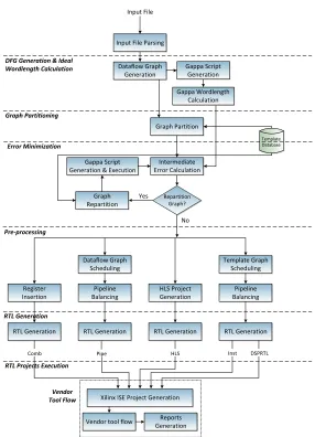
VI. AUTOMATEDMAPPINGTOOL
Bringing together the techniques discussed thus far, we have developed a fully automated mapping tool. It takes an add-multiply dataflow graph as input, and prepares synthesisable RTL implementations for all the mapping methods described in Section III, using either of the segmentation algorithms discussed in Section IV, with integration of Gappa for error minimization, as discussed in Section V. A flow diagram of the tool is shown in the Fig. 6.
A. Input File Parsing
The front-end accepts a text file listing the inputs of an expression with their ranges and precision. The expression is written as a series of two-operand operations. Fixed power-of-2 multiplications can be combined with other operators and are implemented using shifts, saving multipliers, e.g., 16x5
−
20x3+ 5x
⇒ x(4x×x(4x×x−5) + 5). For the purposes
of functional verification, the input file can also contain a set of test vectors. If these are provided, the tool also generates testbenches for all generated implementations. The format of the input file is shown in Fig. 7.
B. DFG Extraction and Ideal Wordlength Calculation
A dataflow graph is generated from the input file with each instruction represented as a node in the graph. The tool then generates a Gappa script to determine the range and ideal wordlengths of all intermediate and primary outputs based on the input precision and ranges provided in the input file. Each node is then tagged with its input and output ranges.
C. Graph Partitioning
The graph generated in the previous stage is then partitioned into sub-graphs using either of the methods discussed in Section IV. Each of these sub-graphs is either mapped to one of the DSP templates in the template database or an LUT-based adder. The sub-graphs input and output edges are then mapped to appropriate ports of DSP48E1 primitives. This transforms the input dataflow graph into a template graph, in which each node is a DSP block template.
D. Error Minimization
After calculating ideal wordlengths for the dataflow graph and initial partitioning, Gappa is used to iteratively minimise errors due to truncation and port assignment, as discussed in Section V.
E. Pre-processing
The tool now has a graph of multiplier and adder nodes with higher level information about mapping to DSP block templates with some nodes optionally mapped to logic. Some preprocessing is then necessary to allow generation of the various implementations.
1) Comb: As discussed in Section III, pipeline registers
are added at the output node(s) of the graph to facilitate retiming during synthesis.
2) Pipe: The graph is scheduled (both ASAP and ALAP
schedules are generated). Pipeline registers are added between dependent nodes.
3) Pipeline Balancing: It ensures dataflows through the
graph are correctly aligned. Nodes of the flow graph are assigned a level according to the schedule. The level of each node input is compared with the level of its source registers, and if the difference is greater than 1, balancing registers are added to correctly align the datapaths.
4) HLS: The input expression is converted to C++ with
each node of the flow graph implemented as an in-struction. If unit tests are given in the input file, a C++ testbench is also generated. Vivado HLS directives are used to set the pipeline latency, which is set equal to the latency ofInst. Other files required for the Vivado HLS project are also generated.
5) Inst, DSPRTL: After generating the template graph in
Graph Partitioning, the pipeline stages of the graph are
balanced to correctly align data flow, as forPipe.
F. RTL Generation
The Verilog code implementing the datapaths for all tech-niques and their testbenches are generated. For all techtech-niques, the wordlengths of the inputs and outputs of each node are explicitly set to the same as those of Inst for fair comparison.
ForComb, RTL implementing each node as combinational
Dataflow Graph Generation
Input File
Dataflow Graph Scheduling
Template Graph Scheduling Pipeline
Balancing
HLS Project Generation
Pipeline Balancing
RTL Generation RTL Generation RTL Generation RTL Generation
Xilinx ISE Project Generation
Comb HLS Inst DSPRTL
Vendor tool flow Reports Generation Vendor
Tool Flow Register Insertion
Pipe
Pre-processing
Input File Parsing
Graph Partition
Intermediate Error Calculation
Repartition Graph?
Yes
No
Template Database
Gappa Script Generation Gappa Wordlength
Calculation
Graph Repartition Gappa Script Generation & Execution Graph Partitioning
DFG Generation & Ideal Wordlength Calculation
Error Minimization
RTL Generation
[image:9.612.167.453.46.442.2]RTL Projects Execution
Fig. 6: Tool flow for exploring DSP block mapping.
For Pipe, all node operations and registers scheduled in a
particular schedule time are implemented as a pipeline stage,
in one Verilogalwaysblock.
For HLS, we run the Vivado HLS project generated in the
previous stage, which translates the high-level C++ implemen-tation of the input expression into synthesisable RTL. It also generates an equivalent RTL testbench from the C++ testbench.
For Inst, Verilog RTL for instantiations of the DSP block
templates along with the balancing registers are generated.
DSPRTL is an RTL equivalent ofInst, reflecting the internal
structure of the Inst implementation but using behavioural
Verilog blocks that for each DSP block template. Intermediate signals are first shifted then truncated depending on the desti-nation wordlength. If error minimisation is enabled, then the shift amount is dependent on this analysis, else, a basic range analysis is applied.
G. Vendor Tool Flow
The RTL files for all above methods are then synthesized through the implementation vendor tools. Since this can be time consuming, we have automated the process through a series of scripts. First, ISE Projects are generated for all tech-niques with specific device and timing constraints. Synthesis is then run, and the reports stored. Implementation stages are then run iteratively to determine the minimum achievable clock period. A default timing constraint is used first and if the design fails, the constraint is relaxed until the post place and route implementation satisfies it. Resource requirements are also extracted from the post place and route reports for analysis.
VII. EXPERIMENTS
TABLE I: Number of I/O ports and operations.
Benchmark Inputs Outputs Add/Subs Muls
ARF 26 2 12 16
Chebyshev 1 1 2 3
EWF 21 5 26 8
FIR2 17 1 15 8
Horner Bezier 12 4 6 8
Mibench2 3 1 8 6
Motion Vector 25 4 12 12
Poly1 2 1 5 4
Poly2 2 1 3 5
Poly3 6 1 4 6
Poly4 5 1 3 3
Poly5 3 1 13 11
Poly6 3 1 19 23
Poly7 3 1 18 17
Poly8 3 1 16 15
Quad Spline 7 1 4 13
SG Filter 2 1 6 6
Smooth Triangle 29 14 20 17
implemented a number of benchmark multiply-add ow graphs. These include the Chebyshev polynomial, Mibench2 lter, quadratic spline, and SavitzkyGolay lter from [21]; the ARF, EWF, FIR2, Horner Bzier, motion vector, and smooth triangle extracted from MediaBench [22]; and eight polynomials of varied complexity from the Polynomial Test Suite [23]. We prepared input files for all 18 of these expressions for pro-cessing through our tool. Table I shows the number of inputs and outputs, and number of each type of operation (add/sub, multiplier) for all benchmarks.
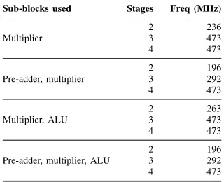
To better understand the limits of DSP block performance, we explored the maximum frequency achievable for different template configurations, as shown in Table II. We can see that a three-cycle pipeline offers maximum performance when the pre-adder is not used, and a four-cycle pipeline is required to achieve the same frequency if the pre-adder is used. We map only to template configurations that achieve this maximum frequency of 473 MHz to maximise overall circuit throughput.
TABLE II: Maximum frequency of a DSP48E1 for different blocks used, with different number of pipeline stages.
Sub-blocks used Stages Freq (MHz)
2 236
Multiplier 3 473
4 473
2 196
Pre-adder, multiplier 3 292
4 473
2 263
Multiplier, ALU 3 473
4 473
2 196
Pre-adder, multiplier, ALU 3 292
[image:10.612.82.269.85.244.2]4 473
TABLE III: Runtime of the segmentation algorithms (ms).
Benchmark Greedy Segmentation Improved Segmentation w/o Gappa w/ Gappa w/o Gappa w/ Gappa
ARF 12.8 21.5 13.0 21.5
Chebyshev 36.2 48.6 37.9 49.1
EWF 67.4 81.3 70.7 82.5
FIR2 22.2 32.4 21.7 31.5
Horner Bezier 20.8 29.6 21.7 30.0
Mibenc2 18.3 26.6 17.8 25.9
Motion Vector 26.3 36.3 27.8 37.2
Poly1 18.4 25.8 18.8 25.8
Poly2 75.7 94.4 79.1 95.3
Poly3 308.3 339.4 363.2 377.5
Poly4 231.7 274.2 244.9 276.9
Poly5 108.3 144.2 124.6 156.3
Poly6 251.9 326.8 266.7 328.3
Poly7 358.1 505.7 378.3 509.7
Poly8 126.0 213.9 124.9 217.9
Quad Spline 34.4 68.1 32.8 68.8
SG Filter 45.5 92.7 43.8 94.1
Smooth Triangle 600.1 884.1 606.0 854.4
Geometric Mean 67.3 96.3 69.6 97.6
A. Tool Runtime
The proposed tool is run on an Intel Xeon E5-2695 running at 2.4 GHz with 16GB of RAM. The times taken to generate synthesisable RTL from the high-level description for both segmentation methods, with and without error minimisation, averaged over 100 executions, are shown in Table III. These runtimes include the time taken by Gappa to determine in-termediate signal wordlengths for inputs in range [0,1] with 15-bit precision. The runtimes are entirely tolerable as part of a larger design flow. Smooth Triangle, which results in the highest number of templates after segmentation, takes under a second. On average, a benchmark can generate RTL in less than 70 ms without using Gappa and under 100 ms with error minimisation.
I/O wordlength does not affect the runtime if error min-imisation is not applied, as intermediate outputs are simply truncated. Error minimisation means the segmentation process is repeated to minimise error and runtime does increase with I/O wordlength, although not significantly. The maximum runtime for a benchmark with an input range[0,15]and 31-bit precision is approximately 1.2 seconds.
We also measured the runtime for processing a synthet-ically generated dataflow graph with 36 inputs, 9 outputs, and 225 nodes, which was approximately 3.85 or 4 seconds (greedy/improved respectively) to RTL generation. This circuit would consume a significant proportion of the DSP blocks on a moderate sized FPGA.
B. Resource Usage and Frequency
[image:10.612.95.255.559.689.2]sub-block usage but overall DSP block usage is the same for both methods since the number of multipliers generally determines this.
To compare area resource usage between different tech-niques, we compare the area usage in equivalent LUTs,
LUTeqv =nLUT +nDSP ×(196), where 196 is the ratio
of LUTs to DSP blocks on the target device used, a proxy for overall area consumption.
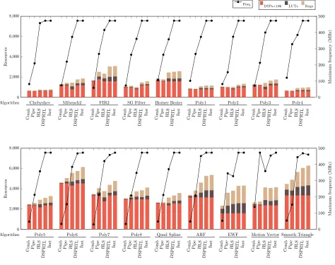
It is clear that the performance ofCombis the worst among
all techniques. The vendor tools are not able to absorb registers into a very deep combinational datapath. The maximum
fre-quency for Instis generally much improved (3.4–15.6×) over
Comb, at a cost of increasedLUTeqv usage, up to 1.3×.
Al-though the throughput of PipeandHLSimprove significantly,
they do not approach the maximum frequency supported by the DSP blocks (450–500 MHz) for most benchmarks. For
Pipe, we implemented both ASAP and ALAP schedules, and
chose the one with higher throughput. The performance of
HLS is generally better than Pipe. For the ARF and Smooth
Triangle benchmarks, which have regular repetitive structures,
HLS is able to achieve a frequency close to that achieved
by Inst. However, for FIR2 and Motion Vector, which also
have a regular structure, HLS falls short. The Chebyshev
dataflow graph is very narrow, and HLS is able to implement
it efficiently. For Motion Vector and EWF, Pipe achieves
a higher frequency than HLS. For Motion Vector, the Pipe
graph schedule and structure fit well with the DSP blocks, and also allows the mapping tool to take advantage of the internal cascade connection from PCOUT (DSP1) to PCIN (DSP2), reducing routing delay significantly. For EWF, the schedule of the dataflow graph feeds forward with no parallel delay paths. As a result, all the sub-blocks are used in 4 DSP blocks while the other 4 use 2 sub-blocks, leading to
high throughput. On the contrary, HLSuses the DSP blocks
mostly for multiplications (7 out of 8) with extra nodes in
logic. For complex graphs, both Pipe and HLS are unable
to come close the frequency achievable using our proposed
techniques. The maximum frequency for Instis up to 3×and
1.4×better thanPipeandHLSrespectively. We expect Vivado
HLS, being the most architecture aware high-level synthesis tool for Xilinx devices, to be the most competitive HLS tool for such mappings.
We analysed the DSP block configurations used in Pipe
and HLS implementations. For Pipe, the tools utilise
sub-blocks well but do not enable all pipeline stages due to the fixed schedule and only one register stage between dependent nodes. This significantly affects throughput, as previously
demonstrated in Table II. For HLS, we have observed that
sub-blocks are not used very often. Across all 169 DSP48E1
primitives used by HLS across all benchmarks, none use all
three sub-blocks, while forInst, 46 such instances exist. Since we set the pipeline latency forHLSto equal that ofInst, it has sufficient slack to achieve similar performance, and this also explains some of its advantage over Pipe.
We show sub-block usage across all benchmarks in Fig. 9. ForCombandPipe, over half the DSP blocks are used only for multiplication, and this is even higher forHLS. The proposed
DSPRTL and Inst methods make more use of the sub-blocks
Comb Pipe HLS DSPRTL Inst 0
20 40 60 80 100
[image:11.612.363.524.56.191.2]PreAdd-Mul-ALU Mul-ALU PreAdd-Mul Mul
Fig. 9: DSP48E1 primitive sub-block utilisation.
0.8 1 1.2 1.4 1.6 1.8 2 200
300 400 500
Regs+LUTs
Max
F
requency
2 stage 3 stage Inst HLS
Fig. 10: Frequency-resource trade-off.
including around 20% of instances using all three sub-blocks. Overall, we see that the throughput achievable by existing methods is significantly less than what we are able to achieve
through our proposed Inst and DSPRTL approaches, though
the proposed methods suffer from higher resource usage due to heavily pipelined structures. The proposed methods use DSP block templates with either 3 or 4 stages (depending on the sub-blocks used). This pipelining within the DSP block is “free” since those registers are not implemented in the fabric, however, extra registers are then required to balance
other paths through the graph. Pipeline depths for the Pipe
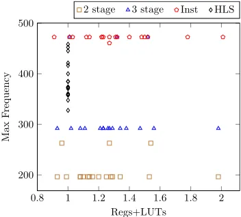
and other approaches are shown in Table IV. Fig. 10 shows an area/throughput trade-off using DSP block templates of different pipeline depths. Resource usage (#Regs+ #LU T s)
is normalized against HLS for all benchmarks. Out of 18
benchmarks, only 6 achieve over 400 MHz using HLS, while
Inst implementations can run at over 450 MHz for all
bench-marks. This higher frequency comes at the expense of re-sources required for balancing registers. Benchmarks with no pre-adder templates can achieve high throughput using 2 and 3 stage DSP block templates (as evident from Table II).
[image:11.612.358.534.237.396.2]max-Com b Pip e HLS DSPR TL Inst Com b Pip e HLS DSPR TL Inst Com b Pip e HLS DSPR TL Inst Com b Pip e HLS DSPR TL Inst Com b Pip e HLS DSPR TL Inst Com b Pip e HLS DSPR TL Inst Com b Pip e HLS DSPR TL Inst Com b Pip e HLS DSPR TL Inst Com b Pip e HLS DSPR TL Inst 0
2,000 4,000 6,000 8,000
Chebyshev Mibench2 FIR2 SG Filter Horner Bezier Poly1 Poly2 Poly3 Poly4
Algorithm
Resources
DSPs×196 LUTs Regs
0 100 200 300 400 500 Maxim um frequency (MHz) Freq Com b Pip e HLS DSPR TL Inst Com b Pip e HLS DSPR TL Inst Com b Pip e HLS DSPR TL Inst Com b Pip e HLS DSPR TL Inst Com b Pip e HLS DSPR TL Inst Com b Pip e HLS DSPR TL Inst Com b Pip e HLS DSPR TL Inst Com b Pip e HLS DSPR TL Inst Com b Pip e HLS DSPR TL Inst 0
2,000 4,000 6,000 8,000
Poly5 Poly6 Poly7 Poly8 Quad Spline ARF EWF Motion Vector Smooth Triangle
[image:12.612.78.552.53.428.2]Algorithm Resources 0 100 200 300 400 500 Maxim um frequency (MHz)
Fig. 8: Resource usage and maximum frequency.
TABLE IV: Pipeline depth for Pipe and other approaches
(Comb/HLS/Inst DSPRTL).
Benchmark Pipe Others Benchmark Pipe Others
ARF 9 26 Poly5 10 24
Chebyshev 6 14 Poly6 12 31
EWF 15 28 Poly7 13 34
FIR2 10 27 Poly8 12 31
Mibenc2 7 16 Horner Bezier 5 12
Poly1 5 13 Motion Vector 5 11
Poly2 5 13 Quad Spline 7 22
Poly3 6 15 SG Filter 8 14
Poly4 5 12 Smooth Triangle 7 21
imum frequency but the improved algorithm marginally
im-proves LUTeqv usage by 1–3% in some cases. Combining
frequency results across all benchmarks, the geometric mean
in the frequency improvement ofInstis 7.4×over Comb, 2×
over Pipe, and 1.2×over HLS. These gains are at the cost of
1.1–1.23×LUTeqv usage, compared to other methods.
A key positive finding of this study is that maximum DSP block frequency can be achieved without architecture-specific instantiation of the DSP48E1 primitive. Explicit instantiation of primitives is not desirable as it leads to complex code
and hinders portability to other architectures. With DSPRTL,
we instead replace those direct instantiations with behavioural Verilog code that exactly matches the required template, in-cluding pipeline configuration. We can see that this offers almost the same performance asInstbut with code that remains portable. The tools can correctly map these general templates to DSP blocks, including internal pipeline stages. Just offering sufficient pipeline stages (as we do forHLS) does not guarantee maximum throughput. It is essential to take into account the structure of the DSP blocks when translating the dataflow graph into Verilog for implementation.
[image:12.612.73.281.530.621.2]TABLE V: RMS error reduction due to Gappa.
Without Gappa With Gappa Improvement (×)
range:[0,1] 0.0020 0.0013 1.54
precision: 15
range:[0,15] 0.0922 0.0013 70.92
precision: 15
range:[0,1] 0.0021 0.0009 2.33
precision: 31
range:[0,15] 0.0919 0.0008 114.88
precision: 31
register stage after each extracted DSP block template for this to work, likely because the tools could only correctly map to DSP blocks with a margin of one cycle between them to break the possible long routing paths between subsequent DSP blocks and reduce routing delays. Although there are cascade wires that allow DSP blocks in a column to be connected without going through the routing fabric, these connect the output of a DSP block to only the ALU input of the subsequent block, limiting their use in general mapping where the output of a DSP block may need to be connected to any input of a subsequent block. This tweak significantly improved the
performance of DSPRTLfrom a mean frequency of 383 MHz
to 470 MHz, close the 471 MHz of Inst.
C. Error Minimisation
As discussed in Section V, we have used Gappa to iterate and re-segment the graph to minimise error. To analyse the impact on error by incorporating Gappa, we have compared the error results with and without the Gappa analysis, over 1000 randomly generated test inputs, distributed uniformly between the range of inputs.
Error is calculated as follows:
error = 1000
P
i=1
|outi−idealouti| idealouti
1000 (1)
All 18 benchmarks together produce 42 outputs (Table I). We explore the effect of the Gappa optimisation across all the benchmark outputs using root mean square (RMS) error:
rmsError= v u u u t
42 P
i=1
errori2
42 (2)
To analyse how error varies with the increase in
[image:13.612.346.545.93.153.2]wordlengths, we run these error experiments on a set of four inputs ranges and precisions. With a precision of 15 bits, we calculate error for inputs ranges of [0,1] and[0,15]; and we repeat this with a precision of 31 bits. The results are shown in Table V for improved segmentation. We can see that for smaller inputs ranges, error is not very significant even without using the Gappa optimisation. This is because the integer parts of intermediate outputs do not exceed DSP block input port ranges for most intermediate outputs, and for those where the
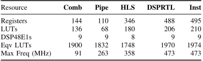
TABLE VI: Resource usage and frequency for color saturation correction case study.
Resource Comb Pipe HLS DSPRTL Inst
Registers 144 110 346 488 495
LUTs 136 68 180 206 210
DSP48E1s 9 9 8 9 9
Eqv LUTs 1900 1832 1748 1970 1974
Max Freq (MHz) 91 263 358 473 473
range is exceeded, only fractional bits are trimmed, adding a small amount of error.
However, with the larger input range of [0,15], we see
a significant increase in error, from approximately 0.2% to more than 9%. Without the Gappa optimisation, intermedi-ate wordlengths are calculintermedi-ated by considering the maximum possible output ranges, resulting in wider intermediate outputs and more truncation in the fractional parts, and in some cases, truncation in lower significant bits of integer parts, resulting in significant error. We also found that the preference of the ALU over the pre-adder for 2-node templates had negligible impact on overall error. The Gappa optimisation allows our tool to determine tighter bounds for intermediate outputs, resulting in the ability to trim unnecessary integer MSBs without introducing error. Overall, adding Gappa optimisation allows much larger input ranges to be mapped with comparable error.
D. Case Study
We also designed an end-to-end case study implementation of “Colour Saturation Correction” from high-level descrip-tion to implementadescrip-tion, and testing on the Xilinx ML605 development board. The algorithm takes RGB values, with a percentage saturation value representing the amount of colour to be added back to the luminance, outputting the saturation-corrected image.
We use improved segmentation with error minimisation using Gappa. The resulting segmented dataflow graph is shown in Fig. 11. We validated the generated RTL on-board, using the open-source DyRACT framework [24], which allows us to test the design with multiple images easily, interfacing over PCIe.
The resource usage and maximum frequency for all methods
are shown in Table VI.Instachieves a frequency improvement
of 5.2× over Comb, 1.8× over Pipe, and 1.3× over HLS.
These gains are at the cost of a 4–13% increase in equivalent LUT usage. We verified the correctness of the implementations against a Python model of the same algorithm, with negligible error recorded.
VIII. CONCLUSIONS
redIn
n1mul
n8sub 70
redIn
n2mul
n9add n11add 30 greenIn
n3mul
n7add 59
greenIn
n4mul
n12sub 41 blueIn
n5mul
n13add 11
blueIn
n6mul
n10sub 89
n14mul n16mul n15mul
n17add n18add n19add
sat sat sat
[image:14.612.77.279.52.186.2]redOut greenOut blueOut
Fig. 11: Segmented dataflow graph for the Color Saturation Correction case study.
DSP blocks, exploiting the various supported configurations and enabling pipeline stages as needed to achieve maximum throughput, including balancing of parallel flows. Error anal-ysis using Gappa allows truncation to be applied intelligently thereby minimising error in the final output. We modify our tool to produce a number of other typical mappings and present detailed results comparing our approach. We show consistently better throughput than all other methods, including a mean
1.2× improvement over Vivado HLS, at the cost of a 1.1–
1.23×increase in LUT area.
We are working on an extension of this paper to allow resource-constrained implementations by exploiting the dy-namic programmability of the DSP block. We also plan to release our tool for use by others interested in these investi-gations. Integration within a functional HLS flow would also allow these results to be exploited in more complex designs.
REFERENCES
[1] Xilinx Inc.,UG479: 7 Series DSP48E1 Slice User Guide, 2013.
[2] F. de Dinechin, C. Q. Lauter, and G. Melquiond, “Assisted verification of elementary functions using Gappa,” in Proceedings of the ACM Symposium on Applied Computing, 2006, pp. 1318–1322.
[3] Z. Chun, Z. Yongjun, C. Xin, and G. Xiaoguang, “Research on tech-nology of color space conversion based on DSP48E,” inInternational Conference on Measuring Technology and Mechatronics Automation (ICMTMA), vol. 3, 2011, pp. 87–90.
[4] G. Conde and G. Donohoe, “Reconfigurable block floating point pro-cessing elements in Virtex platforms,” inProceedings of the Interna-tional Conference on Reconfigurable Computing and FPGAs (ReCon-Fig), 2011, pp. 509–512.
[5] F. Brosser, H. Y. Cheah, and S. A. Fahmy, “Iterative floating point computation using FPGA DSP blocks,” in Proceedings of the Inter-national Conference on Field Programmable Logic and Applications (FPL), 2013.
[6] R. Mehra and S. Devi, “FPGA implementation of high speed pulse shaping filter for SDR applications,” inRecent Trends in Networks and Communications. Springer Berlin Heidelberg, 2010.
[7] A. de la Piedra, A. Braeken, and A. Touhafi, “Leveraging the DSP48E1 block in lightweight cryptographic implementations,” inProceedings of the IEEE International Conference on e-Health Networking, Applica-tions & Services (HealthCom), 2013, pp. 238–242.
[8] S. Xu, S. A. Fahmy, and I. V. McLoughlin, “Square-rich fixed point polynomial evaluation on FPGAs,” inProceedings of the ACM/SIGDA International Symposium on Field-Programmable Gate Arrays (FPGA), 2014, pp. 99–108.
[9] H. Y. Cheah, F. Brosser, S. A. Fahmy, and D. L. Maskell, “The iDEA DSP block-based soft processor for FPGAs,” ACM Transactions on Reconfigurable Technology and Systems (TRETS), vol. 7, no. 3, pp. 19:1–19:23, Sep. 2014.
[10] “[Online] Impulse-C,” http://www.impulsec.com/. [11] “[Online] Bluespec,” http://www.bluespec.com/.
[12] A. Canis, J. Choi, M. Aldham, V. Zhang, A. Kammoona, J. H. Anderson, S. Brown, and T. Czajkowski, “LegUp: high-level synthesis for FPGA-based processor/accelerator systems,” inProceedings of the ACM/SIGDA International Symposium on Field Programmable Gate Arrays (FPGA), 2011, pp. 33–36.
[13] “[Online] Xilinx Autopilot,” http://www.xilinx.com/.
[14] F. De Dinechin and B. Pasca, “Designing custom arithmetic data paths with FloPoCo,”IEEE Design & Test of Computers, vol. 28, no. 4, pp. 18–27, 2011.
[15] J. Rose, J. Luu, C. W. Yu, O. Densmore, J. Goeders, A. Somerville, K. B. Kent, P. Jamieson, and J. Anderson, “The VTR project: archi-tecture and CAD for FPGAs from verilog to routing,” inProceedings of ACM/SIGDA International Symposium on Field Programmable Gate Arrays, 2012, pp. 77–86.
[16] P. Jamieson, K. B. Kent, F. Gharibian, and L. Shannon, “Odin II -an open-source Verilog HDL synthesis tool for CAD research,” in Proceedings of the IEEE Annual International Symposium on Field-Programmable Custom Computing Machines (FCCM), 2010, pp. 149– 156.
[17] A. Tisserand, “Automatic generation of low-power circuits for the evaluation of polynomials,” in Conference Record of the Asilomar Conference on Signals, Systems and Computers, Oct 2006, pp. 2053– 2057.
[18] ——, “Function approximation based on estimated arithmetic opera-tors,” in Conference Record of the Asilomar Conference on Signals, Systems and Computers, Nov 2009, pp. 1798–1802.
[19] M. D. Linderman, M. Ho, D. L. Dill, T. H. Meng, and G. P. Nolan, “To-wards program optimization through automated analysis of numerical precision,” inProceedings of the IEEE/ACM International Symposium on Code Generation and Optimization, 2010, pp. 230–237.
[20] H. Martorell and N. Kapre, “FX-SCORE: A framework for fixed-point compilation of SPICE device models using Gappa++,” inProceedings of the IEEE International Symposium on Field-Programmable Custom Computing Machines (FCCM), April 2012, pp. 77–84.
[21] S. Gopalakrishnan, P. Kalla, M. B. Meredith, and F. Enescu, “Find-ing linear build“Find-ing-blocks for RTL synthesis of polynomial datapaths with fixed-size bit-vectors,” inProceedings of IEEE/ACM International Conference on Computer-Aided Design, Nov 2007, pp. 143–148. [22] C. Lee, M. Potkonjak, and W. Mangione-Smith, “MediaBench: a tool
for evaluating and synthesizing multimedia and communications sys-tems,” inProceedings of International Symposium on Microarchitecture, Dec 1997, pp. 330–335.
[23] “[Online] Polynomial Test Suite,” http://www-sop.inria.fr/saga/POL/. [24] K. Vipin and S. A. Fahmy, “DyRACT: A partial reconfiguration
Bajaj Ronakreceived his B.Tech. degree in Elec-tronics and Communication Engineering from the International Institute of Information Technology, Hyderabad (IIIT-H), India, in 2010. From 2010 to 2011, he worked as an intern at Xilinx Research Labs, India. Since 2011, he has been pursuing the Ph.D. degree with the School of Computer Engineer-ing at Nanyang Technological University, SEngineer-ingapore, working on architecture awareness in high-level syn-thesis.
Suhaib A. Fahmy (M’01, SM’13) received the
M.Eng. degree in Information Systems Engineering and the Ph.D. degree in Electrical and Electronic Engineering from Imperial College London, UK, in 2003 and 2007, respectively.
From 2007 to 2009, he was a Research Fellow at Trinity College Dublin, and a Visiting Research Engineer with Xilinx Research Labs, Dublin. Since 2009, he has been an Assistant Professor with the School of Computer Engineering at Nanyang Technological University, Singapore. His research interests include reconfigurable computing, high-level system design, and computational acceleration of complex algorithms.