University of Warwick institutional repository: http://go.warwick.ac.uk/wrap
A Thesis Submitted for the Degree of PhD at the University of Warwick
http://go.warwick.ac.uk/wrap/55482
This thesis is made available online and is protected by original copyright. Please scroll down to view the document itself.
Piotr Bart lomiej Dubla
B.Sc. (Hons)
A thesis submitted in partial fulfilment of the requirements for
the degree of
Doctor of Philosophy in Engineering
School of Engineering
Acknowledgements x
Declaration xi
List of Publications xii
Abstract xiii
1 Introduction 1
1.1 Physically-based Rendering . . . 1
1.2 Ray tracing . . . 3
1.3 Interactive Global Illumination . . . 4
1.4 Research Objectives . . . 8
1.5 Thesis Outline . . . 9
2 Background 11 2.1 Introduction to Rendering . . . 11
2.1.1 Radiometry . . . 11
2.1.2 Surface Interactions of Light . . . 12
2.1.3 Light Transport . . . 14
2.2 Primary Rendering Techniques . . . 16
2.2.1 Rasterisation . . . 16
2.2.2 Ray Tracing . . . 17
2.2.3 Radiosity . . . 18
2.3 Accelerating Rendering . . . 19
2.3.2.1 Rasterisation . . . 22
2.3.2.2 Ray tracing . . . 22
2.3.2.3 Perception . . . 23
2.3.3 Interleaved Sampling . . . 24
2.3.4 Dynamic Acceleration Structures . . . 25
2.3.5 Irradiance Caching . . . 27
2.4 Synchronisation . . . 30
2.4.1 Blocking . . . 30
2.4.2 Busy-waiting . . . 31
2.4.3 Non-blocking . . . 31
2.4.4 Atomic Primitives . . . 32
3 Interactive Global Illumination 33 3.1 Interactive Ray Tracing . . . 33
3.1.1 CPU Algorithms . . . 34
3.1.1.1 Systems . . . 34
3.1.1.2 Algorithmic enhancements . . . 36
3.1.2 GPU Algorithms . . . 37
3.1.2.1 Systems . . . 37
3.1.2.2 Acceleration Data Structures . . . 38
3.2 Interactive Global Illumination . . . 40
3.2.1 CPU Algorithms . . . 41
3.2.1.1 Systems . . . 41
3.2.1.2 Radiosity . . . 43
3.2.1.3 Sparse sampling . . . 44
3.2.2 GPU Algorithms . . . 48
3.2.2.1 Radiosity . . . 48
3.2.2.2 Instant Radiosity . . . 50
3.2.2.3 Image-based methods . . . 53
3.2.2.4 Photon Mapping . . . 54
3.3 Discussion . . . 57
3.4 Summary . . . 61
4 Impact of Selective Rendering on Interactive Ray Tracing 62 4.1 Introduction . . . 62
4.2 Experimental Framework . . . 63
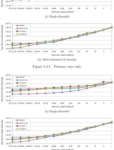
4.3 Experiment . . . 64
4.4 Results . . . 68
4.5 Discussion . . . 69
4.6 Summary . . . 70
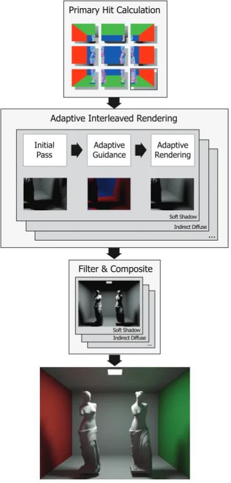
5 Adaptive Interleaved Sampling for Interactive Global Illumina-tion 71 5.1 Introduction . . . 71
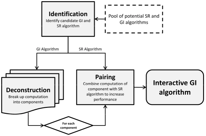
5.2 Framework . . . 72
5.2.1 Identification . . . 73
5.2.2 Deconstruction . . . 74
5.2.3 Pairing . . . 76
5.2.4 Implementation . . . 78
5.3 Adaptive Interleaved Sampling (AIS) . . . 80
5.3.1 Algorithm . . . 84
5.3.2 Indirect Diffuse Lighting . . . 85
5.3.3 Soft Shadows . . . 86
5.3.4 Single-scattering Participating Media . . . 88
5.4 Results . . . 90
5.4.1 Validation . . . 93
5.5 Summary . . . 97
6 Instant Caching for Interactive Global Illumination 99 6.1 Introduction . . . 99
6.2 Instant Caching . . . 100
6.3 Results . . . 108
6.3.1 Static images . . . 108
6.3.2 Animations . . . 111
6.3.3 Validation . . . 112
6.4 Summary . . . 114
7 Wait-Free Shared-Memory Irradiance Cache 116 7.1 Introduction . . . 116
7.2 Algorithms . . . 118
7.2.1 Lock-Based Irradiance Cache (LCK) . . . 118
7.2.2 Local-Write Irradiance Cache (LW) . . . 119
7.2.3 Wait-Free Irradiance Cache (WF) . . . 120
7.3 Results . . . 121
7.3.1 Still images . . . 123
7.3.2 Animations . . . 126
7.4 Summary . . . 129
8 Conclusions and Future Work 131 8.1 Conclusions . . . 131
8.2 Contributions . . . 133
8.3 Impact . . . 135
8.4 Limitations and Extensions . . . 136
8.5 Directions for Future Work . . . 138
8.6 Final Remarks . . . 139
References 141
A Adaptive Interleaved Sampling 170
1.2.1 The concept of ray tracing. . . 4
1.2.2 Examples of images rendered using path-tracing. . . 5
1.3.1 Explanation of interpolation via adaptive sampling. . . 7
2.1.1 BRDF examples. . . 13
2.3.1 Component-based Rendering. . . 21
2.3.2 Aleph map. . . 24
2.3.3 Interleaved sampling. . . 25
2.3.4 Samples in an irradiance cache. . . 28
3.1.1 Manta interactive ray tracer. . . 36
3.2.1 Razor. . . 43
3.2.2 Progressive radiosity. . . 44
3.2.3 Holodeck simulation. . . 45
3.2.4 Render Cache. . . 46
3.2.5 Corrective splatting. . . 47
3.2.6 Antiradiance. . . 50
3.2.7 Real-time Indirect Illumination with Clustered Visibility. . . 52
3.2.8 Screen-space directional occlusion. . . 53
3.2.9 Photon mapping on the GPU. . . 55
3.2.10Micro-Rendering. . . 57
4.2.1 Explanation how stride changes. . . 63
4.2.2 The four scenes used. . . 65
4.3.3 Secondary rays only. . . 67
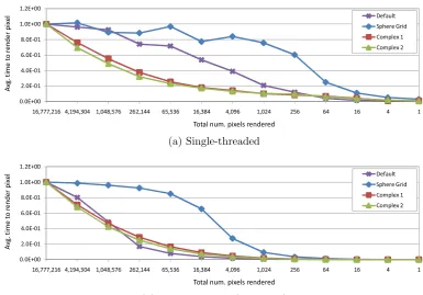
4.3.4 Normalised speed-up compared to 4096×4096. . . 67
5.2.1 Framework flowchart . . . 73
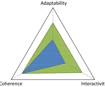
5.2.2 Explanation of framework goals. . . 76
5.2.3 AIS pipeline. . . 81
5.3.1 The three steps used in adaptive interleaved sampling. . . 83
5.3.2ID adaptive guidance. . . 85
5.3.3SS adaptive guidance. . . 87
5.3.4PM adaptive guidance. . . 88
5.3.5 The scenes used for obtaining AIS results. . . 92
5.3.6 AIS participating media scenes. . . 93
5.4.1 Office scene (including the PM version). . . 95
6.2.1 Irradiance cache vs. instant cache. . . 103
6.2.2 The five cases. . . 104
6.2.3 The scenes used for all experiments. . . 109
6.3.1 HDR-VDP comparisons for the Office scene. . . 115
7.2.1 The five scenes utilised in the experiments. . . 123
7.3.1 Still Images: Results for all scenes. . . 128
7.3.2 Animation results for Cornell Box. . . 128
7.3.3 Animation results for Conference Room. . . 129
A.1 Indirect diffuse (ID). . . 171
A.2 Guidance ID. . . 172
A.3 Soft shadows (SS). . . 173
A.4 Guidance SS. . . 174
A.5 Participating Media (PM). . . 175
A.6 Guidance PM. . . 176
A.7 Instant Global Illumination (IGI). . . 177
A.8 AIS with maximum samples (A-MAX). . . 179
A.11 VDP results for A-MAX vs. PT . . . 185
A.12 VDP results for IGI vs. PT . . . 186
4.1 Scene details . . . 64
5.1 Eleven scenes rendered with different components. . . 96
5.2 Speedup for the 11 scenes. . . 96
5.3 Results for HDR-VDP calculations in %. . . 97
6.1 Results for rendering the first frame. . . 110
6.2 Results for the diffuse interreflections only. . . 110
6.3 Results for rendering the animations. . . 111
6.4 Rendering times averaged over 100 frames. . . 112
6.5 Results of the HDR-VDP comparison. . . 113
7.1 Results for all scenes. . . 125
Firstly I would like to thank my supervisors, Alan and Kurt. Alan, if it wasn’t for your laptop troubles at Afrigraph all those years ago and our chance meeting I would not be where I am now, and for that I will be forever grateful. You not only remembered me after all those years when I was ready to do a PhD but also went out of your way to ensure that I could join you in Bristol and become part of your group. Kurt, you’ve been both a great friend and a mentor, your extensive graphics knowledge and love of research pushed me to try new things and better my own knowledge as much as I could, this thesis would not be what it is without your guidance and patience. I am indebted to you both, and your constant support and motivation are reflected in this thesis and all my research. To the other members of the research group, our collaborations not only made for more varied and interesting research but your friendships balanced out these four years and all our arguments, discussions and outings made the PhD a fantastic experience I will never forget. Our time together formed friendships that span most of Europe and beyond so I’d like to say thank you to Tom, Vedad, Jass, Vibhor, Mike, Alena, Carlo, Elmedin, Alessandro, Francesco, Belma, Ela, Gabriela, Matt, Remi and Sandro and I wish you all the best in your future endeavours, whatever they may be.
I would like to thank my father who didn’t even blink an eye when I said I was leaving a comfortable and successful job to pursue a PhD and who happily bought me a one-ticket to England and told me to go chase my dreams. I also dedicate this PhD to both my mother and my grandfather, both of whom regret-tably passed away during the last four years and never got the chance to see me complete it.
Finally I would like say thank you to all the people I have missed or not mentioned, there was so many others who were part of the whole PhD process and helped me in numerous ways during the past four years. I am also thankful to the University of Bristol and University of Warwick for all the support as well as the EPSRC for funding my research via the UK-EPSRC grant EP/D069874/2.
The work in this thesis is original and no portion of work referred to here has been submitted in support of an application for another degree or qualification of this or any other university or institute of learning.
Signed: Date: November 2010
Piotr Dubla
The following have been published as a result of the work contained within this thesis.
Journal papers
• Dubla P., Debattista K., Chalmers A.: Adaptive Interleaved Sampling for Interactive High Fidelity Rendering. Computer Graphics Forum (Volume 28, Issue 8, December 2009). Eurographics Association.
• Debattista K., Dubla P., Banterle F., Santos L.P., Chalmers A.: Instant Caching for Interactive Global Illumination. Computer Graphics Forum (Volume 28, Issue 8, December 2009). Eurographics Association.
• Debattista K., Dubla P., Santos L.P., Chalmers A.: Wait-Free Shared-Memory Irradiance Cache. Computer Graphics and Applications (Preprint). IEEE.
Peer-reviewed Conference Papers
• Dubla P., Debattista K., Santos L.P., Chalmers A.: Wait-Free Shared-Memory Irradiance Cache. In the 10th Eurographics Symposium on Par-allel Graphics and Visualization (Munich, Germany, 2009) Eurographics Association.
• Dubla P., Chalmers A., Debattista K.: An Analysis of Cache Awareness for Interactive Selective Rendering. In the 16th International Conference on Computer Graphics, Visualization and Computer Vision (Plzen, Czech Republic, 2008).
Computing realistic physically-based global illumination in real-time remains one of the major goals in the fields of rendering and visualisation; one that has not yet been achieved due to its inherent computational complexity. This thesis fo-cuses on CPU-based interactive global illumination approaches with an aim to develop generalisable hardwaagnostic algorithms. Interactive ray tracing is re-liant on spatial and cache coherency to achieve interactive rates which conflicts with needs of global illumination solutions which require a large number of inco-herent secondary rays to be computed. Methods that reduce the total number of rays that need to be processed, such as Selective rendering, were investigated to determine how best they can be utilised.
The impact that selective rendering has on interactive ray tracing was anal-ysed and quantified and two novel global illumination algorithms were developed, with the structured methodology used presented as a framework. Adaptive Inter-leaved Sampling, is a generalisable approach that combines interleaved sampling with an adaptive approach, which uses efficient component-specific adaptive guid-ance methods to drive the computation. Results of up to 11 frames per second were demonstrated for multiple components including participating media. Tem-poral Instant Caching, is a caching scheme for accelerating the computation of diffuse interreflections to interactive rates. This approach achieved frame rates exceeding 9 frames per second for the majority of scenes. Validation of the re-sults for both approaches showed little perceptual difference when comparing against a gold-standard path-traced image. Further research into caching led to the development of a newwait-free data access control mechanism for sharing the irradiance cache among multiple rendering threads on a shared memory parallel system. By not serialising accesses to the shared data structure the irradiance values were shared among all the threads without any overhead or contention, when reading and writing simultaneously. This new approach achieved efficiencies between 77% and 92% for 8 threads when calculating static images and anima-tions. This work demonstrates that, due to the flexibility of the CPU, CPU-based algorithms remain a valid and competitive choice for achieving global illumina-tion interactively, and an alternative to the generally brute-force GPU-centric algorithms.
Introduction
Achieving realistic physically-based global illumination in real-time for dynamic scenes, running at or above 30 updates per second, remains one of the major goals in the fields of rendering and visualisation. This goal is a challenge due to its inherent computational complexity. Moving from a non-interactive to an interactive solution, one that updates at least once per second, is the first funda-mental step towards achieving real-time results. Interactivity brings with it many fundamental challenges and constraints that must be addressed, but if achieved it provides near instantaneous feedback on all the complex light interactions that can occur. This feedback is essential while a user is designing a complex scene or changing and adjusting materials and lighting. There are many commercial fields that would benefit from this level of fidelity and interactivity such as archi-tecture, light design, computer graphic animation, product design, special effects and many others. This thesis achieves the goal of interactive global illumination by developing a number of novel algorithms, demonstrating new CPU-based ap-proaches, which not only achieve interactivity, but do so on a single multi-core desktop PC.
1.1
Physically-based Rendering
Predicting the appearance of a virtual environment consists of a number of stages, detailed in the framework presented by Greenberg [Gre99]. In this framework three distinct stages, detailed below, are presented: the goniometric model, the light transport model and the perceptual model. The focus of this thesis is primarily on the light transport model.
• Goniometric model: This stage deals with model acquisition and
ing the geometric or parametric primitives that together define the scene, along with their behaviour with respect to the reflection, transmission and emission of light.
• Light transport model: The light model or simulation that defines how light energy that is emitted by a light source is scattered by various inter-actions with the scene and ultimately how much of it arrives at a particular receiver, normally a camera or an eye.
• Perceptual model: Given that the human visual system does not respond linearly to all wavelengths of light or levels of illumination, the physical val-ues returned by the light transport model must be translated and displayed on a particular devices, such a monitor. This model may also be used to aid in the rendering process, as well as providing validation once processing is complete.
There are many methods that can be used to acquire a model of a scene, one being to capture the geometry and reflectance properties by direct measurements, another is to create the model manually. The first approach is useful when the goal is to re-create an existing scene while the second allows for the construction of new geometry and scenarios that, may for instance, be physically impossible to construct. This complex task is a field unto itself and outside of the scope of this thesis, for an overview refer to Watt [Wat93]. The behaviour of the materials in the model such as the reflection, transmissions and emission of light are formalised in the bi-directional reflectance function (BRDF) which is further detailed in Section 2.1.2. Once a model has been acquired the goal is then to visualise it, a process referred to as digital image synthesis or more commonly, rendering [Gla95].
Sections 2.1.1 and 2.1.3 respectively.
In the perceptual model, tone mapping attempts to solve the problem of map-ping the unbounded energy values produced by rendering, possibly in physical units, to the finite and discrete range supported by the display device being used, such as a monitor. This requires the use of a tone mapping operator, the develop-ment of which requires a thorough understanding of both the display technology being used as well as the inner workings of the human visual system, for a com-plete overview please refer to Reinhardet al. [RWPD05]. Perceptual metrics and visual attention models have also been developed to aid rendering in a number of ways. They can identify conditions where rendering can terminate [Mys98] and exploit low-level [YPG01] as well as high-level [CCW03] processes of the human visual system to guide the computation. Finally images can be evaluated once processed to determine how perceptual accurate they are [Mys98, MCTR98].
1.2
Ray tracing
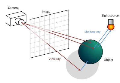
To perform physically-based rendering a simulation of light must be used that al-lows for realistic light transport between surfaces in a virtual scene. While other methods have been used, as shall be discussed in Section 2, the most common method used is ray tracing. Ray tracing is a method in which the light is simu-lated by a number of rays, each one containing a discrete amount of energy. As can be seen in Figure 1.2.1 these rays are then cast into the scene and intersected against the scene geometry, with behaviour such as reflectance and absorption dictated by physically-based functions, called bi-directional reflectance functions or BRDFs [Nic65], defined for each surface. These rays are then used to calculate how much light would reach a given receiver, typically an eye or camera. For a visual representation of this process refer to Figure 1.2.1.
Kajiya [Kaj86]. These extensions included effects such as shading from area light sources, complex BRDF modelling for correct specular and glossy reflection and refraction, indirect diffuse computations, caustics, participating media, motion blur, depth of fieldetc. all based on the simple recursive ray tracing computation. As can be seen in Figure 1.2.2 the results can be very realistic.
Image Camera
Light source
Object
View ray
[image:18.595.115.515.215.493.2]Shadow ray
Figure 1.2.1: This figure demonstrates the concept of ray tracing. A ray is cast from the camera through the image plane, passing through a particular pixel. This ray can then intersects the scene at a point. A further ray is then cast from this point towards the light to determine how much energy from the light arrives via this path, assuming it is unobstructed, otherwise the point is in shadow.
1.3
Interactive Global Illumination
(a) A model of a real building, Sponza [Dab10], relit to simulate a specific time of day.
(b) A scene composed of a number of models: the Stanford bunny and Buddha, Utah teapot and custom grass and enclosure. The custom models were created by hand while the others were cap-tured utilising laser scanning techniques. Light Probe courtesy of Paul Debevec [Deb10].
(c) A scene containing two mobius strip models
As we shall describe in detail in 3.1.1 and 3.1.2, interactive ray tracing has focused on the exploitation of coherency among primary rays, ones cast from or converging at a point in the scene. In contrast, to attain interactivity global illumination requires the computation of a large number of secondary rays, those that have already been reflected one or more times and therefore don’t share a common origin or similar directions. The inherent complexity of the computation combined with limited computational resources requires that new approaches be considered that leverage all the available computational power and make optimal use of it.
Figure 1.3.1: On the left side is an image that has been adaptively sampled, starting with tiles that are 4×4 pixels in size. The values at the four corners of each tile were computed and if deemed necessary the tile was further recursively subdivided, as needed, into four parts. This image was then interpolated, via bilinear interpolation, using the four corner values at each tile with the resulting image being shown on the right. Images courtesy of Kurt Debattista [Deb06].
in Figure 1.3.1 where adaptive sampling was used and the interior pixels of each tile were filled in via bilinear interpolation [Deb06].
Combining interactive ray tracing methods and existing off-line global illu-mination techniques with selective rendering, to accelerate the computation suf-ficiently for interactive rates, seems like a natural choice but there exist some fundamental issues which this thesis addresses. As mentioned above, interactive ray tracing methods are dependent on high levels of coherency to achieve their interactive rates, which is in direct conflict with selective rendering which is nat-urally incoherent due to the fact that it processes only select pixels in an image that may be completely spatially incoherent.
This thesis analyses and quantifies the impact that selective rendering has on interactive ray tracing. These results are then utilised to develop two novel interactive global illumination solutions along with novel data access control mechanism. The interactive global illumination solutions don’t rely on any pre-computation and are therefore suited for dynamic scenes where cameras, lights and objects can all be moved. Furthermore, a data access control mechanism is presented that presents a wait-free implementation geared towards highly par-allel and interactive systems. These solutions are all designed to function in an interactive context and serve as important steps towards reaching the final goal of a real-time solution, while being of interest to a number of the commercial fields mentioned previously.
1.4
Research Objectives
This thesis aims to combine selective rendering techniques and state-of-the-art interactive global illumination algorithms. The main research objectives of this thesis are:
• to analyse and quantify the impact of combining selective rendering tech-niques and interactive global illumination algorithms.
• to create a rendering system to implement and test these novel algorithms again against current state-of-the-art approaches.
1.5
Thesis Outline
The layout of this thesis is as follows.
Chapter 2: Background presents an overview of the concepts pertaining to realistic image synthesis as well as providing background on all the algo-rithms that will be covered in this thesis.
Chapter 3: Interactive Global Illumination provides a detailed literature review of interactive ray tracing and global illumination on both the CPU and GPU, as well as a discussion on the problems that the reliance on coherency poses to interactive global illumination algorithms that attempt to adaptively calculate the solution.
Chapter 4: Impact of Selective Rendering on Interactive Ray Tracing
analyses and quantifies the impact of selective rendering on interactive ray tracing and identifies where selective rendering can be applied to best effect.
Chapter 5: Adaptive Interleaved Sampling for Interactive Global Illu-minationbuilds on the work presented in the previous chapter to develop a novel global illumination algorithm calledAdaptive Interleaved Sampling. A generalisable approach that combines interleaved sampling with an adap-tive approach which uses efficient component-specific adapadap-tive guidance methods to drive the computation. The methodology employed while de-veloping this algorithm is also refined and presented as a framework that provides a structured approach when combing selective rendering methods and interactive global illumination techniques.
Chapter 6: Instant Caching for Interactive Global Illuminationtakes a previously off-line technique, irradiance caching, and develops an adaptive update method, using the methodology from the framework, to allow the solution to calculate diffuse interreflections at interactive rates. The design of the algorithm enables the extension of the spatial coherence of the irra-diance cache into the temporal domain, exploiting the temporal coherence to avoid wasteful computation by using selective techniques.
irra-diance cache in an interactive context in the previous chapter, that allows the irradiance cache to be shared among many threads on a shared memory parallel system without contention issues. This approach is evaluated to show its superiority over two traditional data access algorithms: a lock-based approach and a local write approach.
Background
This chapter introduces the fundamental concepts and knowledge needed to un-derstand the processes and methods behind the generation of physically accurate representations of virtual scenes.
2.1
Introduction to Rendering
This section begins with Section 2.1.1 where the physical quantities utilised in radiometry are introduced. Subsequent sections, Sections 2.1.2 and 2.1.3, discuss the interaction of light with objects within the virtual scenes and light’s transport through the scenes in the context of the rendering equation.
2.1.1
Radiometry
The goal of any local or global illumination algorithm is to calculate the distri-bution of light energy in a scene, be it the whole distridistri-bution or part thereof. To achieve this goal an understanding of the physical quantities that represent light energy is needed. Radiometry is the field of study that deals with the phys-ical quantities and measurements of light. This section provides a brief overview of the radiometric units used in the rest of this thesis, following the terms and terminology utilised in Dutre et al.[DBB06]. It should be noted that photomet-ric terms utilised in light perception are simply derived from their radiometphotomet-ric counterparts.
Radiant power or flux (Φ) is the primary radiometric quantity which is mea-sured in watts (joules/sec). Flux is not dependant on the size of the source or receiver or the distance between them. Flux simply expresses the total energy
flow at a surface per unit time.
Irradiance (E) is amount of incoming radiant flux per unit surface area, and is measured inwatts/m2. Radiosity (B) or radiant exitance is the outgoing radiant power per unit surface area. It is also measured in watts/m2.
Φ = dQ
dt E =
dΦ
dA B =
dΦ
dA
Radiance (L) is the most commonly used quantity in realistic image synthesis and denotes the flux per unit project area per unit solid angle, measured in
watts/(m2steradin). This is simply the flux coming in from a specific direction onto a small area.
L= d
2Φ
dwdAcosΘ
Transport theory, dealing with the mathematics governing the transfer of energy between media, can also be utilised to express the radiometric quantities in terms of a pointxand direction Θ whereL(x→Θ) denotes the radiance leaving a point
xin direction Θ. The relationships between Φ, E(x) andB(x) is examined below, where A is the total surface area and Ω is the total solid angle at each point on the surface. Φ = Z A Z Ω
L(x→Θ) cosθdwΘdAx
E(x) =
Z
Ω
L(x←Θ) cosθdwΘ
B(x) =
Z
Ω
L(x→Θ) cosθdwΘ (2.1.1)
For the remainder of this thesis radiance leaving point x in direction Θ will be represented as L(x → Θ) and radiance arriving at point x from direction Θ as
L(x←Θ).
2.1.2
Surface Interactions of Light
When light energy is emitted into a scene it interacts with a number of different objects by getting reflected, transmitted or absorbed at surfaces boundaries. A light reflectance model attempts to model these interactions, usually through the use of a function that attempts to reproduce the physical behaviour of the material.
Pure diffuse Pure specular Glossy
Figure 2.1.1: BRDF examples: The first case demonstrates pure diffuse or Lam-bertian reflection [Lam60], were light energy is scattered equally in all directions. The pure specular case reflects all incoming energy in one particular direction with no scattering. Finally the glossy case exhibits both diffuse and specular properties, scattering light but having a number of specific directions which are favoured.
Reflectance Distribution Function (BRDF). The BRDF (fr) is a function that describes the ratio of reflected differential radiance at a point x from direction Ψ to the differential irradiance in the outgoing direction Θ. A more generalised version of the BRDF function is one that has both an entrance and exit point, and models not only reflectance but also transmittance allowing for effects such as subsurface scattering [JC98], this function is called the Bidirectional Surface Scattering Reflectance Distribution Functions (BSSRDF) [Jen01]. Focusing on the BRDF, utilising the definitions from Dutre et al.[DBB06], which is denoted as fr(x,Ψ→Θ):
fr(x,Ψ→Θ) =
dLr(x→Θ)
dE(x←Ψ) =
dLr(x→Θ)
L(x←Ψ) cos(Nx,Ψ)dwΨ
(2.1.2)
where cos(Nx,Ψ) is the cosine of the angle formed by the normal vector Nx and incoming direction Ψ at point x. A common property of BRDFs is reciprocity where the value of the BRDF remains unchanged if the incident and exitant directions are interchanged so thatfr(x,Ψ→Θ) =fr(x,Θ→Ψ).
2.1.3
Light Transport
Having dealt with surface interactions of light energy this section examines the light transport in a virtual scene. The goal of the light transport is to compute the steady-state distribution of light energy within the scene. This computation accounts for the global aspect of the illumination model and as such is funda-mental to any global illumination algorithm. This model is represented as a mathematical equation termed the rendering equation [Kaj86]. For this equation it is assumed that participating media, such as smoke or fog, is not present and that light travels instantaneously. For each surface point x and each direction Θ the rendering equations returns the exitant radiance L(x → Θ). The exitant radiance is the sum of the emitted radiance from a the point x, described as
Le(x → Θ), and the reflected radiance described as Lr(x → Θ). The derivation of the rendering equation below follows Dutre et al. [DBB06].
L(x→Θ) =Le(x→Θ) +Lr(x→Θ) (2.1.3)
Utilising the definition from Equation 2.1.2 and integrating through, to take into light incoming from all directions on the hemisphere, gives:
Lr(x→Θ) =
Z
Ωx
fr(x,Θ↔Ψ)L(x←Ψ) cos(Nx,Ψ)dwΨ (2.1.4)
Equation 2.1.3 is substituted in to reach the final form of the rendering equation:
L(x→Θ) =Le(x→Θ) +
Z
Ωx
fr(x,Θ↔Ψ)L(x←Ψ) cos(Nx,Ψ)dwΨ (2.1.5)
Equation 2.1.5 is called the hemispherical formulation of the rendering equation. Another formulation which is widely used is the formulation that expresses the rendering equation in terms of the contribution all surfaces make to the reflected radiance. For this formulation, a visibility function V(x, y) is utilised, where
can reformulated as cos(Ny,−Ψ)rdA2
xy. This leads to the following formulation:
L(x→Θ) =Le(x→Θ)+
Z
A
fr(x,Θ↔Ψ)L(y← −Ψ)V(x, y)
cos(Nx,Ψ) cos(Ny,−Ψ)
r2 xy
dAy
This is more commonly written as:
L(x→Θ) =Le(x→Θ)+
Z
A
fr(x,Θ↔Ψ)L(y ← −Ψ)V(x, y)G(x, y)dAy (2.1.6)
where:
G(x, y) = cos(Nx,Ψ) cos(Ny,−Ψ)
r2 xy
The rendering equation, or parts of it, are utilised by most rendering approaches when attempting to get realistic results. From classical ray-tracing [Whi80] which would only sample along pure specular and transmitted paths to classical radios-ity that only used a perfectly diffuse BRDF [GTGB84] these approaches solved a part of the rendering equation.
algo-rithm is consistent, such as photon mapping, it converges towards the correct result given enough computational time.
While there are many other aspects of light transport, such as the influence of participating media, that affect the rendering equation these are simply out of the scope of this thesis. For a thorough overview of this area please consult Dutre et al.[DBB06]; Shirley and Morley [SM03].
2.2
Primary Rendering Techniques
Sections 2.2.1 - 2.2.3 introduce the three primary rendering techniques utilised in digital image synthesis: rasterisation, ray tracing and radiosity.
2.2.1
Rasterisation
Interactive computer graphics has largely been dominated by rasterisation algo-rithms. Rasterisation supports scenes composed of geometric primitives that are computed as polygons, directly or through on-demand polygonisation from other geometric primitives such as Non-Uniform Rational Basis Spline (NURBs). The rasterisation pipeline begins with a series of computations that transform the geometry into the view space, followed by a projection onto a 2D image view plane. Lighting is calculated and visibility is usually computed using z-buffer algorithms [Cat74]. Integrated within the z-buffer algorithm, to complete the pipeline is the rasterisation process. This is typically composed of polygon-fill algorithms, texturing and sometimes aspects of the lighting computation. Raster-isation has been favoured by the gaming industry and film industry [CCC87] due to its simplicity and rendering speed. Over the past decade real-time speeds have been accentuated further by dedicated graphics hardware such as the graphics processing unit (GPU). The GPU has also been utilised to compute ray tracing as well as global illumination solutions as discussed in Sections 3.1 and 3.2.
area lights [HLHS03], caustics [Wym08] and other lighting computations, al-though very often these are not physically-based but physically-inspired. Other methods can be applied for pre-computing non-specular effects, such as radios-ity [GTGB84] or PRT [SKS02] and its extensions [ZHL∗05, PWL∗07, IDYN07]. While these methods now support rigid-body dynamic scenes they, as yet, do not handle deforming objects.
Recently with the increase in computational power of the GPU, as well as the ability for shaders to generate new geometry, a number of more complex effects, such as depth of field [BK08], dynamic indirect lighting [SIMP06b, RGKS08, ML09], soft shadows [DL06, SGNS07], complex reflections [YYM05, EMDT06] and refractions [Wym05, OB07] have been added to the rasterisation pipeline. A comprehensive overview on interactive rendering methods using rasterisation is provided by Akeine-Moller et al. [AMH02].
2.2.2
Ray Tracing
The class of algorithms termed ray-tracing, introduced in Section 1.2 find their roots in the ray-casting methods of [App68] for computing surface visibility. This technique was used for hidden surface removal and involved shooting rays from a virtual camera into a scene and returning the closest object hit thus accounting for surface visibility.
on the simple recursive ray tracing computation.
Furthermore, ray tracing offers the option to be able to compute intersections directly with many different geometric types (without tessellation) and is easy to parallelise. The ability for ray-tracing to produce realistic images meant that software based around these algorithms was developed for use in realistic lighting simulations, see for example Ward [WRC88] and more recently has begun to be used in film production [Her04, Chr06]. For a comprehensive overviews of ray tracing methods refer to Glassner [Gla95]; Shirley and Morley [SM03].
2.2.3
Radiosity
Classical radiosity was introduced into the computer graphics field from thermal engineering by Goral et al. [GTGB84]. This view-independent finite-element method solves the global illumination component of the rendering equation for perfectly diffuse surfaces and only handles diffuse to diffuse interactions. It does this by discretising the scene into a series of patches and computing the radiosity for each patch, which is the total power leaving the surface of the patch. This computation is a system of N simultaneous linear equations where the fraction of power arriving at one patch from another is called the form factor. The computation of the visibility between patches is potentially the most expensive computation in the radiosity pipeline and a number of approaches have been proposed to tackle the problem.
The most popular approach to solve the visibility problem is to use projection. The form factor with any surface, calculated from a particular point, is simply the projection of that surface onto the hemisphere around the point. The hemi-cube method [CCWG88] uses rasterisation to project the hemisphere on the faces of a hemicube using techniques such as hidden surface removal to accelerate the computation. Other methods to solve the visibility problem use different projections and ray casting techniques, further details can be found in Sillion and Puech [SP94]; Ashdown [Ash95].
meth-ods that replace form factor computation with form factor sampling, improving both the computational speed and reducing memory usage [Bek99, DBB06].
Solving the radiosity equation for other surface interactions, such as glossy or specular, has been attempted [AH93] but the solution required a more complex surface subdivision approach and form factor calculation, increasing computa-tional time substantially. Most other solutions that utilise radiosity to solve the rendering equation [Kaj86] do so by using a hybrid solution that incorporates ray tracing to compute the specular components. Some of these methods are covered in more detail in Sections 3.2.1.2 and 3.2.2.1.
View independent radiosity has a number of advantage over ray tracing. Lighting only needs to be computed once, and can then be re-used for inter-active walkthroughs of static scenes, where the geometry and lighting do not change.
2.3
Accelerating Rendering
In this section a number of techniques are examined that are used to accelerate some aspect of rendering. Section 2.3.1 examines how the rendering equation can be broken up into a number of components and how algorithms can target specific components to reduce the overall computational time. In Section 2.3.2 adaptive and progressive approaches are investigated which focus computational power, using some form of guidance, in areas of highest benefit. Section 2.3.4 examines dynamic acceleration data structures and their application and contribution to interactive ray tracing. Finally Section 2.3.5 introduces the irradiance cache, extended in Chapters 6 and 7, and its current extensions and uses.
2.3.1
Component-based Rendering
Figure 2.3.1: A Cornell Box scene split into a number of components: (top-left) direct, (top-middle) indirect diffuse (top-right) pure specular, (bottom-(top-left) glossy (bottom-middle) transmitted (bottom-right) reflected. Images courtesy of Kurt Debattista [DSSC05].
paths.
More recently approaches such as Stokes et al. [SFWG04] and Debattista et al. [DSSC05] have combined component-based approaches with perceptual ren-dering, covered in Section 2.3.2. Stokes et al. [SFWG04] presented a perceptual metric, which was combined with path tracing, to predict the importance of the components for a given scene. The metric used the primary rays of the path tracing computation to collect information about the scene, this information combined with the metric was then used to allocate resources based on percep-tual importance. In Debattista et al. [DSSC05] a component regular expression (crex) was introduced that allowed for fine grained control with regard to the components that were computed and the order they were computed in, see Fig-ure 2.3.1. Combining thecrex with a perceptual metric allowed for the reduction of computational complexity while maintaining perceived visual quality.
2.3.2
Selective-Rendering
Selective rendering is defined by Debattista [Deb06] as “those techniques which require a number of rendering quality decisions to be taken and acted upon prior
to, or even dynamically during the actual computation of any image or frame
2.3.2.1 Rasterisation
Techniques applicable to off-line selective rendering go back to early work done on level of detail by Clark [Cla76]. While most techniques stored a distinct version of the model for each level of detail and discretely switched between them the work presented in Luebke and Hallen [LH01] utilised an adaptive perceptual metric to select an appropriate level of detail. Bergman et al. [BFGS86] presented a different approach in which the complexity of the shading was adaptively adjusted on a per polygon basis, from displaying only vertices to using Phong shading with anti aliasing. The focus of this thesis is on ray tracing and therefore for further comprehensive overviews of rasterisation-based approaches please refer to Akenine-Moller and Haines [AMH02]; Luebke et al. [LWC∗02]
2.3.2.2 Ray tracing
within the block. This occurred recursively but at any point the image could be reconstructed using the DCM. The work was further extended in Farrugia and P´eroche [FP04] where a perceptual metric rather than the DCM was used. Direct lighting can also be selectively calculated using techniques such as those presented in Ward [War91b] and Shirley et al. [SSW∗06]. For Ward [War91b] the contribution of multiple lights was sorted based on contribution potential, which was based on criteria such as: distance of light from surface, light intensity and size of light source. The lights with the highest potential had shadow rays calculated for them until a certain threshold was reached after which a statistical simulation, based on previous visibility tests, was used to approximate the rest of the contributions. In Shirley et al. [SSW∗06] the scene was divided into cells that stored differentiated between lights that considered important and ones that weren’t, which were then sampled accordingly. Jin et al. [JIC∗09] provided an adaptive and selective approach to tackle supersampling in an interactive ray tracing context where both image-space and object-space attributes were used to calculate a priority which then guided the computation.
2.3.2.3 Perception
components where rendered in higher detail. In Cateret al.[CCW03]; Sundstedt
[image:38.595.114.524.255.461.2]et al. [SCM04] saliency maps and task maps where used to vary the number of samples calculated in a global illumination framework based on theRadiance ren-derer by Ward [War94]. Sparse sampling methods such as Walteret al.[WDP99], all covered in detail in Section 3.2.1, also used adaptive techniques to focus com-putation in areas of importance. For an comprehensive overview of recent work in perceptually adaptive graphics please refer to O’Sullivanet al.[OHM∗04]; De-battista [Deb06].
Figure 2.3.2: An adaptively rendered scene, showing on the left, utilising an Aleph map [YPG01], shown on the right, as guidance. Images courtesy of Hector Yee [YPG01].
2.3.3
Interleaved Sampling
When correlated samples are utilised they are faster to generate and more coher-ent but this is at the expense of visible sampling patterns and structured noise. Decorrelation of these samples on the other hand increases variance and therefore generates random noise. Interleaved sampling [KH01] combats this by creating an interleaved sampling pattern. This is done by blending smoothly between both regular and irregular sampling, interleaving the samples of a regular grid, which are correlated, in an irregular way to maintain coherency but reduce the aliasing of the sampled image.
rasteri-sation. In the paper by Waldet al.[WKB∗02] it was used to accelerate the global illumination solution by allowing only a subset of the virtual point lights that were generated to be sampled per pixel. Segoviaet al.[SIMP06b] also proposed a real-time method for interleaved sampling where they introduced a technique to maintain coherency between neighbouring pixels by splitting the rendered image into a number of sub-buffers. These sub-buffers contain only pixels from a spe-cific part of the interleaved sampling pattern. These are then later recombined and filtered taking into account discontinuities, see Figure 2.3.3. In Sloan et al.[SGNS07] and Forestet al. [FBP08] interleaved sampling is used to accelerate shadow generation on the GPU by reducing the overall number of samples that need to be calculated.
Figure 2.3.3: An example of the structured noise created by interleaved sampling is shown on the left, this noise can be greatly reduced, as can be seen on the right. This is achieved by utilising a correctly-sized filter kernel, same size as that of the interleaved sampling pattern, along with discontinuity buffering [WKB∗02].
2.3.4
Dynamic Acceleration Structures
please refer to Havran [Hav01];Hunt et al.[HMS06]; Havranet al.[HHS06]; Wald
et al. [WBS07].
When ray tracing developed the ability to ray trace scenes at interactive rates on single machines [RSH05, Wal04] a significant factor, besides faster hardware, was more effective acceleration structures and enhanced traversal algorithms. At the time kd-trees were observed to give the best performance [Hav01] especially when using the Surface Area Heuristic (SAH) [MB90] during construction.
Three primary strategies were identified at that time that enabled interactive ray tracing:
1. Avoid rebuilding the kd-tree [LLAm01, WKB∗02, GFW∗06].
2. Utilise and optimise other acceleration structures such as:
• Grids [RSH00, WIK∗06].
• Bounding Volume Hierarchies (BVHs) [LYTM06, WBS07].
• Hybrid structures [WK06].
3. Optimise the construction of SAH based kd-trees, primarily by parallelising and optimising the evaluation of the expensive SAH cost function [HMS06, PGSS06, CKL∗10].
Shevtsov et al. presented a fast and highly parallel kd-tree construction algo-rithm that allowed for a full kd-tree rebuild of an entire scene every frame [SSK07], Wald et al. published two papers that redirected a large portion of the research towards BVHs. The first presented an optimised method for firing large ray packets (several times bigger than the SIMD width) through a BVH [WBS07], while the second showed how fast kd-tree rebuilding techniques could be applied to BVHs and how these methods provided almost ten times more speed-up when utilised in this context [Wal07]. At the same time Yoon et al. presented an algo-rithm to selectively restructure a BVH based on the output of two new metrics that measured the restructuring benefit and culling efficiency [YCM07]. Finally Waldet al. presented three new methods that allowed for fast, parallel and asyn-chronous construction of BVHs; a full rebuild using a fast binning approach when evaluating the SAH cost function; a parallel version of the binned build; and, a asynchronous build that occurs over multiple frames [WIP08].
More recently a number of publications have investigated building a BVH so that SIMD utilisation can be exploited not by tracing multiple rays against one node, but by tracing one ray against multiple nodes of the structure. Ernst et al.[EG08], Dammertz et al.[DHK08] and Waldet al. [WBB08] have all recently presented techniques for the construction of a BVH with more than two branches, generally four, for each node.
All the work above has focused on construction of acceleration structures on the CPU. Recently new work has dealt with construction acceleration structures entirely on the GPU. A technique for construction a full kd-tree entirely on the GPU was presented by Zhou et al. [ZHWG08]. This method constructs nodes in a breadth-first order to exploit the significant streaming performance that the GPU provides. In the same vain Lauterbach et al. presented an algorithm for BVH construction on the GPU, providing two versions: one general version for use with methods such as collision detection, and a specialised version tuned for ray tracing [LGS∗09]. This approach was extended in Pantaleoni and Luebke [PL10] where two construction approaches were presented, a hierarchical variation of the construction approach along with an SAH-optimised variation.
2.3.5
Irradiance Caching
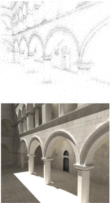
updating the octree topology. An example of the resulting sample locations can be seen in Figure 2.3.4. By caching the results of the expensive indirect diffuse computations an order of magnitude decrease in the overall computation time was observed. This caching approach has been extended for accelerating the computation of other components such as subsurface scattering [KLC06] as well as participating media [JDZJ08].
Figure 2.3.4: The top image show a vi-sualisation of samples present in an irra-diance cache, with the resulting rendered image at the bottom. Images courtesy of Jaroslav Kˇriv´anek [KGW∗07].
The irradiance cache has been ex-tended in many ways, the first of these was the use of irradiance gradients [WH92]. These gradients, both rota-tional and translarota-tional, were stored along with the cache samples and used to improve performance and reduce ar-tifacts by adjusting the shape of the search radius which was valid during range searches. A new approach for calculating the error metric, which dic-tates when new samples are created and when they are extrapolated/in-terpolated, was introduced by Tabel-lion and Lamorlette [TL04]. They also demonstrated how the irradiance cache had been utilised in accelerat-ing global illumination in a framework used for rendering imagery for com-puter generated movies. Krivanek et al. [KGBP05] presented the radiance cache, which extended the caching of diffuse interreflections by allowing glossy interreflections to be cached as well. This work was then further
indirect lighting [GKBP05].
Another approach used to accelerate the irradiance cache is to run it on a parallel system. In these systems each thread or process might evaluate new irradiance values and add them to the cache. To increase efficiency the cache must be shared among all the processes, to avoid work replication, making it a shared data structure. This requires some form of access control mechanism, see Section 2.4, which ensures that the data is accessible, updatable, doesn’t be-come corrupted and that whose overheads do not compromise performance or efficiency. In a distributed memory system multiple copies of the structure are maintained and need to be synchronised. In the Radiance distribution [War94] this was achieved by using the Network File System (NFS) for concurrent access to the cache. It was important to use an efficient file locking manager as oth-erwise contention would lead to poor performance. Another approach presented by Koholka et al. [KMG99] was to broadcast cache values amongst processors, each time 50 samples were calculated by a slave node. Robertsonet al.[RCLL99] presented a centralised parallel version of Radiance where the calculated cache values were sent to a master node whenever a threshold was met. Each slave node then collected the values from the master node at regular intervals. Finally Debattista [Deb06] proposed restricting diffuse irradiance evaluations to a sub-set of the available nodes and synchronising the cache among these at a higher frequency than with the remaining nodes.
the photons with the final gathering rays and all the mechanisms related with it to manage anchor creation, update and deletion, on top of photon mapping and irradiance caching. Finally Gautronet al.[GBP07] presented a temporal solution that catered for changes in the temporal domain and included computation of a temporal gradient. This method predicted the incoming lighting and how it would affect the cached samples, with the drawback being that paths through the cache needed to be known before hand to correctly predict illumination. It should be noted that all the methods presented above, the original irradiance cache, the extensions as well as the distributed and temporal approaches all worked off-line and were not utilised in any interactive systems.
2.4
Synchronisation
This section will examine the different approaches to access control mechanisms for shared data structures, and their relative advantages and disadvantages. Tra-ditionally, access control to shared memory data structures is maintained via mutual exclusion, a property that dictates that only one thread or process can access a particular piece of data at a time. The area of code where mutual ex-clusivity must be maintained, and therefore concurrent access cannot occur, is termed a critical section.
2.4.1
Blocking
Blocking occurs when locking mechanisms, such as semaphores, mutexes and monitors, are used to guard critical sections [Dij68]. When one process attempts to acquire a lock that is already held it will block until the lock is free.
2.4.2
Busy-waiting
When frequent access to a shared data structure may be required, the cost of blocking may be prohibitive. In this case if another process lies within the critical section a process is made to busy-wait instead of block, by continuously checking if the lock is available, until access is allowed. An example of a busy-wait or spinning technique is the spin lock. Such control mechanisms incur overheads, such as serialisation of accesses to the shared data structure, but avoid expensive context switching or re-scheduling that occurs for blocking mechanisms. Busy waiting of frequently-accessed resources leads to contention which can drastically reduce performance as the number of threads increases [ALL89]
2.4.3
Non-blocking
An alternative is algorithms that utilise non-blocking synchronisation, an ap-proach which avoids mutual exclusion by carefully ordering instructions. These algorithms can eliminate code serialisation by removing all critical sections and also reduce contention [HS08]. Non-blocking algorithms are classified in three main categories: obstruction-free, lock-free and wait-free.
The weakest form of the non-blocking approaches take the form of obstruction-free methods. An algorithm is obstruction-obstruction-free if it can guarantee that a thread can complete in finite time if it operated in isolation (i.e. with all other threads suspended). This requires that any partially-completed operation can be aborted and the changes made rolled back at any time.
Lock-free algorithms guarantee that at least one among a set of concurrent threads will complete in finite time. This allows individual threads to starve but guarantees system-wide throughput. This process generally occurs in four phases: completing one’s work, assisting an obstruction, aborting an obstruction and waiting. Completion of assigned work is complicated by the possibility of assistance and abortion, but is generally the fastest path to complete execution. The decision whether to assist, abort or wait if an obstruction in encountered is typically the most complex part of a lock-free algorithm. All lock-free algorithms are obstruction-free.
Listing 2.1: “Fetch and Add” (XADD) and “Compare and Swap” (CAS)
1 atomic XADD(address location)
2 {
3 int value = *location;
4 *location = value + 1;
5 return value
6 }
7
8 atomic CAS(address location, value cmpVal, value newVal)
9 {
10 if ( *location == cmpVal )
11 {
12 *location = newVal;
13 return true;
14 } else return false;
15 }
avoid starvation, deadlock and livelock and priority inversion and are ideal for multiprogrammed multiprocessors. All wait-free algorithms are also lock free. It has been shown that that all algorithms can be implemented in a wait-free manner [Her88]. While many approaches that transform serial code, called universal constructions, have been presented these approaches generally result in reduced performance, even when compared to a standard blocking approach.
2.4.4
Atomic Primitives
Interactive Global Illumination
This chapter provides a thorough review of both interactive ray tracing and global illumination on both the CPU and GPU. This work builds on the render-ing concepts introduced in Chapter 2 and details the primary area of research that pertains to this thesis, interactive global illumination. The information pre-sented here pertaining to the developments in this field is then utilised during the development and presentation of a number of novel interactive global illumination algorithms further detailed in Chapters 5 - 7.
This chapter begins by introducing interactive ray tracing (IRT) and examines how the CPU (Section 3.1.1 and GPU 3.1.2) are utilised in computing interactive ray tracing solutions. In Section 3.2 interactive global illumination algorithms are examined in detail investigating both CPU (Section 3.2.1) and GPU (Section 3.2.2) methods. Section 3.3 examines the role coherence plays in interactive ray tracing and how this coherence is exploited to increase computational throughput and how this can be combined with sparse sampling methods. Finally Section 3.4 provides a summary of the chapter.
3.1
Interactive Ray Tracing
This section examines interactive ray tracing which encompasses systems and algorithms that produce Whitted-style [Whi80] results at interactive rates, see Section 2.2.2 for an overview of Whitted-style ray tracing. Interactive in this context refers to the ability of the system to complete the computation of the solution and update it at least once per second. These systems focus on coherent primary rays, those that leave the camera and strike the scene, as well as a very limited number of coherent secondary rays for effects such as hard shadows,
reflections and refractions.
These systems, generally, form the basis or structure for interactive global illumination systems. These global illumination systems require even a larger number of rays, additional secondary rays, to be traced. These allow for effects such as diffuse interreflections, soft shadows, motion blur and many others to be calculated. The ability to generate the primary rays at interactive rays is therefore critical for allowing interactive global illumination systems to function.
3.1.1
CPU Algorithms
This section focuses on the detailed examination of CPU-based interactive ray tracing systems and algorithms. These systems are an important part, and form the basis, of interactive global illumination systems. This is due to the fact that primary rays must be generated at interactive rates if the system it to be interactive as a whole.
3.1.1.1 Systems
Initial work on interactive ray tracing occurred as early as 1995 when distributed multiprocessor machines, referred to as supercomputers, where utilised in an attempt to achieve interactive rates for ray tracing systems. To evaluate the suitability of a custom-built 64 processor machine as an interactive ray tracing system Keates and Hubbold utilised a custom ray tracer employing a regular grid as an acceleration structure [KH95]. Interactive rates of one to five frames per second (fps) where achieved on as few as 32 processors but only by reverting to simple ray casting by disabling secondary rays (such as shadow, reflection and refraction rays) and using progressive rendering. Unlike Keates and Hubbold, Muuss [Muu95] utilised a system that contained 96 processors, along with a commercial ray tracing package that used a nonuniform binary space partitioning (BSP) tree [FKN80]. Interactive and near-interactive, between a half and two frames per second, rates were achieved for a resolution of 720×486 when rendering three distinct spectral bands.
hi-erarchy they demonstrated interactive rates, between one and twenty frames per second. The results presented showed a highly scalable system that could render a one gigabyte volume dataset, including shadows, at ten frames per second. This work was then extended into *-Ray by Parker et al. where the ability to render objects other than isosurfaces (such as spheres, polygons and spline models) was added [PMS∗99]. Frameless rendering [BFMZ94], an approach where the display is no longer presented as a time series of frames but rather as a single frame where different regions are updated over time, was also employed to speed-up the computation and allow for interactive rendering on as few as eight processors.
While the previous approaches utilised custom or high-end shared-memory supercomputers, with costs in the millions of dollars, Wald et al. presented a system running on a cluster of four commodity desktop machines [WSBW01]. By carefully exploiting spatial coherence at an object and image level along with the use of SIMD instructions [Int03] and optimised traversal and intersection routines this work presented interactive rates for scenes of up to 8 million triangles. In Waldet al.[WSB01] this work was further extended to handle much larger scenes, up to 12.5 million triangles. This was achieved via simple pre-process step in which a scene database is generated and distributed to all the clients, which then fetch and cache BSP voxels as required. This combined with latency hiding and load balancing allowed for interactive rates on a cluster of nine dual-core machines. Another system that presented the visualisation of large datasets was from Demarle [DPH∗03]. This system was derived from the earlier mentioned *-Ray architecture [PMS∗99] and combined this with techniques from [WSB01] while building a better system for storage of the distributed data. This allowed interactive rendering of a 7.5GB dataset.
Djeu et al. are covered in greater details in Section 3.2.1 when interactive global illumination is examined.
Figure 3.1.1: The Manta interactive ray tracer rendering 2.8 million particles as individual spheres along with the tem-perature field as a volume, all at 15 to 20fps on a single multi-core desktop PC.
Image courtesy of James Bigler [BSP06].
Bigler et al.[BSP06] presented the software architecture of their interac-tive ray tracer, Manta, and described its application in engineering and sci-entific visualisation, for an example refer to Figure 3.1.1. Their empha-sis was on design considerations and differences between an interactive and batch rendering system with a focus on a high degree of parallelism and flexibility along with specific optimi-sations such as instruction-level par-allelism via SIMD [Int03] and packet-based acceleration structures. This work was also the basis of OptiX a real-time GPU-based ray-tracer which is covered in greater detail in Section 3.2.2. RTfact developed by Georgiev
at al. focused on a template-based li-brary consisting of packet-centric com-ponents combined into an efficient ray tracing framework. Generic design ap-proach with loosely coupled algorithms
and data structures allows for easy integration of new algorithms with maximum runtime performance [GS08]. Here, unlike Manta which relied on very low-level optimisations throughout the code-base, RTfact hid this complexity with the use of templates and higher level primitives.
3.1.1.2 Algorithmic enhancements
evaluating the corner rays, using SIMD instructions to further accelerate this. Other systems such as the one presented by Reshetov et al. [Res06] used sim-ilar concept of combining rays into beams or shafts. Intersecting these beams allowed for individual rays to start traversing the accelerating structure at some node deep inside the tree, saving computation and traversal time. While the previous approaches only worked for coherent groups of rays with shared origins Reshetov presented a new traversal algorithm for incoherent groups of rays. This approach, unlike splitting the rays into coherent subgroups, allowed for rays with completely different directions to be traced together reducing intersections by up to 50%. Other methods for culling entire ray packets using geometric and interval arithmetic were presented by Boulos et al. [BWS06]. Approaches for culling ray packets against triangles, axis-aligned bounding boxes (AABB) and spheres using interval arithmetic, corner rays and bounding planes where shown. Reshetov et al. presented further work on packet culling by proposing a system where special transient frusta where generated every time a leaf of an acceleration structure was traversed by a packet of rays [Res07]. These frusta contained the intersection of active rays with the leaf node allowing for the elimination of 90% of all potential intersection tests along with a tenfold reduction in the size of the acceleration structure while achieving better overall performance.
3.1.2
GPU Algorithms
GPU-based algorithms share a number of similarities to their CPU-based coun-terparts but due to the rapidly evolving GPU architecture are much more reliant on specific hardware optimisations and features to achieve interactive results. While borrowing heavily from the CPU-based systems they need to be examined in conjunction with the CPU-based approaches to have a full overview of the field of interactive ray tracing.
3.1.2.1 Systems
spa-tially coherent triangles, due to this scenes with highly incoherent ray-trees were problematic. Also the communication between CPU and GPU proved to be a bottleneck as triangle and ray data needed to be converted and sent to the GPU and results read back over the AGP bus, which is limited to 250 MB/sec.
At the same time Purcell et al. [PBMH02] had also developed a GPU-based ray tracer, the primary difference being this implementation performed more work on the GPU, specifically eye-ray generation and acceleration structure traversal. The acceleration structure chosen was a grid, which was stored in a 3D tex-ture and traversal was performed using the 3D-DDA [FTI86] with a multi-pass approach. The shading did not use the rasterisation pipeline directly but im-plemented more complex secondary effects such as shadow casting and 2-bounce path tracing. While this approach presented a more complete GPU-based ray tracing pipeline the approach assumed that the acceleration structure for the geometry was already generated before rendering began, making the method un-suitable for dynamic scenes. Also due to the fact that four different pixel shaders: for ray spawning, ray traversal, ray-triangle intersection and shading were used and that the rays are were different phases, peak GPU performance was limited to 10% [CHCH06]. Further research has extended this work [Chr04, TSr05] but all the attempts suffered from the same drawback and did not exploit the full computational capabilities of the GPU.
Due to the recent developments involving complex data structures, adaptive techniques and complex shading work has once again focused on the creation of systems. OptiX is such a system, based on the Manta ray tracer [BSP06], it is a general purpose ray tracing framework designed to run on state-of-the-art GPUs [PBD∗10]. Using a domain-specific just-in-time compiler it generates cus-tom ray tracing kernels by combining user-supplied programs for functions such as ray generation, material shading and scene traversal. These kernels are highly optimised at compile time allowing for interactive rates even when complex shad-ing models are used. The drawbacks of this framework are that the functionality is limited to NVIDIA GPUs, has a relatively fixed-stage pipeline and in-built acceleration structure and the code must be written in CUDA [GGN∗08].
3.1.2.2 Acceleration Data Structures
that other structures, such as kd-trees and BVHs, had numerous advantages in a number of different scenarios [Hav01, WKB∗02]. Ernst et al. [EVG04] were the first to implement a kd-tree traversal on the GPU, their implementations main limitation was that it required a fixed maximum stack depth. Foley and Sugerman [FS05] extended this work and demonstrated two new approaches for stack-less traversal of kd-trees on the GPU. Their results showed that for scenes with objects at different scales the kd-tree approach was up to 8 times faster than a uniform grid but still an order of magnitude slower than the best CPU approaches. They identified load balancing and data recirculation as the core issues that were behind this disparity in performance. Horn et al. [HSHH07] further extended this approach to use a single pass by using GPU branching and looping. Further work on stack-less kd-tree traversal was demonstrated by Popov
et al. in which they eliminated stack usage entirely and reduced the number of traversal steps required [PGSS07]. This work, while only benefiting CPUs moderately, improved GPU performance greatly allowing for over 16 million rays per second with moderately complex scenes involving secondary rays and complex shading.
Early work on BVH traversal and construction was performed by Thrane and Simonsen [TSr05] and Carr et al. [CHCH06]. In Thrane et al. [TSr05] the algo-rithms suffered from the same drawbacks experienced in Purcellet al.[PBMH02], as they used the same approaches as they did for the kd-tree traversal with the hierarchy still being constructed on the CPU. Carr et al.[CHCH06] constructed and traversed their hierarchy on GPU but it required a large amount of off-line pre-processing of the meshes. To optimise the traversal for large scenes [GPSS07] demonstrated a parallel packet-based algorithm using a shared stack that allowed for the ray tracing of a 12.7 million triangle scene on the GPU at interactive rates, including the generation of shadows and shading. The traversal was CPU-based but accurately approximated the surface area heuristic using streamed binning while still being one order of magnitude faster than previously published results. At the same time Roger et al. [RAH07] presented an acceleration structure that fully supported dynamic animated scenes. It combined concepts from beam trac-ing [HH84] and the hierarchical approaches such as the ones used in Arvo and Kirk [AK87] and Ghazanfarpour and Hasenfratz [GH98] using a ray-space hier-archy combined with breadth-first ray tracing [NO97].
![Figure 2.3.2:An adaptively rendered scene, showing on the left, utilising anAleph map [YPG01], shown on the right, as guidance](https://thumb-us.123doks.com/thumbv2/123dok_us/9646943.466863/38.595.114.524.255.461/figure-adaptively-rendered-scene-showing-utilising-analeph-guidance.webp)
![Figure 3.1.1: The Manta interactive raytracer rendering 2.8 million particles asindividual spheres along with the tem-perature field as a volume, all at 15 to20fps on a single multi-core desktop PC.Image courtesy of James Bigler [BSP06].](https://thumb-us.123doks.com/thumbv2/123dok_us/9646943.466863/50.595.323.520.135.424/figure-interactive-raytracer-rendering-particles-asindividual-perature-courtesy.webp)