warwick.ac.uk/lib-publications
A Thesis Submitted for the Degree of PhD at the University of Warwick
Permanent WRAP URL:
http://wrap.warwick.ac.uk/87867
Copyright and reuse:
This thesis is made available online and is protected by original copyright.
Please scroll down to view the document itself.
Please refer to the repository record for this item for information to help you to cite it.
Our policy information is available from the repository home page.
A Discrete Model for Patterning of Tensile Fabric
Structures
Stuart Gale MEng
Thesis submitted to the University of Warwick
for the degree of Doctor of Philosophy in Engineering
School of Engineering
University of Warwick
I Table of Contents
Table of Contents ... I
List of Figures ... VIII
List of Tables ... XVI
Acknowledgements ... XVII
Declaration ... XVIII
Abstract ... XIX
List of Symbols ... XX
List of Abbreviations ... XXVI
1 Introduction ... 1
1.1 Introduction to tensile fabric structures ... 1
1.1.1 Design process ... 3
1.2 Form-finding ... 4
1.2.1 Minimal surfaces ... 5
1.3 Patterning ... 5
1.4 Architectural fabrics, types and composition ... 6
1.4.1 Numerical modelling ... 8
1.5 Problem statement and scope ... 9
1.6 Scope, research objectives and contributions ... 9
1.7 Structure of Thesis ... 11
II
2 Literature review ... 13
2.1 Patterning ... 13
2.1.1 Mathematical basis of patterning ... 13
2.1.2 Computational pattering – the 5-step process ... 14
2.1.3 Subdivision of the membrane ... 15
2.1.4 Flattening ... 15
2.1.5 Stress reduction... 17
2.1.6 Compensating for pre-stress ... 20
2.1.7 Assembly of cutting patterns ... 21
2.1.8 Integrated approaches, optimisation and genetic algorithms ... 22
2.1.9 Patterning – research objectives identified ... 22
2.2 Numerical modelling ... 24
2.2.1 Behaviour of architectural fabrics ... 24
2.2.2 Continuum models and Finite Elements ... 28
2.2.2.1 Continuum models ... 28
2.2.2.2 Implementation by Finite Elements ... 30
2.2.2.3 Drawbacks of continuum modelling ... 31
2.2.3 Discrete models ... 32
2.2.3.1 Deformation modes in discrete models ... 34
2.2.4 Numerical modelling for patterning - research objectives identified ... 36
III
2.4 Identified gaps in knowledge ... 38
2.5 Research objectives and consequent direction of this thesis ... 39
2.6 Research methodology ... 40
2.7 Contributions to knowledge ... 41
3 Development of discrete element model ... 42
3.1 Proposed discrete element model ... 43
3.1.1 Treatment of tensile deformation... 44
3.1.1.1 Strain calculation ... 45
3.1.1.2 Stress calculation ... 46
3.1.1.3 Element width calculation ... 47
3.1.1.4 Non-rectangular edge geometries ... 49
3.1.1.5 Force from stress and width... 50
3.1.1.6 Forces applied to nodes ... 50
3.1.2 Treatment of shear deformation ... 51
3.1.2.1 Remarks on methods of modelling shear in discrete models ... 51
3.1.2.2 Shear strain between elements ... 53
3.1.2.3 Shear stress ... 54
3.1.2.4 Shear forces and fabric response ... 54
IV
3.1.3.2 Calculation of the corner forces using the proposed discrete model ... 59
3.1.3.3 Comparison of approaches ... 65
3.2 Analysis by Dynamic Relaxation ... 66
3.2.1 Dynamic relaxation with kinetic damping ... 66
3.2.1.1 Governing equation of motion and iterative procedure... 66
3.2.1.2 Kinetic damping by identification of kinetic energy peaks ... 69
3.3 Computational implementation ... 73
3.4 Summary ... 77
4 Proposed patterning method ... 79
4.1 Method of determining the cutting pattern ... 80
4.1.1 Subdivision of the form-found membrane shape ... 81
4.1.2 Flattening ... 84
4.1.2.1 Geodesic meshing of the 3D panels ... 84
4.1.2.2 Flattening methods ... 87
4.1.2.3 Flattening by direct projection ... 87
4.1.2.4 Flattening by unrolling with a single spine of elements ... 88
4.1.2.5 Flattening by unrolling with two spines of elements ... 91
4.1.3 Integrated stress reduction and compensation by dynamic relaxation ... 95
4.2 Proposed method of cutting pattern assembly and evaluation ... 97
4.2.1 Orthogonal re-meshing of planar panels ... 98
V
4.2.1.2 Factors affecting the suitability of the orthogonal mesh ... 100
4.2.2 Assembly of orthogonally meshed panels ... 103
4.2.2.1 Mapping the panels ... 104
4.2.2.2 Joining the panels ... 107
4.2.3 Equilibrium finding of the assembled mesh by dynamic relaxation ... 110
4.3 Summary ... 110
5 Application of the method to examples and results ... 113
5.1 Introduction ... 113
5.2 Flattening, stress reduction and compensation results ... 114
5.2.1 Specification for geometry from Linhard et al. [6] ... 114
5.2.1.1 Method used by Linhard et al. [6] ... 115
5.2.1.2 Patterning conducted by the author ... 115
5.2.2 Stresses incurred through flattening for geometry from Linhard et al. [6]116 5.2.2.1 Axial stresses incurred ... 117
5.2.2.2 Shear stresses incurred ... 120
5.2.2.3 Comparison of flattening methods ... 122
5.2.3 Residual stresses after stress reduction and compensation for geometry from Linhard et al. [6] ... 123
5.2.3.1 Residual stresses excluding the shear stiffness of the fabric ... 123
5.2.3.2 Residual stresses including the shear stiffness of the fabric ... 126
VI
5.2.4.1 Cutting patterns generated without including the shear stiffness of the fabric
131
5.2.4.2 Cutting patterns generated including the shear stiffness of the fabric ... 132
5.2.4.3 Comparison of cutting patterns ... 134
5.2.5 Specification for the geometry from Moncrieff & Topping [4] ... 135
5.2.5.1 Method used by Moncrieff & Topping [4] ... 135
5.2.5.2 Patterning conducted by the author ... 135
5.2.6 Residual stresses after stress reduction and compensation, and final cutting pattern shapes for Moncrieff & Topping [4] ... 136
5.2.6.1 Residual stresses without including the shear stiffness of the fabric ... 136
5.2.6.2 Residual stresses including the shear stiffness of the fabric ... 137
5.2.6.3 Comparison of cutting patterns ... 139
5.3 Pattern assembly results ... 139
5.3.1 Comparison with pattern assembly results from Linhard et al. [6] ... 140
5.3.2 Comparison with pattern assembly results from Moncrieff & Topping [4]143 5.4 Conditions affecting the analyses of the pattern assembly ... 146
5.4.1 The effect of including the shear stiffness of the fabric throughout patterning 147 5.4.2 Ill conditioning of shear elements ... 151
5.4.3 Necessity for the triangulation of the mesh at the boundary ... 156
5.5 Summary ... 166
VII
6.1 Summary of thesis ... 168
6.2 Conclusions ... 169
6.2.1 Limitations of the work ... 172
6.3 Future work and implications for engineering practice ... 173
VIII List of Figures
Figure 1.1 – Example of a tensile fabric structure. Santa Fe Opera Cantina, California ... 1
Figure 1.2 - Surfaces with anticlastic and synclastic curvature ... 2
Figure 1.3 – Woven fabric structure ... 7
Figure 2.1 - Unfolding of a panel to the plane. Note that across the width, the panel is
represented by just a single triangular element ... 16
Figure 2.2 - Reduction of stresses using the structural solution - adapted from Linhard et al. [6]
... 19
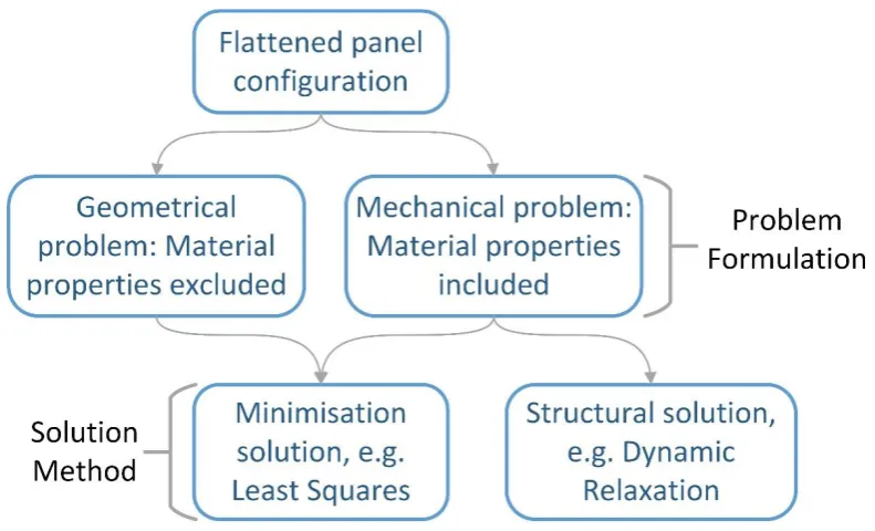
Figure 2.3 - Stress reduction problem formulations, solution methods and the relationship
between them ... 20
Figure 2.4 – Distinct vs integrated methods for stress reduction and compensation ... 21
Figure 2.5 - Illustration of shear deformation resulting from the tensioning of a planar net into
doubly curved geometry – adapted from Wagner [18] ... 28
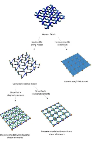
Figure 2.6 - Numerical models and their relation to base fabric ... 33
Figure 3.1 – Proposed discrete element mesh, comprising tensile elements, shear elements, and
nodes ... 44
Figure 3.2 - Deformation of a single tensile element in 3D space ... 45
Figure 3.3 - Area of fabric represented by a given element ... 47
Figure 3.4 – Areas bound by other elements, adjacent to the element for which the width is
being calculated ... 48
Figure 3.5 - Calculation of area by splitting a quadrilateral into four triangles ... 49
Figure 3.6 - Omission of part of the fabric from the material response, if only half of the area is
used to define the width for elements adjacent to non-parallel boundaries ... 49
Figure 3.7 – Relevant areas when calculating width for element A-B ... 50
IX
Figure 3.9 - Shear strain represented as angle change between warp and weft elements ... 54
Figure 3.10 - Shear forces, resolved shear force, and resistance force for shear deformation in Figure 3.9 ... 55
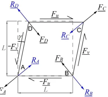
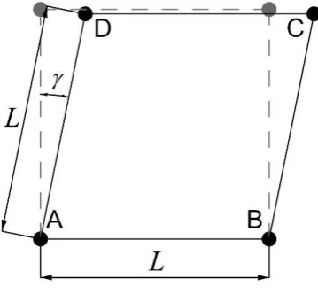
Figure 3.11 - Square of fabric, dimensions L x L, with shear action forces, and corner reactions ... 57
Figure 3.12 - Equivalent representation with proposed discrete elements ... 59
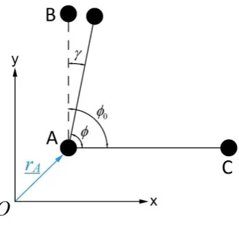
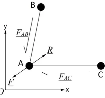
Figure 3.13 - Free body diagram of node A ... 60
Figure 3.14 - Free body diagram of node B ... 62
Figure 3.15 - Free body diagram of node C ... 63
Figure 3.16 - Free body diagram of node D... 64
Figure 3.17 - Trace of kinetic energy around peak... 70
Figure 3.18 - Screenshot of the discrete element model implemented using VB.Net ... 74
Figure 3.19 - Pseudocode describing the set up process for running dynamic relaxation ... 75
Figure 3.20 – Dynamic Relaxation pseudocode ... 76
Figure 3.21 - Dynamic Relaxation pseudocode continued ... 77
Figure 4.1 (a) - Interpolation of a catenoid shape by revolving a radial line of element edges around the centre axis. The original mesh is shown in green. ... 83
Figure 4.1 (b) - Interpolated surface with geodesic seams defined. ... 83
Figure 4.1 (c) - Surface split into individual panels, which can now be flattened... 83
Figure 4.2 - Comparison of different mesh constructions. The red circle indicates the longer elements in mesh (a), not present in mesh (b) ... 85
Figure 4.3 - Meshing a panel by constructing geodesics in two directions ... 86
X
Figure 4.5 - Flattening of a panel by direct projection, showing projection of nodes to the plane
... 88
Figure 4.6 (a) - Definition of the 'spine' of elements on the panel to be flattened ... 89
Figure 4.6 (b) - Unrolling of the spine of elements to the plane ... 90
Figure 4.6 (c) - Unrolling of the elements (including boundary elements) approximately perpendicular to the spine ... 90
Figure 4.6 (d) - Interpolation of the elements (including boundary elements) approximately parallel to the spine, thus completing the unrolling of the mesh ... 91
Figure 4.7 - Construction of a point C on a surface S that is distance L1 from a point A and distance L2 from a point B ... 92
Figure 4.8 (a) - Definition of two spines on the mesh ... 93
Figure 4.8 (b) - Mapping of the spines to the plane ... 94
Figure 4.8 (c) - Mapping of the first line of nodes using the intersection of two circles in the plane ... 94
Figure 4.8 (d) – Mapping of the next line of nodes using the intersection of two circles in the plane ... 95
Figure 4.9 - Typical restraints for a flattened panel. Nodes in red are restrained in the directions indicated by the arrows. All nodes are additionally restrained perpendicular to the plane of the panel ... 97
Figure 4.10 - Intersection of orthogonal lines with defined cutting panel boundary ... 99
Figure 4.11 - Misrepresentation of boundary due to poor choice of orthogonal grid lines ... 100
Figure 4.12 - Portions of triangulated and non-triangulated meshes ... 102
Figure 4.13 - Conditions for joining of panels ... 104
XI
Figure 4.14 (b) - Re-orientation of 3D panel geometry, and subsequent mapping of boundary
nodes (steps 1 & 2) ... 105
Figure 4.14 (c) - Rotation and translation of mapped panel to appropriate location in assembled structure (step 3) ... 106
Figure 4.15 - Multiple panels arranged appropriately, to allow joining of adjacent panels (due to symmetry one quarter of this structure is sufficient for performing analyses) ... 106
Figure 4.16 – Elements along a common edge ... 108
Figure 4.17 – Elements A-B and C-D become element P-Q ... 108
Figure 4.18 - Joined mesh representing portion of structure (due to symmetry one quarter of this structure is sufficient for performing analyses) ... 109
Figure 5.1 – Form-found Catenoid geometry from Linhard et al. [6] ... 115
Figure 5.2 – Axial stresses incurred by direct projection ... 117
Figure 5.3 – Axial stresses incurred through unrolling with one spine ... 118
Figure 5.4 – Axial stresses incurred through unrolling with two spines ... 118
Figure 5.5 - Gaussian curvature across the panel for the geometry from Linhard et al. [6]... 119
Figure 5.6 – Shear stresses incurred through flattening by direct projection ... 121
Figure 5.7 - Shear stresses incurred through unrolling with one spine ... 121
Figure 5.8 – Shear stresses incurred through unrolling with two spines ... 122
Figure 5.9 – Residual stresses after stress reduction and compensation without including the shear stiffness of the fabric, after direct projection flattening ... 124
Figure 5.10 – Residual stresses after stress reduction and compensation without including the shear stiffness of the fabric, after flattening by unrolling with one spine ... 125
XII
Figure 5.12 – Residual stresses after stress reduction and compensation, including the shear
stiffness of the fabric, after direct projection flattening ... 127
Figure 5.13 – Residual stresses after stress reduction and compensation, including the shear
stiffness of the fabric, after flattening by unrolling with one spine ... 127
Figure 5.14 – Residual stresses after stress reduction and compensation, including the shear
stiffness of the fabric, after flattening by unrolling with two spines ... 128
Figure 5.15 – Residual shear stresses after stress reduction and compensation, including the
shear stiffness of the fabric, after flattening by direction projection ... 128
Figure 5.16 – Residual shear stresses after stress reduction and compensation, including the
shear stiffness of the fabric, after flattening by unrolling with a single spine ... 129
Figure 5.17 – Residual shear stresses after stress reduction and compensation, including the
shear stiffness of the fabric, for flattening by unrolling with two spines ... 129
Figure 5.18 - Resultant cutting pattern boundaries for each flattening method, after stress
reduction and compensation is conducted without shear ... 132
Figure 5.19 - Resultant cutting pattern boundaries for each flattening method when stress
reduction and compensation is conducted with shear ... 133
Figure 5.20 - Comparison of cutting patterns resulting from unrolling with one spine, after stress
reduction and compensation is conducted with and without shear ... 134
Figure 5.21 – Residual stresses after stress reduction and compensation, without including the
shear stiffness of the fabric, for the geometry from Moncrieff & Topping [4] ... 137
Figure 5.22 – Residual stresses after stress reduction and compensation, including the shear
stiffness of the fabric, for the geometry from Moncrieff & Topping [4] ... 138
Figure 5.23 – Residual shear stresses after stress reduction and compensation, including the
XIII
Figure 5.24 - Comparison of cutting patterns for the geometry from Moncrieff & Topping [4]
... 139
Figure 5.25 - Plan view of node restraints for the analysis of ¼ of the geometry from Linhard et
al. [6] ... 141
Figure 5.26 - Warp stress deviation after assembly of the cutting patterns for the geometry from
Linhard et al. [6], without including shear in the analysis ... 141
Figure 5.27 - Weft stress deviation after assembly of the cutting patterns for the geometry from
Linhard et al. [6], without including shear in the analysis ... 142
Figure 5.28 – Principal stresses after pattern assembly – reproduced from Linhard et al. [6] 142
Figure 5.29 - Warp stress deviation after assembly of the cutting patterns for the geometry from
Moncrieff & Topping [4], without including shear in the analysis ... 144
Figure 5.30 - Weft stress deviation after assembly of the cutting patterns for the geometry from
Moncrieff & Topping [4], without including shear in the analysis ... 145
Figure 5.31 – Stress deviation after pattern assembly – original results from Moncrieff & Topping
[4] ... 145
Figure 5.32 - Warp stress deviation after assembly of the cutting patterns for the geometry from
Linhard et al. [6], including shear in the analysis ... 148
Figure 5.33 - Weft stress deviation after assembly of the cutting patterns for the geometry from
Linhard et al. [6], including shear in the analysis ... 148
Figure 5.34 – Shear stresses after assembly of the cutting patterns for the geometry from Linhard
et al. [6], including shear in the analysis ... 149
Figure 5.35 - Warp stress deviation after assembly of the cutting patterns for the geometry from
Moncrieff & Topping [4], including shear in the analysis ... 151
Figure 5.36 - Weft stress deviation after assembly of the cutting patterns for the geometry from
XIV
Figure 5.37 – Shear stresses after assembly of the cutting patterns for the geometry from
Moncrieff & Topping [4], including shear in the analysis ... 152
Figure 5.38 - Close up of warp stresses near lower boundary for results shown in Figures 5.35 –
5.37 ... 153
Figure 5.39 - Close up of shear stresses near lower boundary for results shown in Figures 5.35 –
5.37 ... 154
Figure 5.40 – Differing shear triangle sizes around a node and their effect on the forces
apportioned to that node ... 155
Figure 5.41 - Triangulated and non-triangulated mesh configurations for cutting patterns
generated for the geometry from Linhard et al. [6], with shear included in the analysis ... 157
Figure 5.42 - Warp stress deviation after assembly of a non-triangulated mesh, for the geometry
from Linhard et al. [6], including shear in the analysis ... 158
Figure 5.43 - Weft stress deviation after assembly of a non-triangulated mesh at the seam lines,
for the geometry from Linhard et al. [6], including shear in the analysis ... 158
Figure 5.44 - Deviation of the boundary from its expected position, after assembly of a
non-triangulated mesh, for the geometry from Linhard et al. [6], including shear in the analysis . 159
Figure 5.45 – Boundary forces after assembly of the triangulated mesh, for the geometry from
Linhard et al. [6], including shear in the analysis ... 160
Figure 5.46 – Boundary forces after assembly of the non-triangulated mesh, for the geometry
from Linhard et al. [6], including shear in the analysis ... 161
Figure 5.47 – Gross shear deformations after assembly of the non-triangulated mesh, for the
geometry from Linhard et al. [6], including shear in the analysis ... 164
Figure 5.48 – Shear stresses after assembly of the triangulated mesh, for the geometry from
XV
Figure 5.49 - Restriction of node movement due to connectivity of elements, and resulting
control of shear deformations ... 166
Figure 6.1 - 3D form-found panel with two different meshes – (a) current, rectilinear mesh, (b)
XVI List of Tables
Table 1.1 – PVC coated polyester fabric classifications and relevant material properties –
adapted from [12] (originally [13,14])... 8
Table 1.2 - PTFE coated glass fabric classifications and relevant material properties – adapted
from [12] (originally [13,14]) ... 8
XVII Acknowledgements
I would like to express gratitude to a number of people who have made this thesis possible.
I would first and foremost like to thank my supervisor, Professor Wanda J Lewis, for her
enthusiasm, patience and guidance over the last four years.
Secondly I would like to thank Dr Thomas Li and Peter Debney of Arup, whose insights, discussion
and comparison of methods and results strengthened and expanded the direction of this
research.
Furthermore I would like to thank the Rhino Developer community, and Dale Fugier of Robert
McNeel & Associates, whose assistance with troubleshooting program code was most valuable
in completion of this work.
Thanks go to the members of the Civil Research Group at the University of Warwick for their
probing questions, which have strengthened this research.
Further thanks go to the admin staff and members of the IT department at the School of
Engineering, University of Warwick, particularly Kerrie Hatton, for their patience and assistance.
Finally, the greatest thanks of all go to my partner, Leanne Dew, for her encouragement,
XVIII Declaration
This thesis is submitted to the University of Warwick in support of my application for the degree
of Doctor of Philosophy. It has been composed by myself and has not been submitted in any
previous application for any degree.
The work presented was carried out by the author, except where indicated otherwise in the text.
Parts of this thesis have been published by the author, in the following journal and conference
papers:
1. Gale S, Lewis WJ. Patterning of tensile fabric structures with a discrete element model using
dynamic relaxation. Comput Struct 2016;169:112–21.
2. Gale S, Lewis WJ. Computational patterning methods for tensioned fabric structures. Use of
a discrete element model. Proc. Int. Assoc. Shell Spat. Struct. Symp. 2015, Amsterdam,
XIX Abstract
Tensile fabric structures are efficient and cost effective structural systems for covering large
areas. The performance of such structures is highly dependent on their geometry, and for this
reason they must be doubly curved. However, doubly curved surfaces may not be formed from
flat fabric without incurring distortions. The process of patterning is employed to determine the
planar configuration of panels, such that after assembly, these distortions are minimised.
However, patterning is sensitive to the numerical models and processes employed. Shear of the
fabric is required for it to adopt a doubly curved shape, but this has been overlooked in the
numerical models used currently for the patterning of tensile fabric structures.
On this basis, a discrete element model for numerical representation of the fabric, during the
patterning process, is proposed and examined in this thesis. Further to this, the computational
process of patterning is examined thoroughly, and improvements to sub-processes within
patterning form part of a proposed patterning method.
This thesis reviews the literature relating to tensile fabric structures, patterning, and numerical
modelling. The discrete model is described, along with its implementation in the proposed
patterning method. Comparison with published results is included to evaluate the suitability of
the proposed model and patterning method.
It is shown that the proposed discrete element model offers an alternative model for
architectural fabrics at the patterning stage. Conditions for successful use of the model are
stated and explored. In addition to this, the proposed improvements to the patterning process
XX List of Symbols
Symbol Quantity
G
Gaussian curvature1
First principal curvature2
Second principal curvature0
L Element reference length
L Element current length
Element strainA
r
Node A position vector (current configuration)B
r
Node B position vector (current configuration)0
A
r Node A position vector (reference configuration)
0
B
r Node B position vector (reference configuration)
Element tensile stress( / )w f
E Fabric tensile modulus in either the warp or weft direction
( / )
P w f
Prescribed pre-stress in either the warp or weft directionw Fabric width represented by an element
1
A First adjacent area
2
A
Second adjacent areaF
Element tensile forced
Element direction unit vectorXXI
u
F Applied shear force 1
v
F Applied shear force 2
1
F Resolved force 1
2
F Resolved force 2
0
Rest angle between two elements (reference configuration)
Current shear angle between two elementsC
r
Node C Position Vector
Shear stressG Fabric shear modulus
AB
F
Shear force along side ABAC
F
Shear force along side ACBA
v
Vector from node B to node ACA
v
Vector from node C to node Au Arbitrary vector
F Resolved shear force
R Resolved shear reaction force
A
R
Resolved shear reaction force at node AB
R
Resolved shear reaction force at node BC
R
Resolved shear reaction force at node CD
XXII
D
r
Position vector of node DA
F
Resolved shear force at node AAD
F
Force along side ADAB
v
Vector from node A to node BAD
v
Vector from node A to node DB
F
Resolved shear force at node BBA
F
Force along side ABBC
F
Force along side BCBC
v
Vector from node B to CCD
v
Vector from node C to DCB
v
Vector from node C to BC
F
Resolved shear force at node CCB
F
Force along side BCCD
F
Force along side CDDA
v
Vector from node D to ADC
v
Vector from node D to CD
F
Resolved shear force at node DDA
F
Force along side ADDC
XXIII
A
R
continuum
Resolved shear reaction force at node A from continuum model
B
R
continuum
Resolved shear reaction force at node B from continuum model
C
R
continuum
Resolved shear reaction force at node C from continuum model
D
R
continuum
Resolved shear reaction force at node D from continuum model
A
R
discrete
Resolved shear reaction force at node A from discrete model
B
R
discrete
Resolved shear reaction force at node B from discrete model
C
R
discrete
Resolved shear reaction force at node C from discrete model
D
R
discrete
Resolved shear reaction force at node D from discrete modelji
N
Node residual force for node j, direction iji
m
Node mass for node j, direction iji
a
Node acceleration for node j, direction iC Damping factor
ji
v
Node velocity for node j, direction iji
P
Forces applied at node j, in direction iEL
K Element stiffness
Nodal displacementN Node residual force vector
m Node mass (scalar)
a Node acceleration vector
1 2
k
XXIV 1
2
k
v Node velocity vector at iteration k - ½
t
Time interval
k Iteration number
1
k
Nodal displacement at iteration k + 1
k
Nodal displacement at iteration kK
Nodal stiffness for iteration k 1k
X
Nodal position for iteration k + 10
X
Nodal position for iteration 0 (reference configuration)1 2
k
KE Kinetic Energy at iteration k + ½
1 2
k
KE Kinetic Energy at iteration k - ½
t Iteration number
a Quadratic coefficient of
t
2b Quadratic coefficient of t
c Quadratic constant
max
t
Iteration corresponding to maximum KE1
KE
Kinetic Energy at iteration t – 3/22
KE Kinetic Energy at iteration t – ½
3
KE Kinetic Energy at iteration t + ½
Adjustment factor for displacements due to KE peak1
k
corrected
Corrected nodal displacement at iteration k + 1
1
k corrected
XXV
S A given surface
L1 Distance from point A to point C on S
L2 Distance from point B to point C on S
P1 Sphere with radius L1
P2 Sphere with radius L2
C1 Circle with radius L1
XXVI List of Abbreviations
2D Two Dimensional or Two Dimensions
3D Three Dimensional or Three Dimensions
DR Dynamic Relaxation
KE Kinetic Energy
NURBS Non-Uniform Rational B-Spline
PTFE Polytetrafluoroethylene
PVC Polyvinyl Chloride
RO Research Objective
Page 1 1 Introduction
1.1 Introduction to tensile fabric structures
Tensile fabric structures comprise a fabric membrane, tensioned within a boundary comprising
rigid structural elements and/or flexible cables. The tension in the fabric may be introduced
through installation of the fabric in the boundary, or by the additional use of air pressure. Fabric
structures supported by air pressure are referred to as pneumatic tensile fabric structures.
Figure 1.1 shows an example of a tensile fabric structure:
Figure 1.1 – Example of a tensile fabric structure. Santa Fe Opera Cantina, California1
Tensioned fabrics have in-plane stiffness only, thus out-of-plane loads must necessarily result in
large displacements and a consequent change in the surface stress field. This change is then
resisted by tension in flexible cables, in turn transferred to rigid supports, or through
compression and/or bending in supporting rigid beam elements. Large out-of-plane
displacements are the main contributor to geometrically nonlinear behaviour.
1 Source: http://www.fabritecstructures.com/sites/default/files/styles/juicebox_medium/public/
Page 2
To prevent excessive deformation, that is to give sufficient stiffness to the membrane, the
surface curvature should be high [1]. In particular, pneumatic tensile structures should be
synclastic (dome-shaped), and non-pneumatic structures should be anticlastic (saddle-shaped)
(Figure 1.2). Pre-stressing is employed, with the intention of ensuring the fabric remains in
tension under external loads over the life span of the structure.
Figure 1.2 - Surfaces with anticlastic and synclastic curvature
The shape of the membrane surface cannot be defined by the design engineer [2], because fabric
will adopt its own shape within a given boundary under pre-stress. Consequently, fabric
structures require form-finding [2,3], a process, historically conducted using physical models [4],
but now most commonly conducted computationally, that finds the equilibrium geometry of a
structure within a prescribed boundary and for a given stress state. Form-finding is the first
phase in the design process of tensile fabric structures.
Both synclastic and anticlastic shapes are doubly curved – they have non-zero principal
curvature in both directions. Doubly curved surfaces cannot be flattened into the plane without
distorting [5], that is, they are not developable [6], but fabrics are flat in their unstressed state,
prior to the construction of the 3D surface. Architectural fabrics have a typical width of 2-3m [5],
Page 3
Such constraints are imposed by the size of the manufacturing apparatuses, and this leads to
larger structures requiring multiple fabric panels to make up the 3D membrane surface. The
configuration of the panels that are assembled into the final structure affects the membrane
form and stress distribution. The effects of pattern shape on structural performance necessitate
a further process in the design of fabric structures, Patterning, be conducted to define the planar
shape of the panels which form the final surface.
1.1.1 Design process
The design process incorporates the two processes of form-finding and patterning, in addition
to analysis of the structure under load. Historically, in the design process the analyses were
conducted in the following order:
1. Form-finding – finding the 3D shape of the membrane surface under pre-stress
2. Load Analysis – finding the stresses and deflections of the form-found structure, due to
environmental loading such as rain or snow
3. Patterning – determining the shape of the planar panels, which will be cut from the
fabric and assembled to form the final membrane surface
However, given the effect of the cutting pattern on the membrane surface stress field, as
demonstrated through this work, it is advisable to conduct patterning before load analysis. In
this way, the assembled cutting pattern is analysed for performance under load, accommodating
variations in the surface stress field due to the patterning process. Consequently, the design
process should be conducted in the following order:
1. Form-finding
2. Patterning
Page 4
Form-finding and patterning are now discussed briefly. A more detailed discussion of patterning
is presented in chapter 2.
1.2 Form-finding
As mentioned, fabrics sustained by a boundary will adopt their own unique shape in response
to load. In the case of tensile fabric structures, the boundary is defined at the design stage, but
the fabric membrane shape cannot be specified simply.
In the design of structures composed of traditional materials such as steel or concrete, the
engineer specifies the geometry of a structural component and evaluates its maximum stress
capacity. The capacity of the component is compared with the expected stress state to indicate
its suitability. In this manner, the geometry of the structural component is a free choice variable,
and the capacity is a calculated value.
In the process of form-finding, however, the nature of these quantities is reversed, and the
intended stress state is specified. Form-finding is then used to generate the geometry of the
structure - for a certain boundary - that has the prescribed stress state. It then remains only to
specify the correct material to ensure the structure’s capacity to cope with the prescribed stress
and further imposed loads, such as those arising from wind or snow. For tensile fabric structures,
the prescribed stress state is the pre-stress desired in the membrane. (Typical pre-stresses are
specified in section 1.4).
Hence, the exact objective of form-finding is to determine the form of a membrane structure,
with specified boundary conditions and pre-stress, such that that resulting form is in equilibrium
[6] under the prescribed pre-stress. The nature of membrane structures provides the
opportunity to generate efficient structural forms, in particular, those of minimal surfaces.
Where a uniform membrane stress is specified during the form-finding process, the structure
Page 5 1.2.1 Minimal surfaces
Minimal surfaces are defined as surfaces with zero mean curvature at every point [8], and are
well documented in the field of mathematical geometry [9]. Of specific interest, however, is the
property that when considering the area functional of a surface, the extremals correspond to
minimal surfaces [9]. In particular, the minima of the area functional correspond to stable
minimal surfaces – surfaces that minimise their surface area.
Where membrane surfaces adopt the form of a stable minimal surface, they can be considered
to represent optimal structures. The prescription of a uniform stress field during form-finding
results in a structure of minimal area [10] – in this structure, stress concentrations are eliminated
(no portion of the structure is under-utilised), and the quantity of material used to achieve this
is minimal. The physical realisation of these structures is however a challenge, necessitating
careful patterning.
1.3 Patterning
The mathematical condition of non-developability for membrane surfaces necessitates the
process of patterning (see section 2.1.1). Patterning is now conducted using computational
methods, and comprises the following 4-5 steps:
1. Subdivision of the membrane to define the panels which will make up the final
structure. The panels are defined by the position of the seams on the surface. These
seams are present in the final, built structure, and comprise an overlap of fabric
between adjacent panels, which is then sewn or welded [11].
2. Flattening of the resulting panels from 3D to 2D. Flattening incurs distortions on account
of the non-developability of the surface.
3. Stress reduction, applied to the flattened panels, to reduce as much as possible the
Page 6
membrane surface, complete nullification of the stresses induced by flattening is not
possible. Stress reduction methods tend to be iterative.
4. Compensation to reduce the 2D panel in size, to account for pre-stressing. The
membrane surface represents a stressed geometry, and the fabric from which the
planar panels will be cut is not stressed. Because of this, the panels are reduced in size,
such that the act of installing the panels in the boundary of the final, built structure gives
rise to the intended pre-stress. Steps 3 & 4 may be performed in one process [6].
An additional fifth step is included in some, but not all, analyses:
5. Panel assembly to evaluate the cutting pattern, by comparison with the intended stress
state and geometry. Because stress reduction cannot give completely stress-free panels,
residual stresses will be present in the final membrane. Thus, the cutting pattern
determined by steps 1 – 4 may be evaluated by finding the equilibrium geometry of the
assembled panels – stresses after erection are thus calculated.
1.4 Architectural fabrics, types and composition
Architectural fabrics comprise woven fibres with a polymer topcoat (Figure 1.3). The two most
commonly used fabrics are PVC coated polyester, and PTFE coated glass fibre [12,13]. PVC
coated polyester is the more common of the two, and has a lifespan of around 15 years,
compared with PTFE coated glass fibre, which can have a lifespan of 30+ years, though
manufacturers guarantee only 15 years [12]. The fibres in the fabric run in two directions, the
stiffer warp direction, and the weft (or in North America, the fill) direction. The fibres are
approximately orthogonal in planar fabrics, in either a plain weave (as in Figure 1.3) or Panama
bond configuration. Panama bond is similar to that of plain weave, but multiple fibres are
Page 7
Figure 1.3 – Woven fabric structure2
Fabrics come in a variety of weights and strengths, and are classified as such, though no
standardised classifications are available. The classifications for PVC were proposed by the
working group (WG) for architecture at Messe Frankfurt, and a French design guide, as stated in
[13]. PVC coated polyester fabrics are grouped within the classifications Type 1 to Type 5, and
PTFE coated glass fabrics are categorised as Type G1 to G7 [12]. Tables 1.1 and 1.2 show these
classifications, and relevant material properties. It is seen in tables 1.1 and 1.2 that the material
properties relating to stress are given in units of kN/m, not kN/m2. The same applies to elastic
properties (e.g. modulus of elasticity). This is because the small thickness of architectural fabrics
can magnify errors when dividing the force per width by this small thickness [12]. The tensile
strength of the fabric is measured using a strip tensile test, and the tear strength of the fabric
through a trapezoidal test [12].
Page 8
[image:36.595.89.482.121.352.2]Table 1.1 – PVC coated polyester fabric classifications and relevant material properties – adapted from [12] (originally [13,14])
Table 1.2 - PTFE coated glass fabric classifications and relevant material properties – adapted from [12] (originally [13,14])
Typical pre-stresses for the two materials are 0.7 kN/m to 2.0 kN/m for PVC coated polyester
[12,14], and 2.0 kN/m to 5.0 kN/m for PTFE coated glass fibre [14]. Alternatively, the following
heuristics may be used: for PVC coated polyester, the pre-stress should be greater than 1.3% of
the average tensile strip capacity in both directions [14]; for PTFE coated glass fibre, the
pre-stress should be between 2.5% and 6% of the average tensile strip capacity in both directions
[12,14].
Page 9
Architectural fabrics resist external forces through increased tension in the fibres, and shear
stresses in the polymer topcoat. The main load carrying directions of the fabric are defined by
the weave [15], which is approximately orthogonal when the fabric is in an unstressed
configuration. For a flat fabric to adopt a doubly curved shape (required for suitable
performance under load), this weave must shear [15–18], becoming non-orthogonal. The
stiffness properties of architectural fabrics thus change through the assembly of the cutting
patterns, but this phenomenon is not currently accounted for. As will be explored in later
sections, numerical modelling that accounts for this behaviour is required. Further to this, since
the shear stiffness of architectural fabric is low in comparison with the tensile modulus [19], it
is frequently ignored [20].
1.5 Problem statement and scope
Whilst methods for patterning have been developed, the focus of these methods has been to
reduce distortions between the plane and doubly curved shapes, based on orthogonal
mechanical models. That shear of the weave is necessary for the fabric to adopt a doubly curved
shape has been mostly ignored, yet it affects the ultimate accuracy of the generated cutting
patterns. Such shear dependent mechanical behaviour has the greatest impact on membranes
of higher curvature. Thus to analyse and design structures of increasingly complex shape
requires a mechanical model that accommodates this behaviour of architectural fabrics.
Further to this, a thorough examination of patterning, and its individual sub-processes, has not
been previously presented. There remains to be made some improvements to individual
sub-processes, and these are discussed further in chapter 2. Additionally, the inclusion or exclusion
of the shear stiffness throughout patterning merits investigation.
Page 10
In light of the problem stated above (which is further elaborated in chapter 2), the research
presented in this thesis was undertaken to fulfil the following aim and research objectives (ROs):
Aim: The investigation and advancement of the computational process of patterning
RO 1: The development, application and examination of a discrete model
(a) To develop and implement a discrete model for patterning
(b) To examine the model’s suitability for patterning
(c) To identify conditions and guidance for the successful use of discrete models in
patterning
RO 2: The advancement of the computational process of patterning
(a) To develop improved flattening methods and investigate their application
(b) To investigate the effect, on the cutting pattern shape and final stress
distribution, of including shear stiffness throughout patterning
The main contribution of this work is thus the development and application of a discrete element
model for patterning of tensile fabric structures, and the examination of this model. The
proposed model reflects the nature of the fabric weave, and thus accounts for the phenomenon
of weave shear highlighted previously. The development of such a model is timely and relevant
on the basis of sections 1.3 to 1.5 above. It is shown, through comparison with published work,
that the proposed model is simple in application and gives results within the expected range of
stress deviation. Conditions for the successful use of discrete models, elaborated through the
research, are detailed in chapters 5 & 6.
In addition to the development and application of the discrete model, further contributions
were made through the development of geometric flattening methods, aimed at reducing
Page 11
these is discussed in chapter 2, and the developed methods and their application are detailed in
chapters 4 & 5.
1.7 Structure of Thesis
In presenting the research outlined above, this thesis is structured in the following way:
In chapter 2, a review of the literature and key concepts pertaining to the numerical modelling
and patterning of tensile fabric structures is presented. Form-finding, and the consequent
doubly curved surface shapes are briefly discussed as the basis for patterning. Patterning is then
explored in detail, starting with the mathematical basis of patterning, before each phase of the
computational process is examined. Numerical modelling is then explored. The behaviour of
architectural fabrics, and the use of finite element and discrete element models are discussed.
The use of discrete models is advocated, based on the challenges identified, and provides the
basis for the proposed discrete model.
Chapter 3 presents the proposed discrete model, and solution by the dynamic relaxation
method with kinetic damping. The modelling of tensile behaviour is presented, including
methods for overcoming limitations in models proposed by other authors. Modelling of the
shear resistance of the fabric is shown next. A brief review of the dynamic relaxation method is
presented, to illustrate the solution of problems posed for various stages of the proposed
patterning method. The computational implementation of the discrete model within the
dynamic relaxation method is explained, with the inclusion of pseudocode.
Chapter 4 details the proposed patterning method. The method employs the discrete model
together with the solution by the dynamic relaxation method presented in chapter 3. In the first
part of chapter 4, the proposed method for determining the cutting pattern is presented,
including methods for each of the patterning steps identified in chapters 1 & 2. The proposed
re-Page 12
meshing the panel with an orthogonal mesh, and final equilibrium finding by dynamic relaxation
is mentioned.
Chapter 5 presents results from the application of the proposed patterning method using the
discrete element model. Cutting patterns generated using the methods outlined in chapter 4 are
shown for two examples taken from the literature. Comparisons of cutting patterns generated
with different methods, including the one proposed in this thesis, are presented and discussed.
The assembly of the generated cutting patterns is shown, facilitating comparison with published
work. It is shown that the discrete element model gives results within the expected ranges
quoted in literature. Conditions for successful use of the discrete model are presented using the
examples.
Chapter 6 presents the summary and conclusions drawn from the work, including conditions for
successful use of the discrete model, together with reflections on the effectiveness of the
developed patterning method. Suggested further work is then presented.
1.8 Publications arising from the research
This research resulted in two publications:
1. Journal paper: “Patterning of tensile fabric structures with a discrete element model using
dynamic relaxation”, in Computers & Structures 2016 [21].
2. Conference paper: “Computational patterning methods for tensioned fabric structures. Use
Page 13 2 Literature review
This chapter presents in depth explorations of patterning and numerical modelling, and the
literature relating to these topics. The general design process and form-finding were explored
in sufficient detail in chapter 1 and are not explored further. The key points of the review are
presented in the summary of this chapter.
2.1 Patterning
As mentioned, suitable shapes for tensile fabric structures are doubly curved. Such doubly
curved surfaces cannot be formed from planar fabric panels without incurring distortions. The
magnitude and distribution of these distortions, and their consequent stresses across the
membrane surface, are dependent on the method by which the planar panels were determined.
Patterning was historically conducted with the aid of physical models [4]. Now it is mainly
conducted as a computational process. The general computational process comprises a number
of distinct sub-processes. These are discussed below, after a brief review of the mathematical
conditions necessitating patterning.
2.1.1 Mathematical basis of patterning
It is relevant at this point to discuss the necessity of patterning from a mathematical point of
view. One surface may be mapped to another isometrically, that is, in such a way that preserves
all lengths on the surface, if and only if they have identical first fundamental forms [23]. Such a
requirement equates to the two surfaces having equal Gaussian curvature at corresponding
points. Since tensile fabric structures should be doubly curved to resist external loads, they have
non-zero Gaussian curvature (G). Gaussian curvature is defined as the product of the two
principal curvatures at a point on the surface [8]:
1 2 G
Page 14
Where 1 &2are the first and second principal curvatures respectively. For pneumatic tensile
fabric structures, G 0 and for non-pneumatic tensile fabric structures, G 0. Plane
surfaces haveG 0. Positive Gaussian curvature indicates a synclastic surface, negative
Gaussian curvature indicates an anticlastic surface. Zero Gaussian curvature indicates a flat
surface.
Isometric mappings are mappings that preserve all lengths between the original and mapped
geometry, giving rise to no stresses, and are equivalent to the combination of conformal and
equiareal mappings [23]. These mappings are in turn defined thusly: conformal mappings confer
no changes in angles between the original and mapped geometry; equiareal mappings confer
no changes in areas between the original and mapped geometry [23]. In an engineering context,
conformal mappings result in zero shear stress as a result of the mapping.
It is not possible to fully nullify the stresses induced by non-developability – an isometric
mapping is not possible, as explained above. Thus, in defining the cutting pattern for tensile
fabric structures, the mapping between the doubly curved form-found surface, and the plane,
must accommodate a trade-off between shear stresses and tensile stresses.
2.1.2 Computational pattering – the 5-step process
The mathematical condition of non-developability for membrane surfaces necessitates the
process of patterning. Patterning is now conducted using computational methods, and
comprises the following 4-5 steps, as previously mentioned in chapter 1, section 1.3. The 5-step
process is presented in short here:
1. Subdivision of the membrane by defining seams on the form-found surface
2. Flattening of the resulting panels from 3D to 2D
Page 15
4. Compensation to scale the 2D panel to account for pre-stressing
An additional fifth step is included in some, but not all, analyses:
5. Panel assembly to visualise the final 3D form and calculate stresses
Steps 1-4 concern the method of determining the cutting pattern. Step 5 concerns the simulation
of the assembly of the cutting pattern to determine its suitability.
The above five steps are discussed separately, in detail, in the following sections.
2.1.3 Subdivision of the membrane
The form-found shape represents an idealised surface geometry for the given boundary
conditions. This surface must be divided into a series of sub-surfaces representing the panels
from which the structure will be fabricated. This sub-division is achieved by defining the
positions of the seams that will be present in the assembled structure. Seams in the physical
structure are constructed from overlapping, and welding (or less commonly sewing), the edges
of adjacent panels [11].
When defining the positions of the seams on the surface, it is generally accepted that the seams
should follow geodesics [5,15,24]. Geodesics represent the path that a cable adopts when
stretched across the surface with constant stress [25]. Errors, such as wrinkling in the fabric, may
be introduced during the welding of the seams, when fabricating and assembling the membrane.
For this reason, seams should run through the regions of lowest curvature.
The seams dictate the size of the individual panels, and consequently the curvatures across each
panel. The subdivision of the membrane by seams thus affects the subsequent processes of
flattening, stress reduction and compensation, and the suitability of the final cutting pattern.
Page 16
The form-found surface, and its constituent panels after subdivision, are doubly curved. To
produce a pattern suitable for cutting from planar cloth, the planar configuration of the
constituent panels must be found, and the first step is to flatten the 3D panels into the plane.
Historically, so called “cloth unfolding” [26] (Figure 2.1) was employed to flatten the membrane.
Individual panels were represented by a developable polyhedral strip which was unfolded into
the plane [4,20,26] in a procedural manner. The polyhedral representation tended to use only a
single row of elements for each panel, representing a significant misrepresentation of the
original panel geometry, and non-seam panel edges [26]. It has similarly been noted, owing to
this use of a single row of elements, that a triangular polyhedral representation of a panel does
not offer an accurate representation for smaller structures [20]. For two structures of similar
geometry, but different size, where the maximum panel width is the same for both structures,
the smaller structure requires fewer panels. Thus, the panels in the smaller structure represent
surfaces of higher curvature, and the error in the approximation of the surface by a single row
of elements is particularly acute.
Page 17
Cloth unfolding was, in the past, the sole method used to account for the distortions due to
double curvature, when determining the planar cutting patterns. Cloth unfolding was
accompanied only by compensation, to reduce the cutting pattern in size, in light of the
pre-stress. In view of the drawbacks highlighted above, recent methods of patterning employ further
computational methods to reduce the stresses from flattening [20], as discussed in the following
section. An adaptation of cloth unfolding does, however, offer a computationally efficient
method of minimising the stresses due to flattening, before computationally intensive iterative
methods are employed. Use of such a method in the flattening process is often overlooked, and
simple projection of the panel to the plane is used. Methods for flattening, that minimise
distortions through simple geometrical algorithms, are presented in chapter 4.
2.1.5 Stress reduction
Flattening, whether using cloth unfolding or not, results in distorted patterns. Distortions in the
pattern must be reduced. The problem of reducing distortions in the mapping of a doubly curved
surface to a planar surface is a mathematical one, having been explored in a number of other
fields, including cartography [23]. The equivalent engineering problem is formulated by
considering the reduction of the stresses that these distortions incur.
The reduction of stresses in the determination of the cutting pattern is approached both as a
mathematical problem and an engineering one. In this thesis, formulation of the problem as a
reduction of the distortions is termed the geometrical problem formulation, and formulation of
the problem as a stress reduction problem is termed the mechanical problem formulation. These
two problem formulations are in essence separated by the exclusion or inclusion of the material
properties. It has been mentioned in [27] that excluding material properties results in a purely
Page 18
A number of solutions to these problem formulations have been proposed, and these solutions
can be further categorised. Two main solution methods are used; the more common, termed
the ‘minimisation solution’, formulates the reduction of the distortions, or stresses, as an
optimisation problem. In the case of the geometrical problem formulation, the description of
the distortions constitutes an objective function. In the case of the mechanical problem
formulation, the description of the stresses, or the deviation of the stresses from the intended
design pre-stress, constitute an objective function. Solution by the minimisation solution has
been achieved by methods such as least squares, applied to geometrical [28], and mechanical
[3,26] problem formulations.
The second solution is termed the ‘structural solution’. The distorted, flattened geometry
represents a configuration of the subsurface which is not in equilibrium, in the absence of
sufficient restraints. With careful selection of the restraints, the panel can be equilibrated using
a solution method, such as dynamic relaxation [5] or Newton-Raphson [6]. This equilibration
process has the effect of releasing the stresses, and yields a subsurface geometry with reduced
Page 19
Figure 2.2 - Reduction of stresses using the structural solution - adapted from Linhard et al. [6]
In Figure 2.2 (a), the 3D surface is flattened into the plane. The method of flattening incurs
distortions, such that under relaxation (Figure 2.2 (b)), the left hand pinned support remains
stationary, and the right hand roller support, and other nodes on the 2D surface, move in plane.
This movement is what permits the release of the stresses, providing sufficient restraints are
employed to prevent rigid body transformations.
Because the structural solution models a physical process, material properties are required.
Thus, the structural solution is applicable only to the mechanical problem formulation. Figure
Page 20
Figure 2.3 - Stress reduction problem formulations, solution methods and the relationship between them
2.1.6 Compensating for pre-stress
Following the flattening of the panel, and reduction of the stresses induced by this flattening,
the planar panel geometry must be further altered to account for the intended pre-stress in the
assembled membrane shape.
The 3D membrane geometry generated by form-finding represents a configuration of the
surface that is in equilibrium under its own pre-stress. Since the fabric from which the panels
will be cut is unstressed in its planar form, the pre-stress must be accounted for in the generation
of the cutting pattern. In particular, the planar panel must have smaller width and length, and
consequently area, than the form-found panel [18]. This process is known as compensation, and
can be achieved by simple scaling of the panel, or by the application of the same structural
solution methods [5] described in the previous section, with a prescribed pre-stress. At this point
Page 21
It is possible to integrate the processes of stress reduction and compensation, and conduct them
as one process [6]. The comparative benefit of conducting the two processes as one, or
distinctly, is an issue of contention. In [28] it is stated that it is preferable to conduct the
processes separately, whereas in [5,6] the processes are conducted simultaneously. Owing to
the necessity for material parameters during compensation, integrated stress reduction and
compensation is achievable only when using the mechanical problem formulation, though the
method of the solution does not affect the possibility of integration. Figure 2.4 highlights the
difference between integrated and distinct methods.
Figure 2.4 – Distinct vs integrated methods for stress reduction and compensation
2.1.7 Assembly of cutting patterns
Flattening, stress reduction, and compensation wholly define the cutting pattern, providing
sufficient data for the manufacture of the membrane from planar fabric. To evaluate the
suitability of the cutting pattern, patterning processes can include modelling of the assembly of
the cutting pattern [4]. The aim in such a process is not to model the physical construction
process, but rather to see how the combination of panels, which are generated independently
by the flattening, stress reduction, and compensation processes, behave together. Additional
Page 22
stiffness of the surface is increased, and has, in terms of mechanical behaviour, the effect of
acting like a stiff cable in the surface.
Owing to the mathematical considerations presented in section 2.1.1, the stress reduction
process cannot completely nullify the stresses due to non-developability. Thus, it is expected
that the stresses in the surface following pattern assembly will resemble the combination of the
intended pre-stress, and the residual stresses resulting from the stress reduction procedure. It
is not, however, sufficient to say that the stress deviation will simply be the reverse of the
residual stresses – how the panels behave as an assembly cannot be defined without further
analyses.
2.1.8 Integrated approaches, optimisation and genetic algorithms
Given the consideration outlined above, that the assembled structure cannot adopt exactly the
stress distribution dictated during form-finding, and there will be residual stresses, some
methods employ multiple adjustments of the planar pattern [3,6,26,29,30]. These methods
repeatedly conduct flattening, stress reduction and compensation, using the resultant assembly
from the previous iteration to inform the current iteration of these processes.
Adjustments are made based on the residual stresses in the assembled form. The method
presented in [29] employed manual adjustment of the pattern, adding or removing material in
areas of higher or lower stress respectively. In [26] the stress difference between the assembly
of the cutting pattern for the previous iteration and the design stress was used to adjust the
cutting pattern for the current iteration. In [3,6] the patterns were similarly adjusted by
comparison with the assembled shape of the previous pattern in the iteration, through the
formulation of the mechanical process is different. In [30] genetic algorithms were used to
optimise the cutting patterns.

![Table 1.2 - PTFE coated glass fabric classifications and relevant material properties – adapted from [12] (originally [13,14])](https://thumb-us.123doks.com/thumbv2/123dok_us/9491842.455095/36.595.89.482.121.352/table-coated-classifications-relevant-material-properties-adapted-originally.webp)

![Figure 2.5 - Illustration of shear deformation resulting from the tensioning of a planar net into doubly curved geometry – adapted from Wagner [18]](https://thumb-us.123doks.com/thumbv2/123dok_us/9491842.455095/56.595.215.382.85.218/figure-illustration-deformation-resulting-tensioning-geometry-adapted-wagner.webp)