46
©IJRASET: All Rights are Reserved
Comparative Analysis of Resilient Grid Coupling
by Analytical Design
Prof. Nitinchandra R Patel1, Manthan Paskanthi 2, Indravadan Makwana3, Priyansh Hotchandani4, Savan Vasava5
1
Assistant Professor, 2, 3, 4, 5Undergraduate Student, Department of Mechanical Engineering, G H Patel College of Engineering & Technology, Vallabh Vidhyanagar, Gujarat
Abstract: Resilient Coupling comprises mainly two hubs, grid spring and cover to protect the spring to fly off to centrifugal force and to prevent grease to come out. Grid Spring element is so designed that it provides resiliency for variable flexibility of a coupling and damping properties making the coupling very for drives involving high shock loads to the extent of 80%. Unlike gear and disc coupling, resilient coupling have unique ability to reduce vibration by as much as 30%. Misalignment – Angular, Parallel or Axial, that inevitably occurs between rotating shafts, which are independently supported, is also taken care of by the spring element within allowable limits. The grid is torsionally flexible. The circumferential flexibility is progressive due to the curved profile of the grooves – state of the art in resilient coupling design. The grid spring element absorbs impact energy by spreading it over time and thus reduces the magnitude of the peak loads.
Keywords: Torsional shear stress, stiffness, deflection, resultant stress
I. INTRODUCTION
Resilient Grid Coupling is composed of two shaft hubs, a metallic grid spring, and a split cover kit. Torque is transmitted between
the two coupling shaft hubs through the metallic grid spring element. Grid coupling are a popular coupling option where both high torque levels and damping requirements exist. Grid couplings have a unique ability to reduce vibration by as much as 30%, and cushions shock loads to safeguard driving and driven power transmission equipment. They are easy to install and simple to maintain [8]. The grid spring element absorbs impact energy by spreading it out over time, and thus reduces the magnitude of the peak loads. This is possible because of the progressive contact that occurs between the curved profile of the hub teeth and the flexible grid. As the load increases, more of the tooth comes into contact with the flexible grid spring element.
Fig.1 Resilient coupling
A. Problem Arises In Coupling
47
©IJRASET: All Rights are Reserved
B. Remedies To Eliminate The Problem
We must do maintenance at regular intervals. Try not to use parallel shaft misalignment and only designed to handle about a half a degree of angular misalignment. Do daily lubrication so wear and tear gets low.
II. ANACQUAINTANCEWITHTHERESILIENTCOUPLING
A coupling is a device used to connect two shafts together at their ends for the purpose of transmitting power.[1,2] The primary purpose of couplings is to join two pieces of rotating equipment while permitting some degree of misalignment or end movement or both. In a more general context, a coupling can also be a mechanical device that serves to connect the ends of adjacent parts or objects. Couplings do not normally allow disconnection of shafts during operation, however there are torque limiting couplings which can slip or disconnect when some torque limit is exceeded. Selection, installation and maintenance of couplings can lead to reduced maintenance time and maintenance cost.
Fig.2 Shaft Coupling
Shaft couplings are used in machinery for several purposes. A primary function is to transfer the power from one end to another end. For example a motor transfers power to pump through coupling. Like other common uses are:
1) To alter the vibration characteristics of rotating units.
2) To connect driving and the driven parts.
3) To introduce protection against the overloads.
4) To provide for the connection of shafts of units that are manufactured separately (such as a motor and generator) and to provide
for disconnection for repairs or alterations.
5) To provide for misalignment of the shafts.
6) To introduce mechanical flexibility.
7) To reduce the transmission of shock loads from one shaft to another shaft.
The couplings are two types – Rigid and flexible. Rigid coupling does not allowed any linear or angular misalignment. It requires rigid connection on coaxial shaft. The said demerits are overcome by flexible couplings. Generally, flexible couplings are allowed linear and angular misalignment.
48
©IJRASET: All Rights are Reserved
III. DESIGNMETHODOLOGY A. Design of Shaft
Shafts are designed on the basis of torsional shear stress induced because of the torque to be transmitted. Shear stress induced in shaft for transmitting torque [4] is given by,
T = (π / 16) * τ * d3
τ = =
where, T = torque, N mm d = shaft diameter, mm
τ = shear stress, MPa
Fig.3 Shaft
B. Design of Hub
A hub is designed considering it as a hollow shaft; with inner diameter equal to diameter of shafts and outer diameter double of that. It is checked for torsional shear stress.
D = 2d
D = Diameter of Hub
Checking under torsional shear stress
τ =
τ≤τall
tf = 0.5 d
L = 1.5 d D1 = 3.5 d
where, tf = thickness of flange, mm
D1 = Outside diameter of flange, mm
L = length of hub, mm
C. Design of spring
A Spring is subjected to pulling load so tensile stress is induced on cross-section of spring [6].
σt = = =
(by taking rectangular cross section area A = b * t)
where, R1 = Radius of flange outer, mm
b = width of cross-section of spring, mm t = thickness, mm
Fig.4 Grid Spring -Direct stress on cross-section of spring due to twisting of spring is:
σd = =
Also, bending stress due to induced bending moment is:
σb = =
σb =
where, I = Moment of inertia, mm4
49
©IJRASET: All Rights are Reserved
The spring is subjected to load in such a way that more than one stresses are induced so by taking combined stresses [7], Combined stress σr= σd + σb
σr = ±
Other parameters are:
-Length of spring: Ls = π D1
-Spring index: C =
-Stiffness (K) =
-Deflection (δ) =
Similarly, by selecting different cross section area for spring component the said design parameters are determined. The standard cross sections are (1) Rectangle (2) Square (3) Elliptical (4) Circle
D. Flowchart for Design of Grid Spring
50
©IJRASET: All Rights are Reserved
E. Programming in MATLAB% Design Of Resilient Grid coupling
P = 50; N = 1600; D = 184; c = 0.8; d = D/2; D1 = 1.5*D; R1 = D1/2; b = 15; t = 5; e = 0.8; b1 = 5; d1 = 5; x = 2.5; y = 7.5; E = 200000; disp ('Torque in N*mm')
T = ((P*60000*1000)/(2*3.1415*N)) disp(sprintf('%10.2f',T))
disp ('Design Of shaft subjected to torsoinal stress in N/mm^2') S = ((16*T)/(3.14*d^3))
disp ('Design Of Hub subjected to torsoinal stress in N/mm^2') S1 = ((16*T)/(3.14*D^3))
disp ('Cross section: Rectangle')
disp ('Design Of Spring subjected To tensile stress in N/mm^2') ST = ((T)/(R1*b*t))
disp ('Design Of Spring subjected To bending stress in N/mm^2') SB = ((T*e*6)/(R1*t^2*b))
disp ('Resultant stress in N/mm^2') Sr = ST+SB
disp ('Stiffness of spring in N/mm') K1 = ((E*b*t)/(3.1415*D1)) disp ('Deflection of spring in mm') X1 = ((T)/(R1*K1))
disp ('Cross section: Elliptical')
disp ('Design Of Spring subjected To tensile stress in N/mm^2') STb =((T)/(R1*3.1415*x*y))
disp ('Design Of Spring subjected To bending stress in N/mm^2') SBb =((T*e*2)/(R1*3.1415*y*x^2))
disp ('Resultant stress in N/mm^2') SRb = STb+SBb
disp ('Stiffness of spring in N/mm') K2 = ((E*3.1415*x*y)/(3.1415*D1)) disp ('Deflection of spring in mm') X2 = ((T)/(R1*K2))
disp ('Cross section: Square')
disp ('Square Spring Subjected to Tensile Stress in N/mm^2') St = ((T)/(R1*b1^2))
disp ('Square Spring Subjected to Bending Stress in N/mm^2') Sb = ((T*e*6)/(R1*b1^3))
disp ('Resultant stress of Square cross section in N/mm^2') SR = St+Sb
disp ('Stiffness of spring in N/mm') K3 = ((E*b1^2)/(3.1415*D1)) disp ('Deflection of spring in mm') X3 = ((T)/(R1*K3))
disp ('Cross section: Circular')
disp (' Circular Spring Subjected To Tensile Stress in N/mm^2') STe = ((T*4)/(R1*3.1415*d1^2))
51
©IJRASET: All Rights are Reserved
disp ('Resultant Stress for circular spring in N/mm^2') Sre = (STe+Sbe)
disp ('Stiffness of spring in N/mm') K4 = ((E*3.1415*d1^2)/(3.1415*D1*4)) disp ('Deflection of spring in mm') X4 = ((T)/(R1*K4))
IV. RESULTSANDDISCUSSION
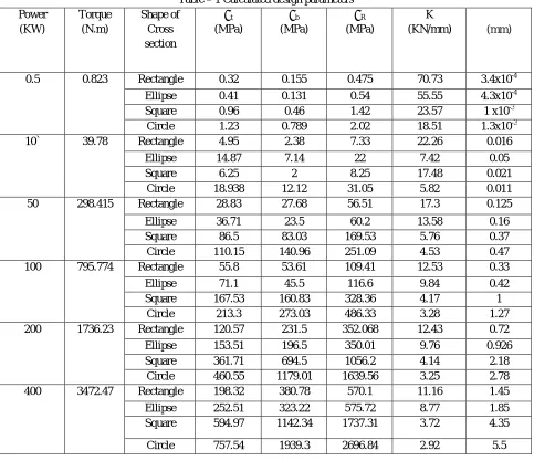
[image:6.612.66.549.250.667.2]In the recent design, the range of power is taken from 0.5 to 400 KW with step of values within this range. At a definite value of torque, the possible cross sections are selected to do stress analysis. Induced stresses in a spring are tensile and bending due applied torsional load on coupling. However, combined stresses are calculated to get resultant value. The spring stiffness and deflection are also calculated to design other parameters.
Table – 1 Calculated design parameters Power (KW) Torque (N.m) Shape of Cross section σt (MPa) σb (MPa) σR (MPa) K
(KN/mm) (mm)
0.5 0.823 Rectangle 0.32 0.155 0.475 70.73 3.4x10⁻⁴
Ellipse 0.41 0.131 0.54 55.55 4.3x10⁻⁴
Square 0.96 0.46 1.42 23.57 1 x10⁻³
Circle 1.23 0.789 2.02 18.51 1.3x10⁻³
10` 39.78 Rectangle 4.95 2.38 7.33 22.26 0.016
Ellipse 14.87 7.14 22 7.42 0.05
Square 6.25 2 8.25 17.48 0.021
Circle 18.938 12.12 31.05 5.82 0.011
50 298.415 Rectangle 28.83 27.68 56.51 17.3 0.125
Ellipse 36.71 23.5 60.2 13.58 0.16
Square 86.5 83.03 169.53 5.76 0.37
Circle 110.15 140.96 251.09 4.53 0.47
100 795.774 Rectangle 55.8 53.61 109.41 12.53 0.33
Ellipse 71.1 45.5 116.6 9.84 0.42
Square 167.53 160.83 328.36 4.17 1
Circle 213.3 273.03 486.33 3.28 1.27
200 1736.23 Rectangle 120.57 231.5 352.068 12.43 0.72
Ellipse 153.51 196.5 350.01 9.76 0.926
Square 361.71 694.5 1056.2 4.14 2.18
Circle 460.55 1179.01 1639.56 3.25 2.78
400 3472.47 Rectangle 198.32 380.78 570.1 11.16 1.45
Ellipse 252.51 323.22 575.72 8.77 1.85
Square 594.97 1142.34 1737.31 3.72 4.35
Circle 757.54 1939.3 2696.84 2.92 5.5
The above table shows the relation between different parameters of spring and power transmitted through it. It is clearly seen that the resultant stress value of the rectangle cross section is the least among the other cross sections which is making it the best cross section for the spring.
52
©IJRASET: All Rights are Reserved
A. Rectangular cross-sectionFig.6 Power vs Resultant stress Fig.7 Power vs Stiffness
Fig. 8 Power vs Deflection
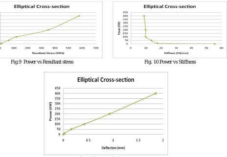
[image:7.612.45.572.56.716.2]B. Elliptical cross-section
[image:7.612.89.554.401.722.2]Fig.9 Power vs Resultant stress Fig. 10 Power vs Stiffness
53
©IJRASET: All Rights are Reserved
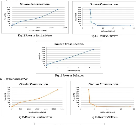
C. Square cross-sectionFig.12 Power vs Resultant stress Fig.13 Power vs Stiffness
Fig.14 Power vs Deflection
[image:8.612.41.560.86.560.2]D. Circular cross-section
Fig.15 Power vs Resultant stress Fig.16 Power vs Stiffness
Fig. 17 Power vs Deflection
54
©IJRASET: All Rights are Reserved
V. CONCLUSION
From above data we can conclude that in rectangular cross-section spring we have minimum stress value. Taking the value for 400 KW power, rectangle has stress value of 570.1 MPa. As comparing it with the different cross sections circular cross section is the one with the highest stress value of 2696.84 MPa. We have also compared the stiffness value and the deflection of the spring for different cross sections. The Stiffness value is reducing as the power transmission increases. The Stiffness in rectangle holds good value as compared to other cross section. Rectangular has 11.16 KN/mm and circular has 2.92 KN/mm for 400 KW. Same way for deflection the as the power increases the deflection increases. The cross section of rectangle has the least deflection as compared to other cross sections. The value of rectangle cross section is 1.45 mm and the circular cross section has the value of 5.5 mm for the 400 KW. Also square and elliptical has intermediate values of the stiffness and deflection. So making rectangular cross section is the most compatible design for the spring.
REFERENCES
[1] R.S.KHURMI and J.K.GUPTA, “Machine Design”, S.CHAND & COMPANY PVT. LTD. 7361 Ram Nagar, New Delhi, 2013. [2] S.G.KULKARNI, “Machine Design”, Tata McGraw-Hill Publishing Company Ltd. 7 West Patel Nagar, New Delhi, 2009.
[3] PSG college of technology, “Design Data”, Kalaikathir Achcagam, Kalaikathir Buildings 963, Avanashi Road Coimbatore, Tamilnadu, 2011.
[4] GITIN M MAITRA & L V PRASAD, “Handbook of Mechanical Design”, Tata McGraw-Hill Publishing Company Ltd. 7 West Patel Nagar, New Delhi, 2010. [5] P H JOSHI,” Machine Tools Handbook Design and Operation”, Tata McGraw-Hill Publishing Company Ltd. 7 West Patel Nagar, New Delhi, 2010.
[6] C.S.SHARMA & KAMLESH PUROHIT, “Design of machine elements”, PHI Learing Limited, M-97 Connaught Circus, New Delhi, 2010
[7] HALL, HOLOWENKO and LAUGHLIN, “Theory and problems of Machine”, Tata McGraw-Hill Publishing Company Ltd. 7 West Patel Nagar, New Delhi, 2009.
[8] Ramees Rahmana A, Dr S Sankar, Dr K S Senthil Kumar, “Replacement of grid coupling with bush pin coupling in blower”, in International journal of innovative research in science engineering and technology, vol 6, Issue 5, May 2017.
[9] Catalogue Lovejoy coupling and universal joints, 2655 Wisconsin Avenue Downer Grove, IL.
[10] Catalogue Flexocon Engineers Pvt. Ltd.,14, Mig Housing Estate, Abakash Apartment, Flat-1c, 1st Floor, Sodepur, Sodepur, Kolkata, West Bengal
AUTHORS’ BIOGRAPHY
Prof. Nitinchandra R. Patel is an Assistant Professor in Mechanical Engineering Department of G. H. Patel College of Engineering & Technology, Vallabh Vidyanagar, Gujarat, India. He did Master degree in Machine Design in 2004 from Sardar Patel University, Vallabh Vidyanagar and Bachelor degree in Mechanical Engineering in 1997 from B.V.M Engineering College, Sardar Patel University. He has more than 22 years’ experience including teaching and industries. He has presented 2 technical research papers in International conferences & published 1 technical research paper in National journal and 24 research papers in International journals. He reviewed a book published by Tata McGraw Hill. He is a Member of Institute of Engineers (I) and Life member of ISTE. He is a reviewer / member in Editorial board of various Peer-reviewed journals. He is also recognized as a Chartered Engineer by Institute of Engineers (I) in Mechanical Engineering Division in 2012.
Manthan C. Paskanthi is a final year undergraduate student at Department of Mechanical Engineering, G H Patel College of Engineering & Technology, Vallabh Vidhyanagar, Gujarat, India
Indravadan B. Makwana is a final year undergraduate student at Department of Mechanical Engineering, G H Patel College of Engineering & Technology, Vallabh Vidhyanagar, Gujarat, India
Priyansh K. Hotchandani is a final year undergraduate student at Department of Mechanical Engineering, G H Patel College of Engineering & Technology, Vallabh Vidhyanagar, Gujarat, India