Interoperability for the design and construction
industry through semantic web technology
Pieter Pauwels1
, Ronald De Meyer1
, and Jan Van Campenhout2
1
Ghent University - Department of Architecture and Urban Planning, J. Plateaustraat 22, 9000 Ghent, Belgium
2
Ghent University - Department of Electronics and Information Systems, Sint-Pietersnieuwstraat 41, 9000 Ghent, Belgium
Abstract. The domain of architecture, engineering and construction
(AEC) has experienced significant improvements with the advent of building information modelling (BIM) applications, which allow AEC specialists to model all information concerning a building design into one three-dimensional building model. Much of these improvements are how-ever generated by the mere availability of such an environment, whereas many more improvements were expected by achieving an appropriate interoperability of information. We are investigating why such an in-teroperability is not reached fully and consider the semantic web as an alternative approach to reach the targeted interoperability. In this pa-per, an AEC description framework based on semantic web technology is presented and compared to the BIM approach, after which we indi-cate how it might solve the issue of interoperability more appropriately. Our evaluation of this investigation indicates the semantic web approach as a valid alternative approach, although considerably more research is needed to show it capable of providing the targeted interoperability of information in the AEC domain.
1
Introduction
The amount and diversity of information is one of the most notable character-istics of a project in the domain of architecture, engineering and construction (AEC). Many domain experts with different backgrounds typically meet within the context of a building project, each of them composing an understanding of the building design and providing a contribution to the project. Each of these experts relies on different software tools for computer-aided design (CAD). Ubiq-uitous to this context of continuous information flows between experts and their CAD tools, is the point where all these information flows come together. Because this point combines several interpretations of the same subject, it is crucial to maintain a correct understanding and control over these interpretations, so as a sufficiently high level of efficiency can be obtained throughout the design and construction process. Since several years, this point is increasingly addressed by diverse building information modelling (BIM) applications [1]. Within a BIM application, an AEC expert is able to model a three-dimensional BIM model
containing all kinds of information about the building designed, including 3D geometry, cost information, material information, etc. In this approach, only one building model is kept at the centre of the AEC design and construction process. Every application should then rely on this central building model so as to achieve interoperability of information throughout the design and construc-tion process within the building design team. By enhancing the communicaconstruc-tion of information between the software tools deployed by AEC specialists, BIM thus improves the information management process in general.
Recent research [2], however, seems to indicate that BIM merely improves this communication process by supplying the means to construct one three-dimensional information model of the building, and considerably less by enhanc-ing the interoperability of this information between the applications deployed by AEC specialists. BIM is namely mainly used for visualisation, clash detection, building design and the construction of an as-built model and less for communi-cation of information to applicommuni-cations for building analyses and calculations [2]. Such an interoperability is, however, one of the main objectives of the Industry Foundation Classes (IFC), a schema designed and built by the International Al-liance for Interoperability (IAI) for the communication of building information between BIM applications [3]. By converting a BIM model to an IFC descrip-tion in one BIM environment, interoperability should be achieved with any other BIM environment and several of the compatible calculation and simulation ap-plications. However, many problems persist in re-using this IFC building infor-mation because it is distorted and/or lost during conversions to and from the IFC schema [4]. This is confirmed by the significant limitations and difficulties we encountered in implementing an energy and acoustic performance checker based on building information in IFC [5]. Although many attribute this problem to a poor implementation practice, we argue in this paper that the root of this poor implementation practice lies in the nature itself of converting semantically rich information. When converting information from one description or repre-sentation into another, information distortion or loss almost always occurs, as this is inherently part of the semantic and syntactic difference between these two description schemas.
Because semantic web technology enables the description of information to-gether with its inherent semantics [6], we are currently investigating the adoption of semantic web technology for improving interoperability in the AEC domain as an alternative to the existing BIM plus IFC approach. Instead of relying on a central IFC standard to enhance interoperability, we suggest finding a way to connect diverse alternative schemas together, among which the IFC schema, but also the schema underlying any of the BIM environments, so that one can describe information as he or she wants and still connect it to representations in other schemas. We thus aim at investigating to what extent several alterna-tive descriptions of one and the same building may coexist and be interrelated in one and the same semantic web, presuming that such an interrelated combi-nation of parallel building descriptions might encompass the issues concerning interoperability through IFC.
We start from a general comparison between BIM and IFC technology, and semantic web technology, after which we investigate to what extent semantic web technology may form a valid alternative for the BIM and IFC approach. This investigation is done in the light of our architectural information modelling (AIM) framework, a framework under development for the enhancement of de-sign and building support based on semantic web technology [7]. In this context, we are building a semantic web graph containing all kinds of building informa-tion, including geometric informainforma-tion, material informainforma-tion, architectural design intents, etc., after which we investigate how applications may retrieve and mean-ingfully reuse this information for the various purposes given above. After this discussion of the current AIM framework, we will discuss how parallel building descriptions may be made available using semantic web technology, as an answer to the interoperability issues outlined above.
2
BIM and the semantic web
2.1 Limitations in the BIM approach
The AEC domain involves all kinds of information, covering material characteris-tics, elementary architectural design notions, legal regulations, three-dimensional parameters, etc. Traditional information systems do not incorporate all this in-formation. At best, an information system incorporates only part of the informa-tion needed and provides support based on this informainforma-tion solely. Consequently, numerous applications have emerged focusing on the calculation of building per-formances, on the checking of the conformance with legal regulations and stan-dards, on the graphic representation and rendering of the design, etc. Because the design and construction process requires the combined input of all this informa-tion, AEC specialists are required to deploy a whole range of diverse applications, going from three-dimensional rendering platforms, to CAD applications for sta-bility or energy performance calculations, to internet platforms with disparate resources and additional documentation, etc. Since each of these applications has its own way of describing and managing building information, considerable amounts of information are remodelled and redescribed according to the schema deployed by the targeted information system. The resulting duplicate 3D infor-mation models inevitably lead to a significant loss of time and resources and to an increased risk of construction errors and misconceptions in the design [8].
Several approaches have been proposed to tackle this situation, the BIM ap-proach being one of the most notable and successful [1]. Within a BIM platform, a designer is able to model a three-dimensional BIM model containing all kinds of information about the building design, including 3D geometry, cost information, material information, etc. Within the same BIM platform, several applications are available that re-use this information and thereby supply a significant set of calculation and simulation modules. In [2], a high percentage of the respondents confirms the expected benefits of BIM, namely a decrease in building cost and an increase in efficiency, especially for the construction-related phases. Because BIM is, however, mainly used for visualisation, clash detection, building design
and the construction of an as-built model [2], these benefits seem not gener-ated by the increased level of interoperability of information, but merely by the availability of an environment to manage building information in one central 3D model as opposed to a collection of 2D CAD drawings. The user remains confined to the schema adopted and thus imposed by the platform developers. It is therefore impossible to describe information that falls out of the original schema, neither is it possible to re-use the information in applications that de-ploy even a slightly different schema, which both occurs often in the case of the AEC domain.
The development and increasing adoption of the Industry Foundation Classes (IFC) encompasses the latter limitation to a certain extent by providing one neu-tral schema to describe building information [3]. It was designed and built as a separate EXPRESS schema [9] within STEP [10] by BuildingSMART, formerly known as the International Alliance for Interoperability (IAI) [11]. Its aim is to provide easy communication of construction-related information back and forth between BIM modelling environments and other IFC-compatible software envi-ronments. Notwithstanding the significant benefits found in the adoption of IFC [2], most of the expected benefits are not met in real world practice. In several use-cases, information communicated through IFC is found to be distorted or lost, consequently making it far from reusable [4, 5]. The conversion process from and to any file format is namely always subject to varying interpretations. In most cases no exact mappings exist between the IFC description of a building and the data schema of the application at hand, making it nearly impossible to achieve the interoperability goal originally targeted. As a result, partners in building projects tend to exchange the IFC model as just another information model, resulting again in multiple building models managed in parallel, contain-ing different information about the same subject.
2.2 Possible enhancements through a semantic web approach Because semantic web technology promises the means to connect all kinds of in-formation into one semantic web, including their inherent semantics [6], it might provide for an appropriate alternative approach. It might namely enable the de-scription of information in several distinct, but nonetheless connected graphs, for instance explicitly connecting a building representation in the IFC schema to representations of the same building according to alternative 3D description schemas, such as the X3D [12] or the STL schema [13]. Applications may rely on this web of information as a central information source to provide services as needed for each of the members of a design team. Several existing approaches have already shown how such usage of semantic web technology may also en-hance decision support in AEC. The conformance-checking system discussed in [14], for instance, shows how semantic queries may be used to check if a building is conform legal regulations. In [15], an IFCOWL system has been developed to enable the translation of the formal IFC schema into a semantic web graph, thereby enabling an improved partitioning of the information described in IFC [15]. We have extended these initial research efforts with an investigation on the
applicability of semantic web technologies in general for building performance checking, more specifically for building acoustics [16], and for the exchange of 3D information within the AEC domain [17]. This research does not focus on the deployment of graphs and ontologies to represent AEC information and improve interoperability, but, instead, elaborates mainly on the usage of rules on top of such graphs for building performance checking and for the conversion of 3D in-formation respectively. The combined merit of having an improved description of the architectural and building information has been discussed in [18] through the presentation of a “graph-based knowledge specification” as a basis for a concep-tual design system named ConDes. Although the presented system is not based on semantic web technology, it gives a good indication of how architectural and building knowledge may be described semantically and how this knowledge may be reused in advanced reasoning processes for an improved design decision sup-port.
3
A web of architectural information
We created a semantic web of architectural information to simulate how archi-tectural information might be available in a semantic web approach. Several initial test cases illustrate how this web of information might be consumed in the targeted AIM framework, thereby illustrating the applicability of semantic web technology for the AEC domain. This will be documented in the remain-der of this paper, thereby leaving out an in-depth discussion of semantic web technologies, as elaborate sources are available elsewhere [19–25].
3.1 AIM facts
The created semantic web contains information described according to both the IFC ontology and to a newly created AIM schema. Both schemas are to be considered complementary since the IFC ontology focuses on describing a building from the perspective of construction and engineering, while the AIM schema aims at more architectural design concepts, such as style information, history information, design intent information, etc. We started with converting the original IFC schema [3] into an OWL ontology [22], thereby largely following the approach presented in [15]. Using this ontology, an online web service is built and maintained [26] through which file-based IFC models can be uploaded for conversion into IFC/RDF graphs [20]. The converted graphs are made available online through a SPARQL endpoint [25] for query access [27].
As a second part of the AIM graph, several AIM ontologies have been built to enable the structured description of architectural content. These ontologies are constructed solely for investigating the applicability of semantic web technology within the AEC field and can by no means be considered definitive. Central to this set of AIM ontologies is the ‘design ontology’ (Fig. 1). Using this ontology, one is able to describe design entities and their inherent information. Because a design entity may be linked with very diverse kinds of information, the design
ontology makes references to several other AIM ontologies focusing on separate knowledge domains in the AEC field concerning building elements, construction types, topology, theory, geometry, people, location, etc.
aimproj:Design design:DesignEntity design:DesignDecision design:Design-Requirement design:partOfDesign
design:Object design:Space design:Building AIMPROJECT soc:SocialEntity SOCIAL loc.Location LOCATION be:BuildingElement topo:Space BUILDING ELEMENTS TOPOLOGY theory.Theorem THEOREM design:hasEquivalent-BuildingElement design:hasEquivalent-TopoSpace design:follows-Theorem rdfs:subClassOf design:originates-FromDecision design:changed-ByDecision design:new-EntityState design:previous-EntityState design:decision-Location rdfs:subClassOf rdfs:subClassOf design:partOfSpace design:partOfBuilding design:deciding-Instance design:basedOn-Requirement
Fig. 1: Graph overview of the design ontology.
As shown in Fig. 1, design entities may either be objects, spaces or build-ings. An object may be part of a space, and a space may be part of a building. An object may have an equivalent building element, described according to our building element ontology, and a space may have an equivalent topospace, de-scribed according to our topology ontology. A design entity may be part of a design and may follow a specific theorem, described using the aimproject and the theory ontology respectively. Using the design ontology, one may also de-scribe design decisions and requirements. When a designer is not satisfied with a specific design entity, for instance because it does not satisfy certain design re-quirements, a new design entity may be created, following an explicitly described design decision. Both the original and new design entity states are referenced in this design decision instance, thereby explicitly describing the effect of this decision in the RDF graph.
The referenced AIM ontologies allow the description of information stemming from separate knowledge domains. The building element ontology, for instance, enables the description of diverse building elements, making distinctions between doors, beams, walls, etc., and their proper characteristics, such as material-specific characteristics or the way in which they are related to a joined building
element. Furthermore, each of these building elements can be linked to a con-struction type and an IFC representation. This link to an IFC description enables an explicit link between an AIM graph relying on the above AIM ontologies and an IFC graph as it is generated by our IFC-to-RDF converter service [26]. The topology ontology allows the description of spatial topologies, including for in-stance the description of the visual relation between an adjoining living room and a kitchen. A theory ontology relates design entities with theoretic architectural information, describing for instance which style may be associated to particular elements or which architectural type may be recognized for the overall building. 3.2 AIM Rules
Using the information explicitly available in the AIM graph and the AIM on-tologies, extra information may be inferred using plain logic. A simple inference one may want to make is for instance that,IFa building floor is accessible from the outside ANDa room has an entrance door on this floor, THEN this room is also accessible from the outside. Using a dedicated semantic rule language, one is able to describe such inference rules containing the condition(s) that need to be met for the conclusion(s) to be true. We previously tested this in the context of acoustic simulations [16], so we will not elaborate on this functionality here. Starting from the IFC ontology and the construction type ontology, we wrote several rule sets in N3Logic that can be used to infer the acoustic performance level of building elements based on the RDF graph describing these elements. Similar to the inference of an acoustic performance level, other inferences may be made as well, as long as the information needed for making these inferences is available in the RDF graph.
3.3 An example AIM graph
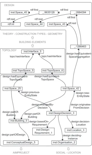
Using these semantic web technologies, one is able to describe AEC content in a semantic web graph. An example of an RDF graph was built for a design in Antwerp, Belgium. A small part of this graph is given in Fig. 2. It displays part of the description of one of five different designs made during an early design stage, exploring the desired topology in the design.
The graph describes two instances of adesign:Spaceconcept, how they are influenced by a certain design decision, which design they are part of, and how they are related to other geometry and spaces in the design. Both spaces are re-lated to one instance of adesign:DesignDecisionconcept, the one describing thedesign:newEntityStateand the other thedesign:previousEntityState. In this case, this describes how, at a specific time during the design process, the
inst:Space 25instance was replaced by theinst:Space 42instance, which is in fact an aggregation of three other spaces, namelyinst:Space 43,inst:Space 44
and inst:Space 45. This decision is an answer to an instance of the design: DesignRequirement concept, i.e. inst:DesignRequirement 1. This design re-quirement describes that each apartment should separate private spaces (e.g.
BUILDING ELEMENTS
THEORY - CONSTRUCTION TYPES - GEOMETRY
TOPOLOGY DESIGN design:partOf-Building design:partOf-Building inst:Space_25 inst:Building_5 inst:Space_42 inst:TopoSpace_5 inst:TopoSpace_6 inst:Interface_5 design:hasEquivalent-TopoSpace design:hasEquivalent-TopoSpace design:partOfDesign topo:hasInterface design:previous-EntityState design:changedBy-Decision design:decision-Location design:deciding-Instance design:basedOn-Requirement topo:hasInterface rdf:first inst:Space_45 _:9635128 _:2684394 _:1266463 inst:Space_43 inst:Space_44 rdf:nil design:hasEquivalent-SpaceAggregation rdf:rest inst:DesignDecision_3 inst:Design-Requirement_1 inst:ConceptualDesign_5 inst:Organisation_2 inst:Location_3 design:originates-FromDecision design:new-EntityState rdf:first rdf:rest rdf:first rdf:rest
AIMPROJECT SOCIAL - LOCATION
Fig. 2: Part of an RDF graph illustrating how design decisions in an architectural design project may be described.
sleeping) and more public spaces (e.g. living room). The result of the design de-cision is a space which follows the originally described topology of the building, but which is subdivided in an open living space and a secluded sleeping room, separated by a private staircase.
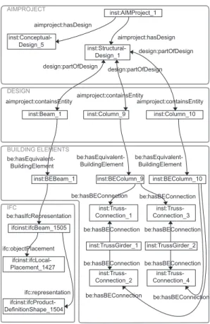
Another part of the same RDF graph, illustrated in Fig. 3, describes a part of the steel structure of the design. This RDF graph is directly related to the RDF graph shown in Fig. 2 through the inst:AIMProject 1 instance. Every design:Object instance (e.g. inst:Beam 1) is linked to its equivalent
be:BuildingElement, thereby explicitly connecting design properties to con-struction type properties, IFC properties, geometric properties, etc. Figure 3 further illustrates where to include a description of the geometric representation (ifc: representation) and the 3D placement (ifc:objectPlacement) of a
inst:Beam_1 inst:Structural-Design_1 inst:Conceptual-Design_5 inst:AIMProject_1 inst:BEBeam_1 ifcinst:ifcBeam_1505 ifcinst:ifcLocal-Placement_1427 ifcinst:ifcProduct-DefinitionShape_1504 aimproject:containsEntity design:partOfDesign inst:Column_9 aimproject:containsEntity aimproject:hasDesign aimproject:hasDesign be:hasEquivalent-BuildingElement be:hasEquivalent-BuildingElement be:hasEquivalent-BuildingElement be:hasIfcRepresentation design:partOfDesign design:partOfDesign aimproject:containsEntity ifc:objectPlacement ifc:representation AIMPROJECT DESIGN IFC BUILDING ELEMENTS inst:BEColumn_9 inst:Column_10 inst:BEColumn_10 inst:Truss-Connection_1 inst:Truss-Connection_3 inst:Truss-Connection_2 inst:Truss-Connection_4 inst:TrussGirder_1 inst:TrussGirder_2 be:hasBEConnection be:hasBEConnection be:hasBEConnection be:hasBEConnection be:hasBEConnection be:hasBEConnection be:hasBEConnection be:hasBEConnection
Fig. 3: Part of an RDF graph illustrating how a steel construction may be de-scribed as an aggregation of columns and beams.
building element, or how one may describe a truss consisting of two girders and two columns. By using a separate instance to describe the connection between two building elements, one is able to describe extra properties linked to this con-nection. When considering columns and beams, this may for instance introduce the possibility to make an explicit distinction between stiff and elastic joints.
All kinds of other information has been described similar to the way in which it is described above, including material properties, geometric properties, the-oretic information, etc. So far, this has resulted in a graph structure of about 100.000 RDF triples. Information that is not considered a direct part of the AEC domain may be connected to this graph as well. This may include for instance geographical information (e.g. GeoNames), people and organisation information (e.g. FOAF) or expert material information (e.g. MATOWL).
4
Using the information in applications
By explicitly describing AEC information in this graph structure, one obtains a semantically rich graph structure following explicitly logical terms. The main difference with existing approaches for design decision support is the ability to re-use this information within logic-based processes, thereby improving query and reasoning possibilities. Because this improves the way in which information can be found and handled, improvements may be found in decision support for the AEC domain as well.
4.1 Advanced querying of the information
SELECT ?x WHERE { ?x rdf:type design:Object .
?x be:hasEquivalentBuildingElement ?xBE . ?xBE be:hasBEConnection ?Conn . ?xBE rdf:type be:Column . ?yBE be:hasBEConnection ?Conn . ?yBE rdf:type be:TrussGirder .
?x design:originatesFromDecision ?decision . ?decision design:decidingInstance ?person . ?person soc:firstName “Pieter” . } design:Object be:Column be:TrussGirder ?x ?decision ?xBE ?yBE ?Conn rdf:type be:hasEquivalent-BuildingElement design:originates-FromDecision ?person “Pieter” design:deciding-Instance soc:firstName rdf:type rdf:type be:hasBEConnection be:hasBEConnection
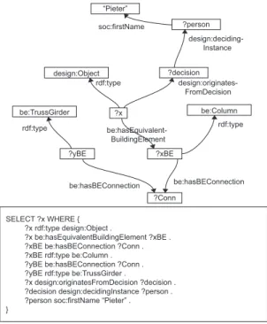
Fig. 4: Query for columns that are connected to a TrussGirder.
Using SPARQL [25], one is able to search for very specific information about the architectural design described. The kind of queries processed can be very diverse, depending on the diversity in the semantic structure of the queried RDF graph. The more detailed content is described in the queried RDF graph, the more detailed one can search through this content. For instance, one may search for spaces that were designed as an answer to a given design requirement. Executing such a query on the RDF graph previously discussed (Fig. 2), will then
return theinst:Space 42instance. Other, more complex queries can easily be constructed using the SPARQL query language. Figure 4 for instance illustrates how one may search for column designs that originated from a decision made by people with ‘Pieter’ as their first name, and that have a direct connection with a truss girder element.
4.2 Reasoning about the information
Using both the explicit (AIM facts) and the implicit (AIM rules) information about a building or a design, one can start a considerable reasoning process. In this case, the derivation of implicit information is done by a reasoning engine and not by the designer. Starting from the building elements ontology, one could for instance infer whether or not Vierendeel beams are present in a design. This is a specific type of beam developed by Arthur Vierendeel previously investigated in its historic context [28]. It is impossible to provide one single definition of a Vierendeel beam, however this kind of beam is most often referred to as a frame(work) with only vertical posts rigidly connected to the top and bottom chord.3
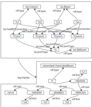
Starting from this definition of a Vierendeel beam and the information available in the RDF graph of a design, the appropriate rules may be written to infer if this graph contains an instance of such a Vierendeel beam. Figure 5 shows the graph pattern of a rule that may be able to provide this functionality, based on the information in the RDF graph discussed above. It says that IF
four elements are found, of which two are columns and two are beams, that are connected in a four-sided pattern through stiff joints, THEN these elements are part of a Vierendeel beam.
When this rule was checked on the RDF graph discussed above using our reasoning engine, several Vierendeel beams were identified, which is of no sur-prise, considering the rectilinear structure of the building and the way in which a Vierendeel beam was defined (Fig. 5). Obviously, other information may be inferred from the RDF graph as well, based on the information contained in this RDF graph. In a similar way, one could for instance also infer if a room can be reached from within another room, if an architectural theory may be associated to a design, if the design contains significant similarities with other designs (pro-vided that an RDF graph of this second design is available of course), etc. A more detailed overview of how semantic rule languages may be deployed in an AEC context, can be found in [16] and [17].
5
Parallel descriptions of information
The above investigation gives an indication of how semantic web technology may provide support in the design and construction process for the AEC domain
sim-3
In its original patent, the Vierendeel beam was described by Arthur Vierendeel as a series of rectangular frames“in which the diagonals are removed and the vertical members rigidly connected to the booms by rounded pieces in such manner that the booms and vertical members form practically one piece”[29].
?x2 ?x3 ?x4 be:Column be:Beam be:StiffJoint ?x1 ?x ?Conn1 be:hasBEConnection be:jointType
be:jointTypebe:jointTypebe:jointType
rdf:type be:hasBEConnection
be:hasBEConnection be:hasBEConnection
?Conn2 ?Conn3 ?Conn4 rdf:type rdf:type rdf:type rdf:type
log:implies vierendeel:VierendeelBeam ?t _:2649853 _:9564324 _:1683549 rdf:nil ?x2 ?x4 ?x3 rdf:type rdf:first rdf:first rdf:first rdf:first rdf:rest rdf:rest rdf:rest rdf:rest _:1683549 ?x1
Fig. 5: The above rule describes that this certain configuration of beams and columns constitutes a Vierendeel beam. Note that this graph has no intention to capture the exact definition of a Vierendeel beam. It merely aims at illus-trating how extra information may be inferred from an RDF graph within an architectural design process using rules.
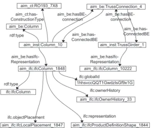
ilar to how BIM provides this support currently. Nevertheless, the most impor-tant improvement of deploying semantic web technology over current approaches might be the possibility to reach a more appropriate level of interoperability. In the light of the discussion about BIM and interoperability earlier, we investi-gated how we could describe the same concepts and objects in the web of AIM information according to different schemas and interlink these descriptions so that this information may become appropriately reusable or interoperable. An example of parallel descriptions of the same elements can be found in the de-scription of a building element using the AIM building element ontology and the IFC ontology (Fig. 6).
The same concept, namely one of the columns in the design of the Staties-traat, is described through multiple concepts, namelyaim inst:Column 10and
aim ifc:IfcColumn 1848. Both concepts are linked, with the former further be-ing described usbe-ing the AIM buildbe-ing elements ontology, and the latter usbe-ing the IFC ontology. Although these parallel descriptions do not incorporate the same information, they illustrate the interoperability problem appropriately. Whereas IFC provides one standard schema that needs to be reinterpreted and remodelled
aim_inst:Column_10 aim_ifc:ifcColumn_1848 aim_ct:RO193_7X8 aim_be:TrussConnection_4 aim_be:Column rdf:type aim_be:hasIfc- Representation ifc:IfcColumn rdf:type aim_ifc:ifcLocalPlacement_1847 ifc.objectPlacement aim_ifc:ifcProductDefinitionShape_1844 ifc:representation aim_ifc:ifcOwnerHistory_33 ifc:ownerHistory 1hhsvccQQT1GwdzIsGf9x1G ifc:globalId aim_ct:has-ConstructionType aim_be:has-ConnectedBE aim_be:hasBE-connection aim_be:hasBE-connection aim_inst:TrussGirder_1 aim_be:has-ConnectedBE aim_ifc:ifcColumn_10222 aim_be:hasIfc- Representation
Fig. 6: Part of an RDF graph illustrating how the same column can be de-scribed through several distinct subgraphs, in this case as part of an AIM building element graph (aim inst:Column 10) and as part of an IFC graph (aim ifc:IfcColumn 1848).
into another schema, the semantic web allows to combine schemas independently, thereby describing the same concepts according to different schemas. An appli-cation on top of this web of information may then rely on information stemming from both schemas as required. For the example in Fig. 6, a BIM environment may rely solely on the information represented by the IFC graph, whereas a sim-ulation environment may rely on very specific parts of the IFC information (e.g. geometry) combined with construction type information following the building element ontology. Changes made in the BIM environment are reflected automat-ically in the simulation environment, and vice versa, resulting in the required level of interoperability.
However, in many cases, applications deploy different schemas to represent the same information. This is most often illustrated in the context of 3D geome-try. The same geometry can be described in many different ways corresponding to the context in which it is used. One schema may describe a sphere for in-stance through its centre and radius, whereas another schema may describe it through a circular arc and a central axis, or maybe through a triangular mesh. As is shown in Fig. 7, this information can be combined into one semantic web. Changing part of this information, however, may lead to inconsistencies in the description.
An alternative approach is to rely on rules and an inference engine to infer the duplicate information on-demand, as we indicated earlier in [17]. One geometric description is available in an RDF graph and descriptions following a different schema are generated on demand by a rule engine and a set of inference rules.
inst:IfcWallStandardCase inst:Matrix_2
inst:Matrix_1
(inst:T1 inst:T2 inst:T3 inst:T4 inst:T5 inst:T6 inst:T7 inst:T8 inst:T9 inst:T10 inst:T11 inst:T12)
(inst:T2 inst:T3 inst:T4 inst:T5 inst:T6 inst:T7 inst:T8 inst:T9 inst:T10 inst:T11 inst:T12)
“4000” “280” inst.T1 “2400” inst:IfcLocalPlacement_1 ifc:object-Placement x3d:sizeX x3d:sizeZ x3d:translation-Matrix stl:triangles rdf:first rdf:rest x3d:rotation-Matrix x3d:sizeY inst:ifcAxis2-Placement2D_1 inst:IfcExtrudedAreaSolid ifc:representation ifc:position ifc:position inst:IfcLocal-Placement_2 inst:IfcAxis2-Placement3D_1 ifc:sweptArea
(inst:XCo1 inst:YCo2 inst:ZCo3) (inst:XCo1 inst:YCo2 inst:ZCo3)
(inst:XCo1 inst:YCo2 inst:ZCo3) stl:vertex1 stl:vertex2
stl:vertex3
Fig. 7: Part of an RDF graph illustrating how the geometry of a box-shaped wall is described according to the IFC schema (extruded area solid), the X3D schema (rotation and translation matrix) and the STL schema (mesh).
The information in the alternative schema is thus available implicitly in the RDF graph.
One may for instance consider how an application stores geometry in an RDF graph following the IFC ontology. When combined with the appropriate rule set, namely one that enables the inference of the same geometric information following the STL ontology, one automatically has also this second description at his or her disposal. An application requiring the input of geometry in the STL schema can rely on this inferred STL/RDF graph. Changes made to the geometry in this STL-based application can be stored in a separate RDF graph. A second set of IFC-to-STL conversion rules provides interoperability of information back to the original IFC-based application. This approach could similarly be applied to other, non-geometric information. The initial investigation documented in [17] gives an appropriate overview of this rule-based conversion approach. Further investigations of this approach are however needed to conclude for the practical applicability of this approach.
6
Conclusion
The automation of design and construction in the AEC domain has gone through significant developments and improvements over the past years. The combina-tion of BIM as a central building informacombina-tion management platform and IFC as
an interoperability language was in this context suggested as a valid approach for improving efficiency and decreasing the amount of errors and/or misconcep-tions in the design and construction process. Recent use-case researches indeed indicated such an improvement of the design and construction process. How-ever, it was also shown that these improvements are mainly generated by the mere availability of a central information modelling environment, such as BIM, instead of by the level of interoperability generated by IFC.
As semantic web technology promises a similar level of interoperability for information on the World Wide Web, we started an investigation on the applica-bility of semantic web technology as a possible alternative approach for inducing improvements through an appropriate level of interoperability. A preliminary architectural information modelling framework was set up, relying on a combi-nation of interconnected facts and rules. We have shown how a design decision support may be set up on top of these facts and rules, similar to the way in which support applications are provided on top of BIM models and/or IFC models.
Additionally, we investigated to what extent the interoperability issues cur-rently present in IFC may be encompassed using such a semantic web approach. This investigation showed us able to describe information using separate de-scription schemas and connect them, thereby enabling a certain level of inter-operability. As separate schemas can be combined, one could for instance bring together a schema typically deployed in a BIM environment (e.g. IFC), and a schema typically deployed in a simulation environment (e.g. energy analysis). Finally, we showed how rule languages may enable the combination of schemas that describe the same kind of information differently. The initial test cases in this regard proved successful, although future research is needed to conclude on the practical applicability of the approach.
7
Acknowledgements
This research is a part of research at the UGent SmartLab research groups, sup-ported by both the Department of Electronics and Information Systems and the Department of Architecture and Urban Planning of Ghent University. The au-thors gratefully acknowledge the funding support from the Research Foundation - Flanders (FWO).
References
1. C.M. Eastman, P. Teicholz, R. Sacks, K. Liston, BIM Handbook: A Guide to Build-ing Information ModelBuild-ing for Owners, Managers, Architects, Engineers, Contrac-tors, and FabricaContrac-tors, John Wiley and Sons, Hoboken, 2008.
2. B. Becerik-Gerber, S. Rice, The perceived value of building information modeling in the US building industry, ITcon 15 (2010), pp. 185-201, 2010.
3. T. Liebich, Y. Adachi, J. Forester, J. Hyvarinen, K. Karstila, K. Reed, S. Richter, J. Wix, Industry Foundation Classes IFC2x Edition 3 Technical Corrigendum 1, http://www.iai-tech.org/ifc/IFC2x3/TC1/html/index.htm (last accessed on 24th. June 2010).
4. T. Pazlar, Z. Turk, Interoperability in practice: geometric data exchange using the IFC standard, ITcon 13 (2008), pp. 362-380, 2008.
5. R. Verstraeten, P. Pauwels, R. De Meyer, W. Meeus, J. Van Campenhout, G. Lateur, IFC-based calculation of the Flemish energy performance standard, In A. Zarli & R. Scherer (eds.): Proceedings of the 7th European Conference on Product and Process Modelling (ECPPM): eWork and eBusiness in Architecture, Engineering and Construction, Taylor & Francis Group, London, 2008, pp. 437-443.
6. T. Berners-Lee, J. Hendler, O. Lassila, The Semantic Web, Scientific American 284 (5) (2001) 35-43.
7. P. Pauwels, R. Verstraeten, R. De Meyer, J. Van Campenhout, Semantics-based design: can ontologies help in a preliminary design phase?, Design Principles and Practices: An International Journal 3 (5) (2009) 263-276.
8. M.P. Gallagher, A.C. O’Connor, J.L. Dettbar, L.T. Gilday, Cost Analysis of Inad-equate Interoperability in the U.S. Capital Facilities Industry, NIST Report GCR 04-867, National Institute of Standards and Technology (NIST), 2004.
9. ISO 10303-11:1994 Industrial automation systems and
integra-tion - Product data representation and exchange - Part 11:
De-scription methods: The EXPRESS language reference manual,
http://www.iso.org/iso/iso catalogue/catalogue tc/catalogue detail.htm?c snum-ber=18348 (last accessed on 24th. June 2010).
10. ISO 10303 Product Data Representation and Exchange,
http://www.tc184-sc4.org/SC4 Open/SC4%20Legacy%20Products%20 %282001-08%29/STEP %2810303%29/ (last accessed on 24th. June 2010).
11. International Alliance for Interoperability, http://www.iai-tech.org/ (last accessed on 24th. June 2010).
12. Web3D Consortium, X3D International Specification Standards,
http://www.web3d.org/x3d/specifications/x3d/ (last accessed on 24th. June 2010).
13. 3D Systems, Stereolithography interface specification, 1989.
14. A. Yurchyshyna and A. Zarli, An ontology-based approach for formalisation and semantic organisation of conformance requirements in construction, Automation in Construction 18 (8) (2009) 1084-1098.
15. J. Beetz, J. van Leeuwen, B. de Vries, IfcOWL: A case of transforming EXPRESS schemas into ontologies, Artificial Intelligence for Engineering Design, Analysis and Manufacturing (AI EDAM) 23 (1) (2009) 89-101.
16. P. Pauwels, D. Van Deursen, R. Verstraeten, J. De Roo, R. De Meyer, R. Van de Walle, J. Van Campenhout. A semantic rule checking environment for building performance checking, Automation in Construction (2010 - to appear).
17. P. Pauwels, D. Van Deursen, J. De Roo, T. Van Ackere, R. De Meyer, R. Van de Walle, J. Van Campenhout. 3D information exchange over the semantic web for the domain of architecture, engineering and construction, Artificial Intelligence for Engineering Design, Analysis and Manufacturing: Special Issue on Representing and Reasoning About 3D Space 25 (4) (2011 - to appear).
18. B. Kraft, M. Nagl, Visual knowledge specification for conceptual design: definition and tool support, Advanced Engineering Informatics 21 (2007) pp. 67-83.
19. W3C Semantic Web Portal, http://www.w3.org/2001/sw/ (last accessed on 24th. June 2010).
20. F. Manola and E. Miller, RDF Primer - W3C Recommendation 10 February 2004, http://www.w3.org/TR/rdf-primer/ (last accessed on 24th. June 2010).
21. D. Brickley and R.V. Guha, RDF Vocabulary Description Language 1.0: RDF Schema - W3C Recommendation 10 February 2004, http://www.w3.org/TR/rdf-schema/ (last accessed on 24th. June 2010).
22. D.L. McGuinness and F. van Harmelen, OWL Web Ontology Language Overview - W3C Recommendation 10 February 2004, http://www.w3.org/TR/owl-features/ (last accessed on 24th. June 2010).
23. J. Grant and D. Beckett, RDF Test Cases - W3C Recommendation 10 February 2004, http://www.w3.org/TR/rdf-testcases/ (last accessed on 24th. June 2010). 24. D. Beckett and T. Berners-Lee, Turtle - Terse RDF Triple Language - W3C Team
Submission 14 January 2008, http://www.w3.org/TeamSubmission/turtle/ (last ac-cessed on 24th. June 2010).
25. E. Prud’hommeaux and A. Seaborne, SPARQL Query Language for RDF - W3C Recommendation 15 January 2008, http://www.w3.org/TR/rdf-sparql-query/ (last accessed on 24th. June 2010).
26. UGent MultiMediaLab, IFC-to-RDF Service, http://ninsuna.elis.ugent.be/Ifc-RDFService (last accessed on 24th. June 2010).
27. UGent MultiMediaLab, SPARQL endpoint for IFC/RDF graphs,
http://ninsuna.elis.ugent.be/SPARQLEndpoint/ (last accessed on 24th. June 2010).
28. K. Verswijver, R. De Meyer. 2010. Past and present characteristics of Vierendeel’s poutre arcades. Proceedings of the First International Conference on Structures and Architecture, July 2010, Guimares, Portugal.