There followed studies explaining mechanical strength, cold-drawing properties,Rlm-forming capa-bilities, cohesion within Rlms and their adhesion to a wide variety of substrates, pigment binding, and the mechanisms of cross-linking processes.
Reiner was theRrst to appreciate that the difference between a synthetic macromolecule and a biopolymer was merely that of environment. In consequence his work on microbacter and cellular transformations must now be considered to be the foundation for much of today’s clinical and pathological practice.
The FOM Foundation group in Amsterdam, under the stewardship of Meuzelaar, expanded theReld of application of PGC in parallel with their pioneering work in pyrolysis/mass spectrometry. There, their initial focus was on a broad spectrum of natural polymers. Wheals, of the British Metropolitan Police Forensic Laboratory, introduced PGC in criminology and de-veloped techniques that formed a basis for standard practice in forensic laboratories. Results are now gener-ally accepted as evidence in many criminal jurisdictions. The virtue of the very small samples needed for the vast majority of diagnoses has seen adoption of PGC, conducted under very carefully controlled conditions, for the preservation of many art gallery and museum exhibits. For example, deteriorating ancient varnishes and pigments have yielded their secrets and pictures may be cleaned and/or restored without further dam-age, which will beneRt the generations still to come. Environmental and ecological applications are now coming to the fore. The analysis of occlusions of harmful volatile organics on air-borne particulates has contributed much to our understanding of their signiRcance in the context of respiratory problems.
Bracewell was among theRrst to develop PGC for the assessment of soil fertility. More recently, De Leeuw graphically demonstrated that reasonably vol-atile organics such as polycyclic and halogenated hydrocarbons could be excised from very complex matrices (e.g. soils or sediments) bySash evaporation by imposing a millisecond thermal ramp on the sample. Jones and Vanderborgh employed PGC in conjunc-tion with other pyrolytic studies in their elucidaconjunc-tion
of coals. They demonstrated that their apparent het-erogeneities were due to guest markers of the environ-ments of both the initial debris and the maturation cycle then occluded in a formal cross-linked, spiral double-ladder polymer. An outcome of their work was a proposal for a ‘down-hole’ mole chromato-graph containing a miniature laser pyrolysis cell designed to be lowered into a petroleum exploration, pilot drill hole for real-time in situ stratigraphic monitoring of hydrocarbons. Such an approach must certainly be quicker and cheaper than core extraction and subsequent off-site analysis.
In the light of the diversity of applications given here, it is more than apparent that PGC’s potential is only limited by the wit and imagination of the educated user.
Conclusions
Despite the early stigma of unreliable and dirty analy-sis, PGC survived because of the dedication of a small handful of workers who were convinced that most practitioners were to blame for their failures rather than the tool they purported to use.
The method has re-emerged as an active member of the analytical chemist’s armoury. This is handsomely substantiated by each successive issue of theJournal of Analytical and Applied Pyrolysis.
Material gain has resulted from the adoption of hyphenated instrumentation (e.g. coupling with high speed quadrupole mass spectrometry or Fourier transform infrared spectrophotometry) and has most certainly elevated the status of the technique. See also: II/Chromatography: Gas: Detectors: Mass Spectrometry; Detectors: Selective. III/Archaeology: Uses of Chromatography in. Art Conservation: Use of Chromatography in. Humic Substances: Gas Chrom-atography. Space Exploration: Gas ChromChrom-atography.
Further Reading
Wampler TP (1995) Applied Pyrolysis Handbook. New York: Marcel Dekker.
Sampling Systems
I.W.Davies, Cambridge, UK
Copyright^ 2000 Academic Press
Introduction
The term ‘injection’ encompasses techniques used to transfer samples of gases, liquids and solids on to the
sites) must be minimized. The operating conditions, e.g. column temperature and solvent used, should not inSuence injection, and retention times and peak areas should be reproducible.
Injectors for pyrolysis-GC and supercritical Suid chromatography will not be dealt with in this article.
Gas Samples
For accurate quantitative analysis gas samples are nearly always introduced by means of a valve Rtted with an internal or external sample loop. Although the construction of gas-sampling valves takes a var-iety of forms, the principle of operation is common to all. In one conRguration the gas passes through a loop ranging from approximately 0.1 to 10 mL in size while the carrier gas passes into the column. In the other conRguration, the sample is isolated and the carrier gas stream sweeps the sample trapped in the loop onto the column. If care is taken to control the temperature and pressure of the gas, such valves offer very high reproducibility and all quantitative analysis can be performed by external calibration. They can also be readily automated for plant analysis. For further details see Gas analysis by gas chro-matography. Gas samples can be injected on to col-umns by means of gas-tight syringes but the precision is much poorer than that with loop valves and their use is not recommended for accurate quantitative analysis.
Solid Samples
Solid samples are best dealt with by dissolving them in a suitable solvent and treating them as liquid sam-ples. It is not always possible toRnd a suitable solvent or the ‘sample’ might be in a matrix such as soil or sand. For such materials packed columns have been Rtted with capsule samplers where the capsule is dropped into a hot vaporizing zone and is withdrawn by a magnet after analysis.
Liquid Samples
The majority of samples analysed in the laboratory are in liquid form, as would be expected from the range of compounds likely to be amenable to GC. Most of this article is, therefore, concerned with the introduction of liquid samples onto packed and capillary columns.
Packed Columns
The equilibrium distribution of analyte between the two phases should be independent of sample size.
However, as sample size increases isotherms become nonlinear and peaks become broader and distorted, which leads to reduced resolution. A column is re-garded as overloaded if its efRciency is reduced by 10%. The approximate maximum vapour volume (Vmax) of an individual solute not leading to
detect-able peak broadening can be calculated from:
Vmax"
0.02;VR
(N [1]
whereVRis the retention volume andNis the number
of theoretical plates.
For a component eluted with a retention volume of 150 mL (after 5 min at 30 mL min\1) from a packed
column of 3000 plates,Vmaxis approximately 50L,
equivalent to 0.1L liquid.
More empirically, initial bandwidth should be not more than a tenth of the width of the narrowest peak and the smaller the sample the better the chromatog-raphy. The analyst should inject microgram quantit-ies. Since 0.1L corresponds to 100g for a liquid of unit density, dilute solutions are necessary if only a few micrograms are required.
Vaporizing Injector
Injection is usually performed with a syringe, through a replaceable, self-sealing plastic or rubber septum into an injector of approximately1
4in i.d. (6 mm). The
column is attached either to the base of the injector or inserted within it. In the former instance metalRttings are usually used. The injector is heated to facilitate rapid transfer of sample to the column (‘Sash vapor-ization’). To limit sample decomposition on hot metal surfaces, the injector usually contains a glass liner that can be replaced when dirty and can be regularly deactivated by silylation. The injector temperature should be high enough to vaporize the components of interest; as the temperature required to do this is rarely known, the temperature is usually set to ca. 503C above the oven maximum.
column oven). The injector temperature should not exceed the maximum operating temperature of the stationary phase.
Injectors are rarely heated uniformly; the heating block encloses only part of the injector body and the rest is heated by conduction. Sometimes, to reduce septum decomposition and bleed, the injector is de-signed so that the septum nut is colder than the rest of the injector. Carrier gas enters the injector through an inlet in the jacket enclosing the injector liner. Usually it is warmed by passage through a coil of stainless-steel tubing wound round the injector heating block; this helps ensure that vaporized sample does not en-counter cold carrier gas.
Syringes
Plunger-in-barrel (5}1000L) and plunger-in-needle (0.5 or 1L) syringes are widely available. The latter are used to dispense quantities up to 1L, although the 5L syringe can be used to dispense 0.3L with reasonable repeatability, especially if used on an autosampler, although the amount injected is not necessarily that indicated on the graduated scale. With the plunger-in-barrel syringe, needle volume is relevant if the injector temperature is above the solvent boiling point. When the plunger-in-needle syringe is used for vaporizing injection the needle temperature starts to increase when the needle pen-etrates the septum; the sample should, therefore, be partly withdrawn into the needle, otherwise part will be discharged into the septum.
It is difRcult to determine the volume of sample remaining in the needle after vaporizing injection. Much will be forced from the syringe by explosive vaporization; this will cool the needle (passage of cold solution; absorption of latent heat of vaporization) and some sample will inevitably evaporate from in-side the needle, depositing involatile residue. Such problems decrease in signiRcance with increasing in-jection volume (but are immensely signiRcant in cap-illary GC). Passage of sample through a hot steel needle can lead to decomposition of unstable sample components.
These considerations have led to the development of several different syringe-handling techniques. Filled needle The plunger is moved quickly up and down to eject air and the syringe is removed from the sample with the plunger fully depressed. The sample is injected by pushing the syringe through the septum without moving the plunger. The needle volume only is injected, some sample is inevitably ‘injected’ into the septum, and much of the sample evaporates from the inner surface of the needle.
Cold needle The sample is withdrawn into the bar-rel and the syringe is inserted through the septum and the plunger depressed immediately. It is hoped that most of the sample passes through the needle in the liquid state with the needle still cold. Sample remain-ing in the needle, however, evaporates as the needle warms.
Hot needle Performed as above but the needle is left to warm in the injector for 3}4 s before rapid depress-ion of the plunger. Much of the sample is rapidly ejected from the needle as a result of rapid explosive vaporization in the Rrst stages of injection. The amount of sample evaporating from the inside of the needle is probably less than for cold needle injection. SolventWush A small volume (c. 1L) of solvent is withdrawn into the barrel, then the sample (possibly with an air barrier between the two to prevent mix-ing). Injection is performed by hot or cold needle injection. The sample can be sandwiched between two portions of solvent.
AirWush As above, but with air in place of solvent. However, the continuous introduction of oxygen into the column is not recommended for high temperature work because of the deleterious effect on the station-ary phase.
Air and solvent As above, but with both air and solvent.
Sample Vaporization
It is not clear what happens to the sample inside the injector. Almost certainly it enters as liquid droplets. Although it is widely assumed that vaporization pro-ceeds almost instantaneously, it is unlikely that enough energy is available, certainly in the carrier gas, to supply the latent heat required. If the liquid sample hits the wall of the injector, instant evapor-ation of the solvent in contact with the wall probably forces the sample away from the wall, i.e. the source of heat. Even if the sample is injected into a hot packing only a small amount of heat is available and the sample probably evaporates quite slowly.
Disadvantages
divert a small amount of carrier gas over the septum surface and to exhaust this stream to atmosphere.
Capillary Columns
Typical carrier gas Sow rates for 0.3 mm i.d. wall-coated open-tubular (WCOT) columns are less than 2 mL min\1. The vapour from 1L solvent occupies
approximately 0.5 mL at 2503C. If the injector vol-ume is 1.0 mL and Sow of one injector volume of carrier gas sweeps all the vapour on to the column (no diffusion of sample with carrier gas), transfer time is
530 s}considerably more than the 5 s peak widths typically encountered in capillary GC. In reality, sample concentration in the carrier gas decreases exponentially because carrier gas diffuses into the sample vapour cloud; this adds a tail to the band widths given above.
There is clearly a need for a different method of injection or a means of narrowing the band-width.
Split Injection
Split injection, or indirect sampling after vaporizing injection, was the earliest attempt to solve this prob-lem. For many years it was the only technique avail-able; it is still very popular.
CarrierSow through the injector is split; a small proportion is directed into the column and the re-mainder is vented. When the sample is vaporized a small proportion of the vapour cloud only is trans-ferred to the column; this reduces the time during which sample is transferred into the column. The split ratio is:
carrier flow to atmosphere flow through the column
Most of sample is lost so the technique is not suitable for trace analysis (sample components present at levels below 0.01%) but it is well suited for complex, relatively low-boiling mixtures, such as gasoline, con-taining many components in the range 0.01}10%.
Originally it was widely believed that the splitter eliminated the column overloading believed to be responsible for excessive bandwidths. This could have been achieved by diluting the sample. Although the capacities of capillary columns are well below those of packed columns, the effect of overloading on band broadening is negligible compared with the ef-fect of slow sample transfer.
Using eqn [1] for a 0.32 mm i.d. column with 90 000 theoretical plates and a component for which
VR is 10 mL (elution after 5 min at 2 mL min\1)
shows thatVmaxis approximately 1L (equivalent to
0.002L liquid). This formula gives a pessimistic result for capillary columns and 15L is more realis-tic. Even so, to reduce 0.5 mL vapour to 0.015 mL requires a split ratio of 33 : 1; to take account of sample diffusion in the carrier gas, practical split ratios must be considerably higher ('100 : 1).
Splitter Design Features
Splitting should be reproducible; reproducibility is, however, affected by many factors.
The sample must encounter inert surfaces only }the injector usually contains a glass liner. Splitting should be linear and nondiscriminatory, i.e. sample should be vaporized rapidly and pass the column inlet as a concentrated, homogeneous plug. Because of the limited heat available, the sample is unlikely to be vaporized instantaneously. Droplets can be carried into the column irreproducibly and evaporation of droplets in the injector leads to fractional distillation. Such behaviour can be overcome by using a mixing device, e.g. packing the liner with glass wool or glass beads. This can cause dilution of the sample (loss of sensitivity) and discrimination owing to adsorption, condensation and decomposition. Adsorption can be reduced by silylation in situ (because packing an injector with silylated glass wool results in fracture of the glass Rbres and exposure of new active sites); condensation might be eliminated by increasing the temperature.
Packed injector liners were introduced as thermal reservoirs to encourage rapid vaporization. Calcu-lations show, however, that except for volumes of
ca. 0.5L, the amount of heat available from carrier gas and liner packing is well below that required for vaporization. Heat is available from the injector wall, but when solvent droplets touch this they are instant-ly repelled by vaporization of the small amount of solvent in (instantaneous) contact with the wall. It is now accepted that the packing provides a surface that retains the entire sample during slow, controlled evaporation.
It has been suggested that a buffer volume beyond the split point reduces pressure Suctuations that might lead to variations in carrierSow and split ratio; although such buffer volumes do indeed help dispel pressure waves, their beneRts have been disputed.
Injection Technique
The most reproducible injections with least discrim-ination are given by the ‘hot needle’ (1.5}2L) and ‘solventSush’ techniques. Needle-in-plunger syringes cannot be used because samples start to evaporate as soon as the syringe enters the injector, leading to fractionation and discrimination. Injector temper-ature should be near the boiling point of the sample’s least volatile components or discrimination might arise even from a well-designed splitter, especially at low ((100 : 1) split ratios. If it is essential to use a low split ratio, e.g. in trace analysis, then a high temperature must be used. For unstable compounds a low injector temperature and high split ratio are desirable.
If the column temperature is below the solvent boiling point and the solvent vapour pressure is sufRciently high (depending on injection size and split ratio), sample can condense in the column. The re-sulting sudden drop in pressure leads to suction of material from the injector and the split ratio will vary. Similar effects might lead to condensation in gas lines control valves, etc., leading to ghost peaks later in the analysis as the material diffuses back into the injector. The column should be mounted with its inlet at, or near, the injector base to minimize the volume from which back-diffusion might occur. For the largest signal, needle length should be such that sample is released at the column inlet (10 mm gap). The effect of needle length on response should be checked ex-perimentally.
It is worth varying the split ratio over a wide range } a high split ratio might result in such rapid Sow through the injector that the sample passes the col-umn inlet while still in the form of a concentrated plug. The vapour cloud concentration can be opti-mized to prevent back-diffusion by use of an injector liner compatible with injection. For low split ratios (10 : 1}50 : 1) and 8 cm liner typical values are: a 1.5 mm i.d. liner for 0.4L injection, a 2.0 mm i.d. liner for 0.6L injection, and a 3.5 mm i.d. liner for 2.0L injection.
Advantages and Disadvantages
The advantages of the splitter are simplicity } for qualitative and semiquantitative work very little can go wrong. Its major disadvantage is discrimination: inhomogeneous mixing of carrier gas and sample and
different rates of evaporation and incomplete evapor-ation of components of different volatility inside the syringe needle and from droplets in the injector body. Other disadvantages include unsuitability for temper-ature-sensitive and involatile compounds and low sensitivity for trace analysis. Condensation of solvent inside the column, pressure surges on injection and changes in the volumes of carrier and sample gases on moving from injector to oven at different temper-atures reduce reproducibility and mean that the ac-tual split ratio is never that calculated from gasSow rates. To minimize errors from these effects, the oper-ating conditions must be kept as constant as possible and internal standards should be used for quantitative analysis. Venting most of a sample to atmosphere may represent a safety hazard.
Reconcentration of Bands Broadened by Split Injection
Cold trapping If the difference between the column temperatures at injection and elution is '453C (approx.), then material of low volatility is retained by the cold column and migrates only a small distance before transfer from the injector is complete; it starts to migrate only when the oven temperature is in-creased. The extent of reconcentration depends on the ratio of the migration rates of the volatile and involatile components. Because the migration speeds of most components are halved if the temperature is reduced by 153C, there is a concentration factor of 2 for each 153C difference between the column tem-peratures at injection and elution. A difference of 803C will always render any band broadening result-ing from injection undetectable and in normal cir-cumstances a difference of 40}603C will be sufRcient.
Splitless Injection with Solvent
Trapping
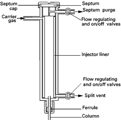
If solvent is injected by vaporizing injection into a col-umn maintained at a temperature below the solvent boiling point, the vapour leaving the injector will, under certain conditions, condense in the column inlet. Splitless injection incorporating solvent trap-ping exploits this behaviour. The injector used is similar in design to some splitters (Figure 1), in that it has outlets to the column and splitter and a septum purge. During injection and for a short time after-wards (so-called ‘splitless period’) the injector and (often) septum purge vents are kept closed and the only exit from the injector is onto the column. At other times the vents remain open.
Figure 1 The split}splitless injector.
the splitless period. The vent Sow is set to 20} 100 mL min\1. The purpose of the septum purge
(1}2 mL min\1) is as described above.
For injection, the oven temperature is set to
4203C below the solvent boiling point (the optimum temperature is best determined experimentally), the vents are closed and the sample (1}2.5L) injected. After the splitless period (20}60 s) the vents are opened and chromatography initiated. The conden-sed solvent in the column acts as a thick layer of stationary phase, which dissolves the sample’s com-ponents. Carrier gas passing over theRlm is rapidly saturated with solvent vapour so all solvent evapor-ation occurs at the rear of the Rlm. As the length of the solventRlm decreases, sample components remain in solution in the narrowing band of liquid. When the last trace of solvent evaporates, the sample compo-nents will have been concentrated into a narrow band from which to start chromatography.
Exploitation of solvent trapping is not limited to injection of liquids. If 2}3L solvent is condensed in the column inlet it can be used to trap volatile organic compounds injected as a vapour immediately after-wards (i.e. before the solvent has evaporated). This could be useful for headspace analysis.
Injection Technique
Initial vaporization of the sample is identical with that in split injection and so many of the factors described above are relevant. The text below covers points of special relevance to obtaining satisfactory solvent trapping.
The solvent boiling point should be 203C below the column temperature at the start of chromatography.
Because, irrespective of oven temperature, the solvent will condense quantitatively only if its vapour pres-sure is sufRciently high, the amount of solvent injec-ted must be adequate (1}2.5L is usually sufRcient); excessive dilution of the sample vapour cloud with carrier gas should be eliminated by use of an injector liner of appropriate volume. If the solvent boiling point is too high the solvent peak might interfere with those of the sample components, although this might be overcome by choosing a solvent only sparingly soluble in the liquid phase and thus eluted quickly.
To reduce discrimination against less volatile sample components 90}95% of the sample must be transferred to the column. Because of dilution of sample in the injector, such transfer requires a split-less period four times that necessary to transfer un-diluted sample; this could lead to excessive solvent tailing. In practice, the pressure drop caused by sol-vent condensation results in sample being sucked into the column faster than would otherwise occur; this offsets band broadening caused by sample dilution such that it is rarely a problem for sample volumes
(4L. The optimum splitless period should be de-termined experimentally, starting atca.20}30 s and increasing it for larger volumes and less volatile com-pounds. Optimum column position, needle length, etc., must also be determined experimentally.
If the injector has a separate septum purge and its Sow is maintained sufRciently low, it may be possible to leave it open during injection without signiRcant loss of sample, thus almost eliminating the effects of septum bleed.
Advantages and Disadvantages
The technique is reasonably simple, and applicable to dilute samples, trace analysis and to volatile and involatile compounds; it is reasonably good for quantitative analysis. Because the sample can be transferred to the column over a longer period than is possible for split injection, the injector can be maintained at a lower temperature, rendering the technique more suitable for the analysis of thermally unstable compounds.
solventRlm can also result in variations in retention data, especially for different solvent volumes.
Cold On-Column Injection
This term denotes direct transfer of liquid sample into the column inlet, i.e. the sample is introduced to the column as a liquid rather than being evaporated from the syringe. Because the technique exploits solvent trapping, the column inlet must be kept cool, i.e. 103C below the solvent boiling point (cf. 203C below for splitless injection). In this way explosive evapor-ation of sample does not lead to its beingSushed back into the cold injector where it might be lost com-pletely or from where it might slowly drift back on to the column, leading to band broadening. The point of injection must, however, be positioned within the temperature control of the oven, usually 5}10 mm from the oven wall (a greater distance increases the chance of the needle being heated). The original de-sign had the injector body only cooled. Later versions had the addition of secondary cooling so that during injection the section of column in the oven, and into which injection took place, could be cooled, thus increasing the range of temperatures over which the technique could be used. The injector body should be isolated from the hot insulating material of the oven top.
Injection is performed with a special syringe with a needle of o.d. 0.05 mm less than the column i.d. (so it does not plug the column and restrict carrier gas Sow. The syringe is inserted into the column via a seal that prevents escape of carrier gas (column head pressure should be maintained). The carrier gas line to the injector should be through wide-bore tub-ing so that any slight leakage through the needle-seal does not affect the column head pressure. For borosilicate columns needle entry into the column is aided by chamfering the column inlet. This is not possible with fused silica because the column wall is too thin.
Injection speed depends on the injector. Better quantitative results are obtained by rapid injection, sending the sample well into the column to reduce the possibility of sample adhering to the needle and being removed when the syringe is withdrawn. Reproduc-ible injection of 0.5}8L is possible. Smaller quan-tities are more difRcult because they cannot be mea-sured accurately with a 5 or 10L syringe and the speed at which the sample is ejected from a 0.5 or 1L syringe is insufRcient to carry the sample well away from the syringe needle. If fast injection of these sample volumes is performed at oven temperatures near the solvent boiling point there are no problems with expanding clouds of solvent vapour being forced
back past the syringe needle (with consequent sample loss). At higher temperatures it is essential that the injector is Rtted with secondary cooling so that sample is ejected into a cool section of the column. If secondary cooling is not available, it might be neces-sary to inject slowly at or about the solvent boiling point so that the vapour formed on evaporation from the column wall (not from the syringe needle) is carried away as it is formed. Some loss on the needle usually accompanies this technique, but losses are less than if the sample were to be forced explosively back into the injector body. Losses might be reduced by increasing the carrierSow and/or leaving the syringe in the injector for a few seconds after injection, to promote evaporation of the more volatile materials. However, this technique will lead to discrimination of another type, especially if the syringe needle be-comes warm. Typical speeds for slow injection of different volumes of pentane are: 0.125L, 0.5 s; 0.5L, 1 s; 2L, 5 s; 8L, 20 s. If injections are much slower than this the solvent vapour pressure might be insufRcient for condensation and no solvent trapping will occur. For volumes less than 0.2L rapid injection can be performed without secondary cooling, as the amount of vapour produced is insufR -cient to cause the sample to be expelled backwards. In addition to cold trapping, which with on-col-umn injection is effective for injections as small as 0.1L (cf. 0.5}1L for splitless injection), cold-trap-ping can also be exploited. Because cold trapcold-trap-ping is less effective than solvent trapping the difference be-tween elution and injection temperatures should be 80}1203C if effects are to be comparable.
Advantages
Quantitation and reproducibility are excellent and discrimination is negligible; the technique is ideal for heat-sensitive and low volatility materials that would not reach column if subjected to vaporizing injection. Vaporizing injectors perform very poorly with sam-ples containing large amounts of involatile material, owing to irreproducible entrapment of volatile com-pounds.
Disadvantages
(the whole column if immobilized, the column inlet if not), removal of the column inlet, and/or use of a pre-column.
Programmed-Temperature
Vaporizing Injector
Originally regarded as a means of injecting solids, the programmed-temperature vaporizing (PTV) injector is now seen as a means of overcoming problems associated with the hot needle in conventional vapor-izing injectors. The sample is injected into a cooled injector body, which is then ballistically heated (at 10}303C s\1, possibly with several ramps and
pla-teaux) to the required temperature (e.g. to 3003C in 20}30 s).
Design Features
The narrow (0.5}1.5 mm i.d., volume 15}150L), low thermal-mass injector liner ensures rapid heating and fast carrier Sow. The insert is packed to retain sample droplets and, because the packing is fairly dense (for good thermal conduction), there is a seal between liner and injector body to ensure carrier passes through the liner. The packing can be glass Rbre or beads for low retention (e.g. analysis of involatile materials), or porous materials such as Chromosorb (possibly coated with liquid phase) for greater retention. There is a facility for rapid cooling (e.g. by air Sow) before injection, and the heater control can include a low temperature thermostating option for selective solvent removal. The septum is usually kept permanently cold, otherwise construc-tion is similar to that of convenconstruc-tional vaporizers.
Advantages
This technique is useful for large volumes (10}50L, even 1 mL), especially if solvent vapours are vented to atmosphere before the remaining sample is directed on to the column. This is especially useful for analysis of high boiling solutes (sometimes called split} split-less injection or solvent}split injection), but results in loss of volatile compounds (possibly up to C20). The
vapour cloud from the solvent injected must not be so great that it Sows back from the injector insert. To some extent this can be achieved by careful injector heating. Needle-in-plunger syringes can be used for small injections (injector not hot).
The PTV injector is useful for both split and split-less injection. Solvent trapping can be achieved with the latter but can often be avoided by adjusting the timing. Heating should be fast so that volatilization occurs quickly, especially if chromatographic migration starts immediately (i.e. no cold trapping
or solvent trapping), but this might cause thermal degradation.
The narrow liner means high carrier gasSow, so transfer to column is fast; retention by packing can be tolerated as carrier Sow partially compensates (less likelihood of problematical matrix effects with dirty samples). Shorter transfer periods can be used for splitless injection; the use of lower columnSow rates than for conventional split or splitless injection can still result in good transfer. The technique gives good precision because there is no aerosol formation and diffusion of quicklySowing carrier gas with sample means little recondensation of solvent in the column in split or solvent}splitless injection. There is no pressure wave, and less chance of matrix effects with dirty samples. Finally, there are no unwanted solvent effects with split or solvent}split injection.
Disadvantages
The rules for operation (e.g. injection speed, timing of heating and venting) are complicated and care is needed with timing of heating. Labile solutes, espe-cially involatile materials requiring long transfer peri-ods (high molecular weight triacylglycerols), are subject to thermal stress. The injector liner is too small for headspace samples. Transfer is by fractiona-tion and any slight change in split ratio will result in components of different volatility being split by dif-ferent ratios, probably irreproducibly.
Because of the small volume of the insert, the con-ventional PTV injector could not originally double as a split}splitless injector; this has been overcome by the introduction of an injector incorporating innova-tive heating technology that enables the size of the PTV to be increased to that of conventional vaporiz-ing injectors. This injector can also be used for analy-sis of gases and solids. If the liner is packed with an adsorbent it can be used, eitherin situor temporarily removed from the injector, to adsorb volatile organic compounds.
Cooled-Needle Vaporizing Injector
up so that material coming into contact with it might be vaporized. The technique should ensure minimiz-ation of discriminminimiz-ation caused by selective fractiona-tion from the syringe needle. Published results seem to conRrm that the technique gives highly precise quantitative results.
Conclusion
For many years the introduction of sample into the column represented the weak point for accurate quantitative analysis by capillary columns. In the last few years this has largely been remedied and good quantitation can be achieved by the use of one of the range of commercially available injectors. However, it was pointed out by Deans a number of years ago
that the only completely reliable method of sample introduction was in the vapour phase, i.e. handling all samples as gases. While this might be true, it is some-thing of a council of perfection and it is likely that syringe injection through a septum will be with us for the foreseeable future.
See also: II/Chromatography: Gas: Column Techno-logy; Historical Development. III/Gas Analysis: Gas Chromatography.
Further Reading
Grob K Jr (1987)On-column Injection in Capillary Gas Chromatography. Heidelberg: HuKthig.
Grob K Jr (1993)Split and Splitless Injection in Capillary GC. Heidelberg: HuKthig.
Theory of Gas Chromatography
P. A. Sewell, Ormskirk, Lancs, UK
Copyright^ 2000 Academic Press
Introduction
Gas chromatography (GC) involves the separation of the components of a mixture by virtue of differences in the equilibrium distribution of the components between two phases; the gaseous (mobile) phase moves in a deRnite direction, while the other phase is stationary (stationary phase).
Stationary Phase
In gas}liquid chromatography (GLC) the stationary phase is a liquid coated onto a solid support, which may or may not contribute to the separation process, or onto the walls of an open tube. The liquid may also be chemically bonded to the solid or capillary tube (bonded phase) or immobilized on it, e.g. by in situ
polymerization (cross-linking) after coating (immobi-lized phase). In gas}solid chromatography (GSC) the stationary phase is an active solid (e.g. silica, alumina or a polymer). Gas chromatography is always carried out within a tube and the combination of stationary phase and tube is referred to as the column (column chromatography). The stationary phase (liquid# sup-port) may Rll the whole inside volume of the tube (packed column) or be concentrated along the inside wall of the tube, leaving an unrestricted path for the mobile phase in the middle of the tube (open-tubular or capillary column).
In open-tubular columns, the liquid stationary phase can be coated onto the essentially unmodiRed
smooth inner wall of the tube (wall-coated open-tubular (WCOT) column). The inner wall may be made porous by etching the surface by chemical means or by depositing porous particles on the wall from a suspension, the porous layer acting as the stationary phase or as a support for a liquid (porous-layer open-tubular (PLOT) column); or the porous layer may consist of support particles deposited from suspension (support-coated open-tubular (SCOT) column). The term capillary column denotes a col-umn (packed or open-tubular) having a small dia-meter.
With a solid stationary phase, separation is based mainly on adsorption afRnities between the sample molecules and the surface of the active solid (adsorp-tion chromatography). With a liquid sta(adsorp-tionary phase separation depends on the solubilities of the sample molecules (partition chromatography). In keeping with other partition processes, the sample molecules are often referred to as the solute and the stationary phase as the solvent. This terminology is acceptable in gas chromatography, but can cause confusion in liquid chromatography.
Mobile Phase
In GC at normal pressures (1}2 atm; 1}2;105Pa)
the mobile phase (usually called the carrier gas) plays little, if any, part in the separation, but only serves to carry the sample molecules through the column.
The time taken by a sample in passing through the column (the total elution/retention time,tR) is a