one, ignoring the very different subprocesses affecting separation in each of the phases.
On-line control The difRculty of implementing on-line control is the necessity for off-on-line analysis of solid grades and to a certain extent off-line measure-ments of the massSow of solids and water at different points in the circuit.
Informal operational control is performed by experi-enced operators following subjective comparisons of the appearance of overSowing froths, with a desired structure. The advantage of this approach is that the structure of the overSowing froth is easily observable and corrective actions can be rapidly implemented.
Currently several groups of academic workers are working on quantifying the froth characterization using on-line image analysis, with promising results. This is, of course, only aRrst step in the development of a feedback control system by which optimum op-eration can be effected.
This is an exciting development which can be an-ticipated with some conRdence to lead to implemen-tal optimal control strategies.
See Colour Plates 10, 11.
Further Reading
Adamson AW (1982)Physical Chemistry of Surfaces, 4th edn. New York: John Wiley.
American Institute of Chemical Engineers (1975)Natural and Induced Hydrophobicity in SulTde Mineral Systems. AIChE Symposium Series, Vol. 71, No. 150. New York: AIChE.
Fuerstenau DW (ed.) (1962)Froth Flotation, 50th Anniver-sary Volume. New York: American Institute of Mining Metallurgical and Petroleum Engineers.
Fuerstenau DW and Healey TW (1972)Adsorptive Bubble Separation Techniques, Chap. 6. New York: Academic Press.
Fuerstenau MC (ed.) (1976)Flotation.AM Gaudin Mem-orial Volumes I and II. New York: American Institute of Mining Metallurgical and Petroleum Engineers. King RP (ed.) (1982)Principles of Flotation, Monograph
Series No. 3. Fuerstenau MC. The Flotation of Oxide and Silicate Minerals; Fuerstenau MC and Fuerstenau DW. Sulphide Mineral Flotation; Lovell VM. Industrial Flotation Reagents: (a) Structural Models of Sulphydryl Collectors, (b) Structural Models of Anionic Collectors, (c)Structural Models of Frothers. Johannesburg: South African Institute of Mining and Metallurgy.
Klassen VI and Mokrousov VA (1963)An Introduction to the Theory of Flotation. London: Butterworths. The Interface Symposium (1964)Attractive Forces at
Inter-faces. Industrial and Engineering ChemistryVol. 56, No. 12.
Laskowski JS (1989)Frothing in Flotation:A Volume in Honor of Jan Leja. New York: Gordon&Breach. Laskowski JS (1993)Frothers and Flotation Froths.
Min-eral Processing and Extractive Metallurgy Review, Vol. 12. New York: Gordon&Breach.
Laskowski JS and Woodburn ET (eds) (1998)Frothing in Flotation II. Amsterdam: Gordon&Breach.
Leja J (1982)Surface Chemistry of Froth Flotation. New York: Plenum Press.
Sebba F (1987)Foams and Biliquid Foams}Aphrons. New York: John Wiley.
ION EXCHANGE
A. Dyer, University of Salford, Salford, UK
Copyright^ 2000 Academic Press
Introduction
Ion exchange has been described as the oldest scien-tiRc phenomenon known to humanity. This claim arises from descriptions that occur in the Bible and in the writings of Aristotle, but the Rrst truly scientiRc allusion to ion exchange is attributed to two English agricultural chemists in 1850. These were J. T. Way and H. S. Thompson, who independently observed the replacement of calcium in soils by ammonium ions. This discovery was the precursor to the study of inor-ganic materials capable of ‘base’ exchange, and in 1858 C. H. Eichorn showed that natural zeolite min-erals (chabazite and natrolite) could reversibly exchange
cations. The importance of this property in water softening was recognized by H. Gans who, at the turn of the century, patented a series of synthetic amorphous aluminosilicates for this purpose. He called them ‘permutites’, and they were widely used to soften industrial and domestic water supplies until recent times, as well as being employed in nuclear waste treatment. Permutites had low ion exchange capacities and were both chemically and mechan-ically unstable.
The emphasis started to change in the 1930s when the Permutit Company marketed organic ion ex-change materials based on sulfonated coals, which had been known from about 1900. These were sold as ‘Zeo-Karb’ exchangers and, despite their low capaci-ties and instability, were still available in the 1970s. Ion exchanger production was radically altered by the discovery of synthetic resin exchangers by B. A. Adams and E. L. Holmes in 1935. They used a con-densation polymerization reaction to create a granu-lar material able to be used in columns and until very recently the majority of ion exchange has been carried out on resin-based materials. Sophisticated develop-ments of novel resin exchangers (and inorganic ma-terials), together with improvements in properties of commercial products, continue to be heightened by the extensive area that modern ion exchange interests cover. The process governs ion separations important to analytical techniques, large-scale industrial water puriRcation, pharmaceutical production, protein chemistry, wastewater treatment (including nuclear waste) and metals recovery (hydrometallurgy). In ad-dition it has a critical role in life processes, soil chem-istry, sugar reRning, catalysis and in membrane technology.
This article will attempt a modern overview of inorganic and organic ion exchange materials, includ-ing their properties and the development of new sub-strates. It will consider the theory of ion exchange together with its industrial and analytical import-ance. Its wider role in the other aspects mentioned above will also be brieSy discussed.
What Is Ion Exchange?
Some De\nitions
A broad deRnition of ion exchange is that it is the transfer of ions across a boundary; this would then cover movement of ions from one liquid phase to another. This is too broad a base for the purpose of this article, which will restrict itself to those ex-changes of ions that occur between a liquid phase and a solid (organic or inorganic) that is insoluble in that liquid. A simple representation of the process when univalent cations are being transferred is given in the chemical equation [I] below:
M\A#c #B#s 0M\B#c #A#s [1]
Here M\A#c represents a solid carrying a negative
charge (‘solid anion’, sometimes described as a ‘Rxed ion’) neutralized by the A#ions inside its structure. The A# ions are replaced by B# originally in the solution phase (normally aqueous). The subscripts ‘c’ and ‘s’ refer to the solid and solution phase,
respec-tively. The process must be totally reversible toRt the strict deRnition of ion exchange. However, in practice interference from other nonreversible events may oc-cur. Examples of disruptive inSuences that may have to be faced are the imbibition of salt molecules, precipitation reactions, chelating effects, phase changes and surface sorption. Some of these will be mentioned later.
An equivalent stoichiometric equation can be writ-ten for the anion exchange process, as in eqn [2]:
M#X\c #Y\s 0M#Y\c #X\s [2]
Now M carries a positive charge (‘solid cation’ or ‘Rxed ion’) and X and Y are exchanging anions mov-ing reversibly between solid and liquid phases. The ion pairs, A, B and X, Y are called ‘counterions’. An ion which is mobile and has the same charge as that of the solid exchanger is called a ‘co-ion’.
The extent to which an exchanger can take up ions is called its ‘capacity’. In the case of an organic resin exchanger, this can be related to the number ofRxed groupings that have been introduced into the polymer as part of its synthesis to create ion exchange proper-ties. These are known as ‘ionogenic’ groups and are either ionized, or capable of dissociation into Rxed ions and mobile counterions. In an inorganic ex-changer the ionogenic nature of the solid matrix arises from the presence of positive or negative charges on the solid (usually on an oxygen ion). These charges are a consequence of metal cations in the exchanger that are in nonexchangeable sites. Exam-ples of these will be discussed later.
Recent workshops on ion exchange nomenclature have suggested that the ion exchange capacity is ex-pressed as the concentration of ionizable (ionogenic) groups, or exchange sites of unit charge, per gram of dry exchanger. The units of concentration should be millimoles or milliequivalents per gram. This deR ni-tion can be taken as the theoretical capacity}Q0.
The workshops also prefer the term ‘loading’ to describe the capacity experienced under the speciRc experimental conditions at which the ion uptake is being observed. This can be higher or lower than the theoretical capacity. Higher capacities can arise from electrolyte imbibition or surface precipitation, and lower capacities often arise in inorganic exchangers when all the sites of unit charge are not accessible to the ingoing ion. These circumstances will be con-sidered later.
Figure 1 Idealized ion exchange isotherms (see text for details).
the option to relate this to massorvolume. An appro-priate symbol would beQL.
It should be noted that this is a new approach, differing from the IUPAC recommendations of 1972, and is felt necessary because of the new interest in inorganic exchangers whose properties do notRt the IUPAC concepts.
The deRnition of capacity associated with column use remains unchanged. The ‘breakthrough capacity’ (QB) of a column is still best deRned according to the
IUPAC deRnition as the practical capacity of an ion exchanger bed under speciRed experimental condi-tions. It can be estimated by passing a solution con-taining the ion to be taken up through the column and observing the Rrst appearance of that ion in the column (bed) efSuent, or when its concentration in the efSuent reaches a convenient, arbitrarily deRned, value. QB can be expressed in units of
mil-limoles, or milliequivalents, of wet, or dry, exchanger using volumes or mass as appropriate.
General Properties of Exchange Media
An ideal ion exchange medium is one that fulRls the following criteria:
1. a regular and reproducible composition and struc-ture;
2. high exchange capacity;
3. a rapid rate of exchange (i.e. an open porous structure);
4. chemical and thermal stability and resistance to ‘poisoning’ as well as radiation stability when used in the nuclear industry;
5. mechanical strength stability and attrition resist-ance;
6. consistency in particle size, and compatibility with the demands of the use of large columns in industry.
In addition some applications demand the ability to exchange a speciRc ion(s) selectively from high con-centrations of other ions. This is particularly true for aqueous nuclear waste treatment and in hydrometal-lurgy. In some of these applications ion exchangers with lower capacities can be effective.
The Theory of Ion Exchange
Ion Exchange EquilibriaWhen an ion exchange solid is allowed to reach equilibrium (checked by a prior kinetic experiment) with a solution containing two counterions, generally one ion will be taken up preferentially into the solid. The solid is then said to be exhibitingselectivity for the preferred ion. Selectivity can be quantiRed by the experimental construction of an ion exchange
iso-therm. At a Rxed temperature solutions containing counterions A and B in varying proportions are al-lowed to equilibrate with known, equal, weights of exchanger in, say, the MA form. The total ionic concentration of the ions A and B in the respective solutions is kept constant, i.e. each solution has the same normality (N) but, as the concentration of B in-creases it is compensated by a decrease in concentra-tion of A. At equilibrium the solids and liquids are separated andbothphases analysed for A and B.
This enables an isotherm to be plotted that records the equilibrium distributions of one of the ions be-tween the two phases. Examples of typical isotherms are shown inFigure 1. The selectivity shown by an isotherm can be quantiRed; a general example of cation exchange will be used to illustrate this. First eqn [1] will be rewritten for an exchange involving cations (A, B) of any charge, as in eqn [3]:
ZBAZA#ZABMZB0ZBAMZA#ZABZB [3]
where ZA,B are the valences of the ions and the bar
represents the ions inside the solid phase.
The axes of the isotherm record the equivalent fraction of the ingoing cation (A) in solution (AS)
against its equivalent fraction in the exchanger (AC).
These quantities are deRned in eqns [4] and [5] below:
AS"ZAmA/(ZAmA#ZBmB) [4]
and:
where mA,B and MA,B are the ion concentrations in
mol dm\3in solution and solid, respectively.
On Figure 1 the dashed line shows the case where the solid has an equal selectivity for ions A and B. The isotherm (3) describes the circumstance when A is selectively taken up, while isotherm (2) describes the circumstances when B is favoured by the ex-changer.
A simple quantitative expression of the selectivity is via the selectivity factor () deRned in eqn [6]:
"AMCmB/BMCmA [6]
where by deRnition:
BMC"1!AM C [7]
In Figure 1can be calculated from area (a) divided by area (b), illustrated for a typical isotherm (1).
Not all isotherms in the literature are constructed in the formal way described above. Often they arise from solutions containing only the ingoing ion placed in contact with the exchanger, only one ion is ana-lysed in one phase, and various units of concentration are used. These simple approaches are still valid com-parisons ofpracticalselectivities, but when isotherms are needed to generate thermodynamic data the more rigorous experimental methodology must be fol-lowed. It is also necessary to demonstrate that the exchange being studied is fully reversible to allow the laws of mass action to be applied. When inorganic exchangers are involved it may be appropriate not to dry the solid before the reverse leg of the isotherm is constructed, as heating the solid can change the num-ber of cation sites partaking in the exchange. This is particularly so for the zeolite minerals. In cases where organic resin exchangers are examined, the resin is used preswollen (fully hydrated) to avoid discrepan-cies caused by the resin expanding on initial contact with the solution phase.
Distribution Coef\cients
Each point on an isotherm (simply or rigorously con-structed) represents the distribution of ions between the solid and liquid phases. At each point a distribu-tion coefTcient (DA) can be deRned for the ion
A as follows. DA"concentration of A per unit
weight of dry exchanger/concentration of A per unit volume of external solution.
The distribution coefRcient is widely used as a convenient check of selectivity at Rxed, pre-determined, experimental parameters. Equilibrium must have been achieved for this assessment to be valid.
Analysis of Isotherms to Provide
Thermodynamic Data
For a fully reversible isotherm a mass action quotient (Km) can be used to deRned the process, as with any
other reversible chemical process, namely:
Km"AZZBmBZA/BZAZ mZAB [8]
From this the thermodynamic constant (Ka) can be
determined using eqn [6]:
Ka"Km(fAZB/fZBB) [9]
where:
"ZA
B /ZAB [10]
A and B are the single ion activity coefRcients of AZAandBZB, respectively, in solution, andf
A,Bare the
activity coefRcients of the same ions in the solid phase.
Ka can be determined by graphical integration of
a plot of lnKm against AMZ (or by an analytical
integration of the polynomial that gives the computed bestRt to the experimental data).
The quantityKmcan be described as:
Kc"Km [11]
where Kc is the Kielland coefRcient related to Kaby the simpliRed Gaines and Thomas equation:
lnKa"(ZB!ZA)#
10
lnKcdAZ [12]
Values forA,Bcannot be determined, butis
avail-able from the mean stoichiometric activity coefR -cients in mixed salt solutions via eqn [10]:
"ZA
B /ZAB"([(AX)!BX]ZA(ZB#ZX)/[(BX)!AX]ZB(ZA\ZX))1/ZX
[13] In eqn [13], ZX is the charge on the common anion
(AX)
!BX, and (BX)!AX can be calculated from !BX and
!AX using the method of Glueckauf.fA,B values are
available from the Gibbs}Duhem equation.
Having obtainedKa, a value ofGFcan be gained
from:
GF"!(RTlnKa)/ZAZB [14]
where R and T have their usual meanings, and GF is the standard free energy per equivalent of charge.
Figure 2 Possible rate-determining steps in an ion exchange process. Step I, diffusion of ions through a surface film. Step II, diffusion through the solid exchanger. Step III, formation of chelate bond at the ionogenic group.
activity in the ideal solution, and that the standard states in the solution phase are deRned as the hypo-thetical ideal, molar (mol dm\3) solutions or the pure
salts according to the Henry Law deRnition of an ideal solution.
At this point it should be commented that this approach is based on a simpliRed Gaines and Thomas treatment. In the complete version of eqn [12] the LHS should be ln Ka!, where is
a water activity term. For most selectivity studies the GFvalues measured using the simpliRed treatment are adequate.
To obtain a selectivity series, isotherms should be constructed for a homoionic exchanger initially in, say, sodium form in contact with solutions of ingoing ions (for instance Li, K, Rb, Cs). This yields GF
values that, when arranged in order of decreasing negativity, provide an assessment of the afRnity the exchanger has for the alkali metals.
Ion Exchange Kinetics
When an exchanger is in contact with a solution of exchanging ions the rate of exchange can be rate controlled by one of three steps:
1. Tlm diffusion } controlled by the rate of pro-gress of an ion through aRlm of water molecules, which by virtue of the surface charge on the ex-changer can be regarded as ‘stagnant’ (the Nernst layer);
2. particle diffusion } controlled by the progress of ions inside the exchanger;
3. chemical reaction}controlled by bond formation. Examples of this process are not simple to deRne but the most often cited case is when chelating
ionogenicgroups, present in an ion exchange or-ganic resin, are able to form strong bonds with, say, a transition metal ion to create a very speciRc extractant.
The three possible steps are illustrated inFigure 2. Distinction between Tlmand particle control can be made from the following criteria.
E Film diffusion is affected by the speed of stirring in a batch exchange (or the rate of passage of liquid through a column of exchanger). The rate of diffusion will directly depend upon the total concentration in the external solution.
E Particle diffusion has a rate that is dependent on the particle size, and is independent of both stirring speed and external solution concentration. Kressman has devised a simpleinterruptiontest to distinguish between Tlm and particle control. The exchange being studied is interrupted for a short
period of time by separating the liquid and solid phases. The phases are then recombined to recom-mence the exchange. Provided that the exchange is remote from equilibrium at the time of interruption, diagnostic rate proRles will ensue. The Tlm-driven process will have an undisturbed proRle, whereas the
particle-driven step will have attained a partial equi-librium even in the absence of an external driving force. The different proRles observed when frac-tional attainments of equilibrium with time are plot-ted are illustraplot-ted inFigure 3.
Rate Equations
When diffusion is the rate-controlling step, in principle an equation can be written to elucidate experimentally derived plots of the fractional attain-ment of equilibrium with time for an ion exchange process. In practice this is difRcult to achieve because the movement of one counterion (A) is coupled to the other (B), and this must be taken into account in both Tlm- and particle-controlled ex-change. A further complication arises in that water Suxes can play a signiRcant part in affecting rates of exchange, especially for cations in the solid phase. Detailed discussions on the appropriateness of the many equations available for kinetic interpretation of ion exchange results is beyond the scope of this article, and interested readers should consult the sources provided in the Further Reading section for further information.
Figure 3 The effect on the shape of the ion exchange profile caused by interrupting the time of exchange. (Reproduced from Harland, 1994, with permission.)
Figure 4 Breakthrough curves. (A) Favourable equilibrium,
KAB'1, shape of profile constant throughout the bed. (B)
Un-favourable equilibrium, KAB(1, edge of profile becomes more
spread out with time. (Reproduced from Harland, 1994, with permission.)
requires that the proRle is reasonably sharp so that the breakthrough point can be estimated. The shape of the proRle is a function of the selectivity; when
KB
A,1,BA1, the exchange front is sharp, and
con-versely when KB
A, BA1 the front is more ill-deRned
(see Figure 4).
Ion Exchange Materials
Organic Resins
These are the most widely used of exchangers. They are made by addition polymerization processes to
produce resins capable of cation and anion exchange. There is much on-going research devoted to devising synthetic routes to new resins aimed at the reRnement of their capabilities, but the bulk of commercial pro-duction follows well-established routes.
Polystyrene resins Ethenylbenzene (styrene) readily forms an addition polymer with divinylbenzene (DVB) when initiated by a benzoyl peroxide catalyst. The polymerization process can be controlled to pro-duce resins with various degrees of cross-linking as robust, spherical, beads. The ability to vary the extent of cross-linking increases the range of possible ap-plications by altering the physical and chemical na-ture of the beads. In addition the production process can be moderated to give beads of closely controlled particle size distribution, a requirement for the in-dustrial use of resins in large columns. Subsequent treatment of the styrene}DVB copolymer beads can introduce ion exchange properties. If the beads are treated with hot sulfuric acid the aromatic ring sys-tems will become sulfonated, thereby introducing the sulfonic acid functional group (}SO3H) into the resin.
When the treated resins are then washed with sodium hydroxide or sodium chloride, the sodium form of the resin (R) is produced, namely:
R}SO\3H##Na#0R}SO\3Na##H#
[image:6.568.57.276.479.655.2]Table 1 Examples of ionogenic groups and their selectivity
Matrix Group Selectivity
Styrene-DVB Iminodiacetate}CH2}N(CH2COO\)2 Fe, Ni, Co, Cu, Ca, Mg
Styrene-DVB Aminophosphonate}CH2}NH(CH2PO3)2\ Pb, Cu, Zn, UO22#, Ca, Mg
Styrene-DVB Thiol; thiocarbamide}SH;}CH2}SC(NH)NH2 Pt, Pb, Au, Hg
Styrene-DVB N-Methylglucamine}CH2N(CH3)[(CHOH)4CH2OH] B (as boric acid)
Styrene-DVB Benzyltriethylammonium}C6H4N(C2H5)#3 NO\3
Phenol-formaldehyde Phenol : phenol-methylenesulfonate}C6H3(OH),
}C6H2(OH)CH2SO\3
Cs
Anion functionality can be introduced by a two-step process. TheRrst step involves a chloromethyla-tion using a Friedel}Crafts reaction between the copolymer and chloromethoxymethane with an alu-minium chloride catalyst. The second step is to react the chloromethyl groups (}CH2Cl), introduced into
the styrene moities, with an aliphatic amine. If this is trimethylamine,(CH3)3N, then the functional group
produced on the resin is R}CH2N(CH3)#3 Cl\, and
the resin is said to be a Type I strongly basic anion exchanger. The use of dimethylethanolamine [(CH3)3(C2H4OH)N] to react with the chloromethyl
groups yields a resin with the functional group R}CH2N(CH3)2(C2H4OH)#Cl\, which is a Type II
strong base anion exchanger. When methylamine, or dimethylamine, are used weakly basic resins are ob-tained, with the respective functional groups R}CH2NH(CH3) and R}CH2N(CH3)2.
Acrylic resins DVB forms polymers suited to ion exchange with materials other than styrene. The most commonly used are its copolymers with propenoic (acrylic) monomers. The use of methylpropenoic acid gives a weakly basic cation exchange resin (R}C(CH3)COOH). Substituted propenoic acid
monomers, propenonitriles (acetonitriles), and alkyl propenoates (acrylic esters) have all been used to make weakly basic resins. The acrylic matrix can also play host to anion functionality. Incorporation of dimethylaminopropylamine (DMAPA) produces a weak base resin, while the employment of a sub-sequent chloromethylation step converts this to a strong base functionality. Acrylic resins can be used to develop a material with simultaneous properties of a weak and strong base. These are called bifunctional anion exchangers. The equivalent bifunctional cation exchanger is not now commercially available, al-though products of this sort have been marketed in the past. The acrylic resins have advantageous kinetic and equilibrium properties over the styrene resins when organic ions are being exchanged.
Selective resins The resins described above have been developed as nonselective exchangers, where
the aim is to reduce the ionic content of an aqueous media to a minimum, such as is required in the ‘polishing’ of industrial boiler waters to reduce corrosion.
The Sexibility offered by the skill of the syn-thetic organic chemist facilitates the introduction of speciRc groups into the polymer matrix to give the resulting exchanger the ability to take up an ion, or a group of ions, in preference to other ions. An example of this is the incorporation of the iminodiacetate group (}CH2N(CH2COO\)2) in
a styrene-based matrix, which is then able to scavenge Fe, Ni, Cu, Co, Ca, Mg cations with the exclusion of other ions present. The iminodiacetate group is then described as a selective ionogenic group; further examples of these are given inTable 1.
Resins of this sort are continually being developed for specialist applications. The example in Table 1 of the use of a phenolic ionogenic group to pick up caesium has arisen from the nuclear industry. In this case a phenol-formaldehyde copolymer is used to meet the temper-ature and radiation stability needs of that industry.
The interaction between a selective ionogenic group and a cation probably will not be strictly ionic. Often there has been a deliberate intent to induce chelating effects to achieve the desired selectivity. If this has happened, then the rate-controlling step for progress of cations into the resin is likely to be the formation of a chemical bond, as mentioned earlier, rather than a diffusion process. When the cation would not be expected to form strong chelate bonds with theionogenic group, such as the caesium cation mentioned above, then the nature of the rate-determin-ing step is less clearly deRned. If a thermodynamic approach to a speciRc exchange process is wanted these facts must be considered. Clearly a true chelating process will not be reversible and the theories of ion exchange, which are reliant on the application of re-versible thermodynamics, cannot be invoked.
Figure 5 Scanning electron micrograph of the internal surface of a gel resin. Magnification;17 000. (University of Manchester Electron Microscopy Unit, courtesy of Hoechst Celanese Corporation.)
and surface deposition of metal oxides and salts can occur. In many cases workers have found that the use of Freundlich isotherms (or similar treatments) can be successfully used to describe ion uptake.
Resin structures The traditional resins made as de-scribed above have internal structures created by the entanglement of their constituent polymer chains. The amount of entanglement can be varied by con-trolling the extent to which the chains are cross-linked. When water is present, the beads swell and the interior of the resin beads resembles a gel electrolyte, with the ingoing ion able to diffuse through re-gions of gel to reach the ionogenic groups. The ions migrate along pathways between the linked polymer chains that are close in dimension to the size of hydrated ions (cations or anions). This means that the porosity that they represent can be described as microporous. It is not visible even under a scanning electron microscope, as illustrated in Figure 5, and cannot be estimated by the standard methods of porosity determination, such as nitrogen BET or porosimeter measurements.
The tightly packed nature of these gel-type resins increases the chance of micropore blockage in ap-plications where naturally occurring high molecular weight organic molecules (e.g. humic and fulvic acids) are present in water. This organic fouling was present in the earlier anion exchangers and led to the development of a new type of resin with more open internal structures. This was achieved by two routes, the sol and nonsol route.
In the sol method a solvent capable of solvating the copolymer is introduced into the polymerization
pro-cess. If the cross-linking is high (about 7}13%), pockets of solvent arise between regions of dense hydrocarbon chains. When the solvent is sub-sequently removed by distillation, these pockets are retained as distinct pores held by the rigidity arising from the cross-linking. In the nonsol method the organic solvent does not function as a solvent for the copolymer, but acts as a diluent causing localized regions of copolymer to form. These regions become porous when the diluent is removed.
These resins are termed macroporous, and the ex-tent of their regions of porosity can be readily measured by porosity techniques and are visible in scanning electron micrographs (seeFigure 6). Some literature describes them as macroreticulate because the pores they contain cover a much wider pore size distribution than the conventional International Union of Pure and Applied Chemistry (IUPAC) deR ni-tion of a macroporous material. The IUPAC deR ni-tion is tradini-tionally related to inorganic materials where a macropore is one of greater than 50 nm in width.Figure 7 illustrates the envisaged pore struc-ture of a macroporous resin.
Figure 6 Scanning electron micrograph of the internal surface of a macroporous resin. Magnification;17 000. (University of Manchester Electron Microscopy Unit, courtesy of Hoechst Celanese Corporation.)
Figure 7 Schematic representation of the pores present in a macroporous resin. (Reproduced from Dyer et al., 1997, with
permission.)
Inorganic Ion Exchange Materials
ClassiVcation There are countless inorganic sub-stances for which ion exchange properties have been claimed. Unfortunately a large number of these re-ports lack essential details of a reproducible synthesis, proper characterization and checks for reversibility. It is clear that many of the materials are amorphous and are often obtainable only asRne particles unsuited for column use. These pitfalls notwithstanding, there are many instances when inorganic exchangers are highly crystalline, well-characterized compounds, as well as instances when they can be made in a form appropri-ate for column use (even when amorphous). It also needs to be said that even a poorly deRned ion ex-changer may still be invaluable to scavenge toxic moieties from aqueous environments. This circum-stance is valid in the treatment of aqueous nuclear waste and often drives the less rigorous studies men-tioned earlier.
The traditional classiRcation of inorganic ion ex-change materials is:
E hydrous oxides
E acidic salts of polyvalent metals
E salts of heteropolyacids
E insoluble ferrocyanides
E aluminosilicates.
A more modern overview tends to blur some of these classes, but they still serve their purpose here with an addendum for the more recent materials of interest.
Hydrous oxides The compounds described in this section are ‘oxides’ precipitated from water. They retain OH groups on their surfaces and usually have loosely bound water molecules held in their struc-tures. They can function either as anion exchangers, via replaceable OH\groups, or as cation exchangers, when the OH groups ionize to release H#(H3O#)
[image:9.568.122.453.534.682.2]Figure 8 Titration curve for the titration of a commercial alumina with 0.02 mol L\1:*, LiOH;䢇, KOH;䉭, HCl;䉱, HNO
3.
(Reproduced from Clearfield, 1982, with permission.)
of the metal atom attached to the OH group, and the strength of the metal-oxide bond relative to the O}H bond. Some materials are able to function as both anion and cation exchangers, depending upon solu-tion pH, i.e. they are amphoteric. Capacities lie in the range 0.3}4.0 meq g\1.
Hydrous oxides of the divalent metals Be, Mg, Zn have exchange properties, usually anionic, often in combination with similar materials derived from trivalent metals.
The most well-known trivalent hydrous oxides are those of iron and aluminium. Both produce more than one hydrous oxide. Examples of the iron oxides are the amorphous substances-FeOOH (goethite), -FeOOH, and-FeOOH (lepidicrocite). The similar compounds which can be prepared from aluminium are complex, and have been thoroughly researched because of their use as catalyst support materials and chromatographic substrates. Those that exhibit ex-change are-Al2O3,-Al OOH and-Al(OH)3.
Cer-tain of the Fe and Al oxides are amphoteric;Figure 8
demonstrates this via a pH titration. This is a com-mon method of study for inorganic exchangers of this type, as well as those in the other classes which contain exchangeable protons. Other trivalent oxides with exchange properties are known for gallium, indium, manganese, chromium, bismuth, antimony and lanthanum.
Amphoteric exchange is known in the hydrous ox-ides of the tervalent ions of manganese, silica, tin, titanium, thorium and zirconium. Silica gel is parti-cularly well studied because of its use as a chromato-graphic medium. It has weak cation exchange capa-city (1.5 meq g\1K#at pH 10.2) and can function as a weak anion exchanger at pH&3. Zirconia and titania phases also have been the subject of much interest, particularly for nuclear waste treatment, and manganese dioxide is unique in its high capacity for strontium isotopes.
Hydrous oxides of elements of higher valency are known but only one has merited much study namely, antimony oxide (also called antimonic acid and hy-drated antimony pentoxide, or HAP). This exists in crystalline, amorphous and glassy forms and is an example of a material that is amenable to a reproduc-ible synthesis. It can also be well characterized by, for example, X-ray diffraction and infrared spectros-copy. Many proposed applications have been sugges-ted, especially based on the separations of metals that can be carried out on crystalline and other forms. An example of this is the ability of the crystalline phase selectively to take up the alkaline metals from nitric acid solution where the selectivity sequence is Na'Rb'Cs'KLi. HAP has the sequences Na'Rb"K'Cs in nitric acid, Na'Rb'
Cs'K in hydrochloric acid. This unique ability to selectively take up sodiumRnds wide use in neutron activation analysis where the presence of sodium iso-topes is a constant hindrance to the -spectroscopy vital to the sensitivity of the technique. This is parti-cularly important in environmental and clinical assays.
Acidic salts of polyvalent metals
Amorphous compounds The recognition that phos-phates and arsenates of such metals as zirconium and titanium have ion exchange capabilities can be traced back to the 1950s. Around that time studies into the possible beneRts of inorganic materials as scavengers of radioisotopes from aqueous nuclear waste were being initiated and amorphous zirconium phosphate gels were developed for that purpose, and used on a plant scale.
Later similar products of thorium, cerium, and uranium were studied, and also the analogous tungstates, molybdates, antimonates, vanadates and silicates. These compounds turn out to be of limited interest, and value because of the inherent difR -culties in their sound characterization. In addition they often have a liability to hydrolyse, and these difRculties prompted the search for more crystal-line phases of related compounds.
Polyvalent metal salts with enhanced crystal-linity The most success in producing crystalline, re-producible and characterizable compounds has been in the layered phosphates exempliRed by those of zirconium and, to a lesser extent, titanium.
Figure 9 Schematic diagram of adjacent layers of-ZrP; inter-layer water and protons not included. (Reproduced from Williams and Hudson, 1987, with permission.)
Table 2 Tetravalent acid salts with their interlayer distances
Compound Interlayer distance (nm)
-Salts
Titanium phosphate 0.756 Zirconium phosphate 0.756 Hafnium phosphate 0.756 Germanium phosphate 0.760 Tin phosphate 0.776 Lead phosphate 0.780 Titanium arsenate 0.777 Zirconium arsenate 0.778 Tin arsenate 0.780
-Salts
Zirconium phosphate 1.22 Titanium phosphate 1.16
with a diagnostic X-ray diffraction pattern. Its stoichiometry corresponds to Zr(HPO4)2H2
O-zirco-nium bis(monohydrogen orthophosphate) monohyd-rate, with an exchange capacity of 6.64 meq g\1. It
has been designated as an -phase and given the shorthand notation ‘-ZrP’. Its idealized structure is shown inFigure 9; the layers form a series of cavities in which reside protons and water molecules.
Potentiometric titration demonstrates that the structural unit shown above has two replaceable pro-tons. Detailed studies of its cation exchange proper-ties have been done, including determinations of the thermodynamic quantities for the exchange of the protons for most common metals}especially those of Groups 1 and 2. An interesting feature of these stud-ies is the Rnding that the layer structure expands to accommodate monovalent ions, with the interlayer spacing being a function of ionic radius and water content. Intermediate ‘half-full’ phases are stable and well characterized. When the divalent ions of the alkaline earths are the ingoing ions a size restriction operates that is a complex function of the hydrated ion size and instability to shed water of hydration.
For these reasons calcium and strontium exchanges proceed, but magnesium and barium exchanges are very limited (if at all). If, however, -ZrP is Rrst converted to a half-exchanged sodium form, then Mg and Ba phases can be obtained.
Selectivity series have been constructed, with the half-exchanged Na phase (-NaH ZrP)5H2O) as the
initial exchanger, for the alkali metals and the divalent cations of Rrst row transitional elements. They are: K'Cs'Na'Li, and Cu'Zn, Mn' Fe'Co'Ni. Exchange into ZrP (amorphous and crystalline) from fused salts gives a selectivity series Li|Na'K.
A more hydrated phase of zirconium phosphate has been prepared with the formula Zr(HPO4)2)2H2O,
designated -ZrP. It has a different arrangement of layers, with the phosphate groups being sited above each other rather than being staggered as in the -phase (Figure 9). -ZrP also exchanges protons in two stages, creating half-exchanged materials; the replacement of the Rrst proton takes place at about pH 2}3, and the second above pH 7.
Alkali metal ion selectivities are in the following order at low pH: K'Rb'Na'Cs'Li, but at high pH this becomes Li'Na'K'Rb. Recently a novel -phase containing mixed zirconium phos-phate/phosphite layers has been synthesized. This has one replaceable proton, and hence a lower capacity for cation exchange (3.3 meq g\1) than the other
layered materials described in this section.
Other layer compounds Layered phosphate mater-ials of thetype have been prepared for titanium, tin and hafnium. Arsenates of tin, titanium and zirco-nium with similar structures also are known. Only titanium and zirconium phosphates have -phases.
Table 2illustrates the interlayer spacings of - and -phases of tetravalent acid salts.
Intercalates A considerable body of work exists in which workers have shown that layered substances derived from salts of tetravalent acids can readily expand their layers to accommodate organic mole-cules capable of protonation. They include amines, alcohols, amino acids and metallocene derivative and they have large interlayer distances. Figure 10
shows the formation of intercalation compounds of -ZrP containingn-alkyl-monoamines.
[image:11.568.290.517.549.711.2]Figure 10 Arrangement of n-alkyl monoamines in -ZrP, illustrating the change in interlayer spacing with increased loading. (Reproduced from Williams and Hudson, 1987, with permission.)
both as an inorganic ion exchange paper and as a thin-layer material for the separation of inorganic ions. Cerium phosphate can also be prepared in robust granules for column use. Cerium phosphate is semicrystalline, as are the Rbrous forms of tho-rium phosphate, titanium phosphate and titanium arsenate, which have also been prepared.
Salts of heteropolyacids These are the well-known salts of the parent 12-heteropolyacids, having the general formula HmXY12O40)nH2O, wherem"3}5,
X"P, As, Si, Ge or B, and Y"Mo, W, V (and others). Their structures have been known from the early days of X-ray single crystal analysis, and are examples of three-dimensional assemblages of linked [XO4]4\ tetrahedra and [YO6]6\ octahedra. The
resulting frameworks contains voids large enough to contain replaceable cations.
The two most studied salts are the molybdophos-phates and the tungstophosmolybdophos-phates. Until recently it was thought that exchange was facilitated by the presence of water in the framework voids, but it now seems that ammonium molybdophosphate (AMP) is anhydrous and that any water noted as present ‘as-synthesized’ is contained in the solid by capillary condensation. This means that entering cations must be stripped of hydration water. AMP was one of the Rrst inorganic materials to be used to scavenge radiocaesium from aqueous nuclear waste on a plant scale. Ammonium tungstophosphate (ATP) has a sim-ilar selectivity. A large number of organic salts of these acids have been synthesized, e.g. di-, tri- and tetramethylammonium 12-molybdophosphate and pyridinium 12-tungstophosphate.
Insoluble ferrocyanides A variety of compounds have been reported with metal cations held in a framework of linked [FeCN6]4\ octahedra. They
include those with mixed metal hexacyano anions, and when cobalt is included in the composition a use-ful exchanger is obtained.
The product can be written as K2(1\x)Cox[CoFe
(CN)6]x)yH2O. Whenx"0.6}0.7, a stable granular
material results that has a high selectivity for caesium. It is used to scavenge caesium radioisotopes from waste emanating from the Lovissa Nuclear Power Plant, Finland.
Several other compounds of this type are being investigated for nuclear waste management, and in-clude the potassium and sodium forms of nickel and copper hexacyanoferrates. In these hexacyanoferrates the exchange is restricted to the surface of the ex-changer, but even this restriction still gives an adequate caesium capacity (0.35 mmol g\1) and
ac-ceptable kinetics.
Aluminosilicates
Clay minerals These are another group of com-pounds whose structures have been studied since the earliest days of X-ray crystallography. Their struc-tures are composed of layers of linked polyhedra, and a convenient subdivision of their structural types is into those with:
1. single layers;
2. nonexpandable double layers; 3. expandable double layers.
The most common single-layered clays are the kao-lins. These have layers of [SiO4]4\tetrahedra linked
by three corners to create sheets. Between these layers are aluminium ions held to the fourth corners of the [SiO4]4\ tetrahedra that provide, on average, three
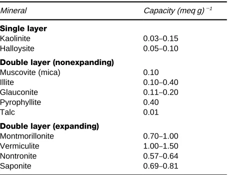
Table 3 Examples of the cation exchange capacities of some clay minerals
Mineral Capacity (meq g)\1 Single layer
Kaolinite 0.03}0.15 Halloysite 0.05}0.10
Double layer (nonexpanding)
Muscovite (mica) 0.10 Illite 0.10}0.40 Glauconite 0.11}0.20 Pyrophyllite 0.40 Talc 0.01
Double layer (expanding)
Montmorillonite 0.70}1.00 Vermiculite 1.00}1.50 Nontronite 0.57}0.64 Saponite 0.69}0.81
environments. The presence of [FeO4]5\entities
con-fers a negative charge on the silica layers, which can then be compensated by exchangeable cations sited between the layers.
Whatever the mechanisms whereby cations are ac-commodated into single-layer clays, their exchange capacities are low. The minerals can also exhibit a low anion capacity via labile hydroxyl groups.
In double-layered clays the element of structure is that of two sheets of tetrahedra separated by cations. The unexpandable double layer aluminosilicates, like the micas, have isomorphous substitution of alumi-nium for silicon in the double layers. This creates strong ionic bonding between the negatively charged layers and the interlayer cations. The cations are in an environment virtually water free so ion exchange is difRcult, and conRrmed mainly to defect and edge effects. The micas, and similar minerals, are examples of exchangers where the potential cation ion ex-change capacity, expected from their stoichiometry, is not experimentally achieved. The need for the con-cept of loading is thereby illustrated.
In the expandable double-layered silicates hydrated cations are held in interlayer positions by weak elec-trostatic forces between their hydration shells and the silica sheets. Some isomorphous substitution in the tetrahedral layers is present but does not have a major effect on ion exchange behaviour. The loosely held cations are readily exchanged, and the interlayer distance changes as a function of hydrated cation size. Further ingress of solvent is easy. More water, or even organic molecules such as glycols, can penetrate the layers to further swell the structure. Montmorillo-nites are typical expanding double-layered clays. Examples of cation capacities for the clay minerals are listed inTable 3.
The ability of clays to act as exchangers is, of course, a major property of soils related to their ability to sustain plant nutrients. Incorporation of metals, such as copper and nickel, aids their use as catalysts. Their use as ion exchangers seems to be limited to wastewater treatment by glauconite (green sand), sometimes in manganese form, and often er-roneously described as a zeolite.
Zeolites In these aluminosilicate minerals the con-stituent [SiO4]4\ and [AlO4]5\ share all corners to
create a three-dimensional framework structure car-rying a negative charge. This framework charge is balanced by the presence of cations contained in channels and cavities within the framework. Many zeolites are able to contain a large amount of water in these cavities and channels, which can have void volumes as high as 50% of their total volume. They are known both as natural species and as synthetic
minerals capable of being manufactured on the tonnes scale.
Nearly 100 different frameworks have been crystallographically deRned for zeolites, and related structures, each one having a unique molecular archi-tecture. The internal dimensions of their channels and cavities are close to molecular dimensions and this has led to their employment as ‘molecular sieves’ and catalysts. Usually synthetic zeolites perform these functions and thereby make an incalculable contribu-tion to the world economy, particularly in the oil industry. Examples of zeolite structures are provided inFigures 11and12.
Most zeolites readily exchange the cations from their voids. This facile process is vital to their utility as both molecular sieves and catalysts, and has been responsible for most of the literature describing their cation exchange properties. Because detailed crystal-lographic data is available for some zeolites (even including the positions of water molecules within their frameworks), they have been used to model theories of ion exchange kinetics and equilibria.
These minerals can exhibit very high selectivities, with high capacities, and have been extensively studied for use as such, while being restricted by their instability in acid environments. Examples where use can be made of cation exchange properties will be considered in a later section.
Figure 11 Linkage of Si, AlO4tetrahedra to form a chain struc-ture that, when joined in three dimensions, forms the framework of the zeolite natrolite.
Figure 12 Structure of (A) synthetic zeolite A and (B)
syn-thetic faujasite (zeolites X and Y) showing the internal cavities of molecular dimension. (Each line represents an oxygen and each junction a silicon or aluminium.)
pass through the restricting dimensions in the chan-nels. These effects contribute to the ‘ion-sieve’ effects noted in some zeolites.
Other framework structures Earlier the point was made that adherence to the traditional classiRcations of inorganic ion exchangers was not entirely appro-priate. This has arisen for a number of reasons, a ma-jor one being the endless search for novel catalysts. The synthetic routes chosen frequently mimic those of zeolite synthesis with the aim to produce robust framework structures based on the assemblage of coordination polyhedra. Implicit in this is the likeli-hood that a microporous medium possessing ion ex-change properties will result. To date very little atten-tion has been given to the numerous substances appearing from this source in the context of ion exchange, so only a brief survey will be given.
Prominent in the novel frameworks produced by assemblage of tetrahedral units has been the incor-poration of [TO4] units into zeolite-like structures.
Numerous varieties with T"P, B, Co, Cu, Zn, Mn, Mg, Ga, Ge, Be have been identiRed, and some have also been found in nature. The possibility has already been claimed that a new family of anion exchangers can be made with a framework in which an excess of [PO4]5\over [Si, AlO4]n\tetrahedra prevails,
render-ing the framework positively charged.
Discoveries like these have prompted a reassess-ment of the opportunities to make inorganic
‘molecu-larly ordered solids’ (MOS) based on well-understood coordination polyhedra (tetrahedral and octahedral) formed by metals such as Ti, As, Zr, Hf, Nb, Mo, W, V, etc. They will prove a fruitful area in which to pursue the search for selective exchangers.
Other layer structures
Pillared materials Mention has already been made of the exchange of organic molecules into clays and layered phosphates/phosphites. Similar expansions can arise when a large inorganic ion is introduced between the layers. An early example of this was the exchange of a ‘Keegin’ ion, such as [Al13O4(OH)24]7#,
[image:14.568.305.501.246.659.2]Table 4 The cation exchange capacities of some zeolite min-erals
Zeolite Capacity (meq g\1) Natural
Analcime 4.95 Chabazite 4.95 Phillipsite 4.67 Clinoptilolite 2.64 Mordenite 2.62
Synthetic
A 4.95
X 6.34
Y 4.10
an alumina pillar propping open the layers to 1}2 nm. Again, the intention of this work was to develop wide-pored cracking catalysts. When ion exchange capacities were measured they proved to be orders of magnitude greater than the equivalent amount of alumina. No signiRcant residual capacity arising from the clay was detected. Many similar pillared substan-ces have now been made with a variety of differ-ent layered compounds (natural and synthetic) and inorganic pillars. Little is known of their ion ex-change properties.
Hydrotalcites The natural mineral, hydrotalcite, is a layered compound of composition Mg6Al2(Co3)
(OH)16)4H2O. Synthetic analogues can be obtained
with other metals replacing magnesium and alumi-nium (Co, Ni, Fe for example). They are commercial-ly available as anion exchangers.
Uses of Ion Exchange Materials
Resins
Water treatment The annual production of ion ex-change resins has been estimated at 500 000 m3, of
which at least 90% goes to industrial water treat-ment. The various end uses in this area will now be described.
Softening The removal of calcium and magnesium ions from water supplies is a requirement for many industries. Laundries, dye-houses and cleansing plants are examples of speciRc industries but the need can be generalized to many hot water circuits, heat exchangers and low pressure boilers. Strong sulfonate styrene gel cation resins, in sodium form with 8}12% cross-linking, are the usual choice, but macroporous resins may well be used when the process is demand-ing in terms of attrition, elevated temperatures or in the presence of oxidizing agents. An example of such
an aggressive environment is in the modern Chlor-Alkali membrane electrolysis cell for the production of chlorine gas and sodium hydroxide. This process also provides an example of the use of a chelating style resin (iminodiacetate, or aminophosphinate) to scavenge alkaline earth ions (see Table 1).
Dealkalization In dealkalization, weakly acidic car-boxylic resins, in hydrogen form, are used to meet the limits of calcium and magnesium concentrations needed in feed water to medium pressure boilers. Hydrogen ions released are neutralized by the HCO\3
and CO2\
3 anions present to give carbon dioxide,
which remains in solution as carbonic acid. The sof-tening is only partial and sometimes a sodium resin treatment, as above, is added. There may be an ancil-lary need to attain some demineralization as well which would involve an additional column treatment. Single-stage dealkalization Rnds wide application in the treatment of cooling water and water used in the food and drinks industries. Desalination is a deal-kalization process. Modern plants use membranes made from ion exchange resins in an electrodialysis cell.
Demineralization Demineralization involves the use of both cation and anion resins to produce ‘de-ionized water’. This can be achieved by a two-stage process in which the raw water isRrst passed through a column containing a strong cation resin (H) form, and then through a strong anion resin (Type I or II). Some ion exchange plants use weak anion resins, and multistage processes or countercurrent variants are available as standard plant.
general aim to inhibit corrosion. The nuclear power industry constantly strives to reduce potential cor-rosion in its steam/water circuits. In pressurized water reactors with ‘recirculating steam generators’ some operators have a target of low ng levels of ionic impurities per kg water used. These reactors use addi-tions to the primary coolant of (a) boric acid to help moderate the Rssion process and control corrosion and (b) lithium hydroxide, also to inhibit corrosion. They depend on a sophisticated use of resin beds to achieve the desired coolant water chemistry. In the semiconductor manufacturing industry the demands for ‘ultra pure’ water are even more stringent with targets in the range pg kg\1. (Note ‘ultra pure water’
is usually taken to mean water with less than g kg\1.) Water used in the production of
pharma-ceuticals also involves the use of high purity water. In both dealkalization and demineralization the choice between a gel or macroporous resin is again conditioned by the relative aggressiveness of the feed. In some instances additional factors such as high column pressure differentials and the need for fast kinetics will lead to the use of macroporous materials. Additional treatment of demineralized water with a sulRte-based exchanger removes oxygen via the following route:
2R2SO3#(O2)aq"2R2SO4
Removal of organics In this context ‘organic’ means the complex anions arising from decay products of organic matter and peaty soils. They are mainly deriv-atives of fulvic and humic acids and can be removed by employment of a macroporous strong anion resin. This was one of the main uses envisaged from the development of resins of this type. Typical waters requiring treatment contain a total organic carbon (TOC) of 2}20 mg of carbon per litre, which can be more than halved by resin exchange.
Nitrate removal The presence of nitrates in water intended as a potable supply, or for the food industry, is a major environmental concern, arising from the use of nitrate fertilizers. The suggested limit is 50 mg NO\3 L\1, and the options open to attain this include
microbiological, reverse electrodialysis using nitrate selective membranes, and traditional ion exchange methods.
Ion exchange is the cheapest and most reliable approach, not least because of the wealth of experi-ence and established technology available. It makes use of nitrate-selective resins based on triethylam-monium as functional groups. It is thought that the selectivity may arise from a size/shape exclusion ef-fect that encourages the uptake of the small, Sat,
nitrate anion in preference to the larger sulfate, and perhaps chloride, ions, with their spherical nature also being a factor.
Waste efWuent treatment Prevention of the re-lease into the environment of toxic metals arising from industrial processes has long been a useful ap-plication of ion exchange. Typical examples come in the metalRnishing industries whereby wash solutions containing chromium and zinc, for example, can be rendered suitable for discharge. Many similar exam-ples can be found in the photographic, paper and metal pickling industries. Some progress has been made in the employment of resins in the recovery of water from sewage treatment plants.
Another area of concern is in the treatment of aqueous nuclear wastes. The use of ion exchange offers the prospect of vastly reducing some prob-lems by volume minimization of the waste form. Resins have high capacities for the trace quantities of hazardous isotopes arising from nuclear fuel produc-tion, reprocessing, reactor water circuits, decommis-sioning, and in ‘pond’ waters. The latter can be used as a major example where ion exchange materials can be used to scavenge the caesium and strontium radio-isotopes that leak into the ponds in which spent fuel rods are stored prior to decladding and reprocessing (see Table 1).
In all nuclear applications the ultimate safe storage of the waste form is of prime importance. Previous practice has often been to store the highly radioactive resins in a concrete pit. Clearly this is undesirable, due to the limited radiation stability of the organic resins, and new approaches are now preferred, either by using inorganic exchangers or by encapsulating the spent resins in concrete. Even encapsulation should be regarded as temporary in the timescales recommended for nuclear waste disposal. The search for suitable inorganic materials has only been realized in a limited area because of reasons that will be considered later. The resin manufacturers are contin-uing to synthesize nuclear resins, and seek to provide products that can take up radioisotopes with high degrees of selectivity, often by chelating action. An example of this area of work is in the potential use of novel strong base polyvinylpyridine anion resins to remove americium and technetium from nuclear wastes.
Table 5 Metals recovered and purified by ion exchange Uranium
Thorium Rare earths
Plutonium (and other trans-uranics such as neptunium and americium)
Gold Silver
Platinum metals Copper Cobalt Nickel Zinc Chromium Rhenium Molybdenum
mineral dumps. Ion exchange competes with liquid}liquid extraction in these areas, with varying success, and can be used in combination with this process in some instances. Macroporous resins are popular for these applications.Table 5provides a list of metals that can be recovered on a commercial basis by ion exchange.
Note should be made of the essential role played by resins in aiding the separation of uranium from its ore in nuclear fuel production, whereby uranyl sulfate is loaded onto anion resins from which it is leached prior to solvent extraction to complete the separation process. Solvent extraction is the major separation technique in the process and the same is true of reprocessing, but both anion and cation resins are an essential part of the method whereby puriRed ura-nium and plutoura-nium are obtained.
Other applications of ion exchange resins The reader is reminded of the wide use of resins in cataly-sis, and in the puriRcation of antibiotics, vitamins, nucleotides, amino acids, proteins, enzymes and vi-ruses that have been excluded from this review. One application in the puriRcation of natural substances is the use of aRnely sized cation resin to replace sodium and potassium ions by magnesium in sugar reRning. Sodium and potassium promote the deleterious formation of molasses that has to be discarded.
Historically the best studied area of ion exchange application has been the use of exchange materials to perform separations to aid quantitative analysis. Ori-ginally, in the majority of cases the intent was either to remove interfering ions or to scavenge trace ions onto an exchanger so as to preconcentrate sufR -cient material for analysis. This work forms the basis of ion exchange chromatography, which has evolved into one of the most useful analytical techniques ever developed, namely high performance ion chromato-graphy (HPIC). In HPIC low capacity ion exchange
materials are used in pellicular form on stable micro-spheres. Fast uptake of trace quantities of ions is guaranteed and differential elution provides an adequate separation so that individual ions can be recognized by their diagnostic column residence times. This presupposes that a suitable detector can monitor the column efSuent to detect the ions in the eluent. Conductivity changes prove to be ad-equate for most purposes.
An important stage in the development of the tech-nique was the use of suppressor columns that were able to remove the ions present as a consequence of the use of eluents by retaining them on suitable resins, thus greatly improving the detection sensitivity. Highly sophisticated instruments are now able to revolutionize the quantitative trace analysis of ca-tions and anions, both organic and inorganic. The method is highly reproducible, rapid, and able to carry out routine analyses on a diverse range of analytes.
Inorganic Exchangers
Inorganic materials offer the possible advantages of increased thermal, and radiation, stability over their resin counterparts. In some cases, e.g. the zeolites, they can also compete in terms of capacity and in extremely selectivity exchange. These advant-ages have created great interest in their potential use for aqueous nuclear waste treatment. This is encouraged by the preferences stated by regulatory bodies that inorganic exchangers are preferred for incorporation into the accepted waste disposal forms for medium and intermediate level radioactive waste. The main problems, some of which have been men-tioned earlier, encountered in progress towards this ideal are:
1. the inherent difRculties in developing reliable characterization methods for many amorphous exchangers;
2. the fact that synthesis often results in products with small particle sizes inappropriate to column use;
3. the lack of materials compatible with direct treatment of the acid streams common in, for instance, reprocessing plants, and even the high pH (&11.4) encountered in fuel storage ponds; 4. the liability to hydrolytic damage, even under
modest pH conditions.
Waste efWuent treatment
Nuclear waste Reference has already been made to the earlier use of AMP and zirconium phosphate to scavenge Cs and Sr radio isotopes from nuclear waste streams. Other earlier processes made use of clays, green sand, and amorphous aluminoscilicates. These latter materials, marketed as ‘Zerolites’, resembled the early ‘permutites’. The zeolite minerals also were early candidates for use, but often resins took prefer-ence until the increased environmental considerations related to the safe disposal of highly active resins became of concern.
Initially studies in the US nuclear industry showed that the natural zeolites chabazite, mordenite and clinoptilolite had high selectivities for strontium and caesium Rssion isotopes, and these have been de-veloped into modern plants. Examples of these are the use of clinoptilolite in the SIXEP process at BNF, SellaReld, UK, and chabazite at Oak Ridge, USA. A mixture of synthetic zeolite A and chabazite was the main agency used to scavenge caesium after the Three Mile Island accident, and clinoptilolite was extensively used at Chernobyl. Mention should be made of the use of clinoptilolite to reduce the body burden of Rssion isotopes in living hosts (including humans), and to reduce their presence in crops.
Work in progress on the treatment of high level waste (HLW) to encapsulate a wide range of isotopes, including-emitters, includes tests on composite ex-changers based on inorganic materials in polyacrylic resins. Considered also are ferrocyanides and silicotitanates with framework structures. Zeolites, zirconium phosphate and AMP have been used to obtain pure isotopes for commercial purposes.
Wastewater treatment The ubiquitous occurrence of clinoptilolite on the Earth’s surface has created numerous publications describing its use to treat water from sewage plants. Several plants have been construc-ted to this end, e.g. Denver and Rosemount, USA and Budapest, Hungary. These make use of local supplies, and regeneration steps have been developed. Other areas of the world pursuing this application include Italy, Cuba, Japan and several locations in Eastern Europe. Eastern Europe has also been the major source of literature describing the employment of clino-ptilolite to remove toxic metals from efSuent streams. In these cases regeneration is not usually an option, that is the processes are ‘once-through’. Recently clinoptilolite has been widely used to treat swimming pool water in circulatory systems, with regeneration.
Other areas
Detergency The need to remove hardness from washing water has long meant that a softener
(‘buil-der’) has been a vital component of commercial deter-gents. Within the last 10}15 years there has been a move away from the phosphate builders tradition-ally used. The main agencies chosen to replace them have been synthetic zeolites. Currently the world an-nual production of synthetic zeolites for this purpose is approaching 1 million tonnes. This is largely as zeolite A, but a synthetic gismondine, zeolite MAP, is an alternative. Zeolites can be incorporated into both powder and liquid detergents, and natural zeolites have been used in cheaper powders.
Dialysis Amorphous zirconium phosphate is used in portable renal dialysis equipment. To remove urea from the dialysate it isRrst converted to ammonium carbonate by the enzyme urease. The ammonium ion is then taken up by ZrP. In some systems hydrous zirconia has been used to sorb phosphate ions re-leased from the ZrP by hydrolysis.
Further Reading
ClearReld A (1982) Inorganic Ion Exchange Materials. Boca Raton, FL: CRC Press.
Dyer A, Hudson MJ and Williams PA (eds) (1993)Ion Exchange Processes:Advances and Applications. Cam-bridge: Royal Society of Chemistry.
Dyer A, Hudson MJ and Williams PA (eds) (1997)Progress in Ion Exchange: Advances and Applications. Cam-bridge: Royal Society of Chemistry.
Harland CE (1994)Ion Exchange: Theory and Practice, 2nd edn. Cambridge, UK: Royal Society of Chemistry. Helfferich F (1962)Ion Exchange. New York: McGraw-Hill. IAEA (1967)Operation and Control of Ion Exchange Pro-cesses for the Treatment of Radioactive Wastes, Tech-nical Report Series no. 78. Vienna: IAEA.
Marinsky JA and Marcus Y (eds) (1995)Ion Exchange and Solvent Extraction, vol.12. New York: Marcel Dekker (and earlier volumes in this series).
Naden D and Streat M (eds) (1984)Ion Exchange Tech-nology. Chichester: Ellis Horwood.
Qureshi M and Varshney KG (1991)Inorganic Ion Ex-changers in Chemical Analysis. Boca Raton, FL: CRC Press.
Slater MJ (ed.) (1992)Ion Exchange Advances. London: Elsevier Applied Science.
Streat M (ed.) (1988)Ion Exchange for Industry. Chiches-ter: Ellis Horwood.
Tsitsishvili GV, Andronikashvili TG, Kirov GN and Filizova LD (1992)Natural Zeolites. Chichester: Ellis Horwood. Williams PA and Hudson MJ (eds) (1987)Recent Develop-ments in Ion Exchange. London: Elsevier Applied Science.
Williams PA and Hudson MJ (eds) (1990)Recent Develop-ments in Ion Exchange-2. London: Elsevier Applied Science.