Turbo Detection of Space-time Trellis-Coded Constant Bit Rate
Vector-Quantised Videophone System using Reversible Variable-Length Codes,
Convolutional Codes and Turbo Codes
B. L. Yeap, R. G. Maunder, S. X. Ng, and L. Hanzo
School of ECS, University of Southampton, SO17 1BJ, UK.
Tel: +44-23-8059 3125, Fax: +44-23-8059 4508
Email:
{
bly,rm02r,sxn,lh
}
@ecs.soton.ac.uk, http://www-mobile.ecs.soton.ac.uk
Abstract
In this treatise we characterise the achievable performance of a proprietary video transmission system, which employs a Constant Bit Rate (CBR) video codec that is concatenated with one of of three error correction codecs, namely a Re-versible Variable-Length Code (RVLC), a Convolutional Code (CC) or a convolutional-based Turbo Code (TC). In our in-vestigations, the CBR video codec was invoked in conjunc-tion with Space-Time Trellis Coding (STTC) designed for transmission over a dispersive Rayleigh fading channel. At the receiver, the channel equaliser, the STTC decoder and the RVLC, CC or TC decoder, as appropriate, employ the Max-Log Maximum A-Posteriori (MAP) algorithm and their oper-ations are performed in an iterative ‘turbo-detection’ fashion. The systems were designed for maintaining similar error-free video reconstruction qualities, which were found to be sub-jectively pleasing at a Peak Signal to Noise Ratio (PSNR) of 30.6 dB, at a similar decoding complexity per decoding iteration. These design criteria were achieved by employ-ing differemploy-ing transmission rates, with the CC- and TC-based systems having a 22% higher bandwidth requirement. The results demonstrated that the TC-, RVLC- and CC-based sys-tems achieve acceptable subjective reconstructed video qual-ity associated with an average PSNR in excess of 30 dB for
Eb/N0values above 4.6 dB, 6.4 dB and 7.7 dB, respectively.
The design choice between the TC- and RVLC-based sys-tems constitutes a trade-off between the increased error re-silience of the TC-based scheme and the reduced bandwidth requirement of the RVLC-based scheme.
1. INTRODUCTION
In this contribution, we analyse and characterise the achiev-able performance of a proprietary Constant Bit Rate (CBR) video codec in the context of Space-Time Trellis Coded (ST-TC) systems [1]. The motivation for employing a CBR video codec is that of system design convenience, since CBR sys-tems, such as the second-generation GSM system, exhibit a low complexity as a consequence of requiring no statistical multiplexing. Furthermore, the proposed CBR systems ex-hibit a low latency equal to the duration of each video frame,
The financial support of both the EPSRC, Swindon UK and the EU under the auspices of the Phoenix project is gratefully acknowledged.
which was 100ms, facilitating lip-synchronisation. Addition-ally, the CBR design philosophy allows video frame syn-chronisation to be readily re-established in the presence of transmission errors. For the sake of comparison, we have in-voked three different error-resilience codecs at the output of the CBR videophone scheme, namely a Reversible Variable-Length Code (RVLC) [2], a rateRcc = 34 constraint length
K = 5Convolutional Code (CC) and anRtc = 34 K = 4 convolutional-based Turbo Code (TC) [3]. These values of
K were chosen for the sake of having similar complexities per decoding iteration amongst the three systems. Specifi-cally, symmetrical RVLCs were utilised in the RVLC-protect-ed scheme, since they may be designRVLC-protect-ed for a free distance of two and they also represent a good compromise between coding rate and error resilience. We also considered CCs since they are known to yield good performance despite hav-ing short codhav-ing block lengths, while TCs, are capable of approaching the Shannonian limit.
In order to improve the achievable videophone link qual-ity and to approach the capacqual-ity of the CBR videophone sch-eme, we propose systems that amalgamate STTC with the stated RVLC, TC and CC codecs. A STTC scheme has been invoked for providing additional diversity gains as well as for overcoming the limited capacity offered by hostile wire-less channels [4]. STTC relies on the joint design of channel coding, modulation, transmit diversity and on the associated optional receiver diversity schemes. Rather than performing the channel equalisation, STTC decoding and consecutive source decoding operations separately, the proposed system performs these operations iteratively, exchanging soft infor-mation amongst them and yielding a performance improve-ment. This philosophy is based on that of turbo equalisa-tion [5], which was first employed in a convoluequalisa-tional encoded BPSK system transmitting over dispersive channels. In or-der to reduce the complexity of the turbo detector, we have employed the In-phase/Quadrature-phase (I/Q) turbo detec-tor proposed in [4, 6].
2. SYSTEM OVERVIEW
We commence by describing the proprietary CBR video co-dec and the RVLC coco-dec employed in the first of the three candidate videophone system, illustrated in Figure 1. The coding philosophy of this Vector-Quantised (VQ) scheme was described in [7, Chapter 13], which was designed for the en-coding of(176×144)-pixel greyscale Quarter Common In-termediate Format (QCIF) head-and-shoulder video sequen-ces.
EncoderVideo Frame
Intra-EncoderVideo Inter-Frame
u Frame Size Analyzer
u
Na
Nb
b1
b2
b3
b5
b4
A
B
w
wb
wa
a1
a2
Concat
Concat
FLC FLC
FLC
FLC
FLC FLC
FLC
[image:2.595.56.288.161.286.2]Packetiser v RVLC
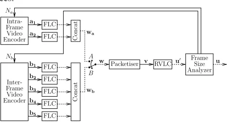
Figure 1: The proprietary CBR video encoder employing RVLC encoding. Solid lines indicate a transfer of symbols, while dashed lines indicate a transfer of bit strings.
In this system, each CBR coded video frame consists of 2048 bits, which completely fill five transmission frames, as will be described below. In Section 3, it is shown that this bit allocation permits the reconstruction of the ‘Lab’ video sequence [7] with a pleasing subjective reconstruction qual-ity in the error-free case. At the 10 frames/sec video frame scanning rate employed, the resultant transmission bitrate is 20.48 kbps.
The proprietary video encoder [7, Chapter 13] incorpo-rates both an intra- and an inter-frame encoder, as shown in Figure 1. Inter-frame encoding achieves a high level of compression by encoding the Motion Compensated Error Residual (MCER) between the current and previous frames. Partial Forced Update (PFU) [7, Section 12.8], Motion Com-pensation (MC) [7, Section 12.2] and Vector Quantisation (VQ) [7, Section 13.3] are employed. The Inter-frame en-coding process operates on(8×8)-pixel blocks. There are 396 of these blocks in each(176×144)-pixel QCIF frame. The PFU, MC and VQ operations are applied only to a lim-ited number of so-calledactive blocksin each frame. There are 22 PFU- and 63 MC-active blocks in each video frame, whilst the number of VQ-active blocks is variable and con-trolled by the ‘Frame Size Analyzer’ feedback parameterNb, as shown in Figure 1. The specific selection of PFU-active blocks in each video frame is predetermined, while the spe-cific choice of the MC- and VQ-active blocks is performed on a frame-by-frame basis using gain-cost control [7, Section 12.6].
The average luminances of PFU-active blocks are quan-tized and conveyed to the remote decoding using the PFU symbol seta1. They are used for mitigating the channel in-duced video degradation in the reconstruction of the previous video frame, which would otherwise persist during the
recon-struction of the current inter-frame coded video frame. The motion vector symbolsb2are conveyed to the decoder for the set of MC-active blocks. Similarly, the VQ codebook en-try symbolsb3are generated for the set of VQ-active blocks for the sake of representing the corresponding MCERs. The positions of PFU-active blocks are predetermined and known to the decoder. By contrast, the positions of each MC- and VQ-active block must be optimised and conveyed explicitly on a video frame-by-frame basis. A structured ordering of the MC- and VQ-active block indices is employed for the sake of signalling the active block positions b4 to the de-coder. The structured ordering employed allows the detec-tion of errors within the received active block indices. The value ofNbis conveyed using the symbolsb5of Figure 1.
However, inter-frame encoding is unable to represent the first frame of a video sequence, since there is no available previous frame to allow the generation of the MCER in this case. For this reason, intra-frame encodingmust be em-ployed for representing the first video frame of a sequence in isolation. The video frame is divided into a grid of(Na×Na) perfectly tiling blocks, whereNais a feedback parameter, as shown in Figure 1. The average luminances of the blocks are quantised and conveyed using the intra-frame coding sym-bol set, a1, [7, Section 12.5]. The specific value ofNa is conveyed to the decoder using the symbolsa2of Figure 1.
During intra- and inter-frame encoding, two [a1. . .a2] and five[b1. . .b5]symbol sets are generated, respectively. As described above, the symbol set sizes are governed by the values of the parametersNaandNb, respectively. These val-ues are provided by the system’s ‘Frame Size Analyzer’ and bitrate control feedback mechanism, as shown in Figure 1. The employment of the above mechanism allows the gener-ation of CBR encoded video framesu, which efficiently use the 2048 bits that are available for their representation.
Bit-string representations of the symbols[a1. . .a2]and
[b1. . .b5] are generated by applying Fixed Length Codes (FLC’s). The allocation of FLCs to particular symbol values is based on their probability of occurrence. These bit strings are concatenated for the sake of forming the bit-stringswa andwb, respectively, as seen in Figure 1.
A selection betweenwa andwb is made depending on whether the current video frame is to be intra- or inter-frame encoded. The selected concatenated bit string,w, is packe-tised using a 4-bit packetiser, in order to form a set of 4-bit video symbolsv, as portrayed in Figure 1.
Due to the allocation of FLCs based on their probabilities of occurrence, these symbols have a reduced entropy, allow-ing an RVLC havallow-ing a high codallow-ing rate to be designed. The RVLC employed consists of 16 possible codewords{00, 101, 0110, 1111, 010, 01110, 011110, 0111110, 1001, 11011, 100001, 110011, 10001, 1100011, 1000001, 1110111}. The-se were The-selected baThe-sed on the probability of occurrence of the 16 possible values of video symbols inv, as observed for the training video sequence set, and to give a free distance of two.
found to be 1897 coded video bits. The corresponding aver-age RVLC rate is thereforeRvlc= 18972048 = 0.926.
CC/TC Encoder
b2 b3 b4
wa
wb
Concatenate
A
B
w a1
EncoderVideo Frame
Intra-EncoderVideo Inter-Frame
FLC
b1 FLC
FLC
FLC
FLC
[image:3.595.77.268.81.188.2]u
Figure 2: The proprietary CBR video encoder, which is concatenated with a convolutional codec or a convolutional-based turbo codec. Solid lines indicate a transfer of symbols, while dashed lines indicate a transfer of bit strings.
CC TC
G0: 1 1 0 G0: 1 0 0 0 0 0 G1: 1 0 1 G1: 0 0 1 0 0 0
1 =transmitted bit
0 =non transmitted bit
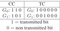
Table 1: Puncturing pattern applied to the coded bits of the
Rcc = 12CC andRtc= 13 TC in order to obtain a code rate
of 34for the CC and TC, respectively.
In the second and third of the three candidate CBR video-phone schemes, CC or TC codecs are employed instead of the RVLC codec for the sake of investigating whether they are capable of providing an improved error resilience. Un-like the RVLC, these codecs employ a fixed coding rate of
Rcc =Rtc = 34. In order to obtainRcc = 34 convolutional codes, we have employed the puncturing pattern used by Ya-suda et al. [8]. For the sake of arriving at Rtc = 34 TC, we have applied regular puncturing to the turbo codes. This puncturing pattern has been determined experimentally. For procedures on designing optimum high rate turbo codes via puncturing, the interested reader is referred to [9]. These puncturing patterns are summarised in Table 1.
Since in these systems a fixed coding rate of 34 is em-ployed, there is no uncertainty about the length ofwrequired to giveuhaving the desired length. Therefore, fixed values ofNaandNbare employed. For this reason, the ‘Frame Size Analyzer’ and feedback mechanisms of Figure 1 are unnec-essary in the specific scheme used here. This simplified video encoder is depicted in Figure 2. Note that sinceNaandNb are fixed, there is no need to convey their specific values to the decoder and hence the symbol sets a2 andb5 are not generated by the video encoder used. Each encoded video framewis represented by 1876 bits, giving a similar recon-struction quality to that of the RVLC-protected scheme. The
3
4-rate code is invoked for generatingu having a length of
2502 bits.
For the RVLC protected system, u is interleaved by a 2048-bit channel interleaverπcand subsequently directed to
aTx = 2-transmitter,n = 4-state andM = 4-PSK STTC encoder. For the sake of employing the same interleaver length and allowing a fair comparison to be made, the 2502-bit stringsuof the CC- and TC-based schemes are concate-nated and divided into 2048-bit partitions, before interleav-ing.
s
s TX1
TX2 c
π
π π Space−time
trellis encoder
Turbo detector CBR Video Codec
[image:3.595.304.537.125.193.2]using RVLC/CC/TC
Figure 3: Schematic of the RVLC/CC/TC-coded and con-catenated space-time trellis coded CBR video system em-ploying turbo detection at the receiver. The notations πc
andπsrepresent the channel interleaver and space-time trel-lis coding interleaver, respectively.
At the output of the STTC encoder, the encoded symbols are interleaved by a 1025-symbol random STTC interleaver represented byπsin Figure 3. Note that random interleavers are utilised for both the bit-based channel interleaver and for the symbol-based STTC interleaver. As mentioned before, the same interleaving rule is used for all transmit antennas in order to preserve the rank property of the STTCs [1]. The 1025 STTC-deinterleaved symbols are mapped to five trans-mission frames each, having 205 data symbols.
Additionally, a dispersive two-path Rayleigh fading chan-nel having equal symbol-spaced tap weights was used. The Rayleigh fading statistics obeyed a normalised Doppler fre-quency of10−5, where the fading magnitude and phase was kept constant for the duration of a transmission burst. At the receiver, the channel impulse response was assumed to be perfectly estimated.
[image:3.595.114.232.263.324.2]0 1 2 3 4 5 6 7 8 9 10 11 12
E
b/N
0[dB]
100
10-1
10-2
10-3
10-4
10-5
10-6
BER
[image:4.595.59.258.67.231.2]TC K=4 CC K=5 RVLC Max Itr Itr 1
Figure 4: BER performance of the RVLC-, CC- and TC-coded STTC CBR videophone systems communicating over a dispersive two-path equal-power and symbol-spaced wide-band Rayleigh fading channel, when employing turbo detec-tion at the receiver. The term ‘Max Itr’ is used for indicating the number of turbo detection iterations that have to be per-formed such that no substantial further iteration gains were achieved using additional iterations. In the case of the RVLC, CC and TC schemes, this was three, four and four, respec-tively.
3. RESULTS AND DISCUSSION
Having described the turbo-detected videophone transceiver, let us now consider its performance. This was characterised using 20 repetitions of the 100-frame Lab video sequence’s transmission in each simulation. The ‘head-and-shoulders’ Lab video sequence exhibits a moderate level of motion ac-tivity and it was not used in the video codec’s training set.
As will be shown later, the number of turbo detection it-erations that had to be performed such that no substantial fur-ther iteration gains were achieved using additional iterations, for the RVLC, CC and TC schemes was three, four and four respectively. The Bit Error Ratio (BER) performance after these numbers of decoding iterations was compared to that after a single decoding iteration, as shown in Figure 4. The latter scenario is equivalent to performing channel equalisa-tion, STTC decoding and RVLC decoding separately.
TheEb/N0measure is employed in Figure 4 to compen-sate for the differing system throughputs and is defined as:
Eb
N0 = 10 log
1
R×log2(M)
+SNR, (1)
where R = Rvlc, Rcc andRtcfor the RVLC, CC and TC protected systems, respectively. Additionally, for 4PSK, we haveM = 4.
After the above-mentioned number of turbo detection it-erations, similar gains of approximately 5.5 dB, 6 dB and 5 dB were achieved by performing iterative decoding at a BER of10−3 for the RVLC-, CC- and TC-based systems, respectively.
At a BER of10−3and after the stated number of decod-ing iterations, the TC system (requirdecod-ing anEb/N0of 3.6 dB) outperforms the RVLC system (requiring anEb/N0of 4 dB) by 0.4 dB, which in turn outperforms the CC system (requir-ing anEb/N0of 7.8 dB) by 3.8 dB. Although the TC system using four decoding iterations outperforms the RVLC sys-tem employing three decoding iterations, this is achieved at a 33% higher complexity and a 22% higher bandwidth require-ment. This is becauseuhas a length of 2502 bits compared to the RVLC system’s vector length of 2048 bits.
Figure 5 shows the variation of the ‘Lab’ sequence’s ob-jective reconstruction quality as a function of Eb/N0 after various numbers of turbo detection iterations. The measure of objective video reconstruction quality was the average Peak Signal to Noise Ratio (PSNR) [7, Equation 12.8]. Each aver-age PSNR value was calculated across the 20 repetitions of frames 26 to 100 of the Lab sequence’s reconstruction. These frames were generated during the video codec’s steady-state response following the codec’s initial ‘warm-up’ phase, dur-ing which the relatively poor reconstruction quality of the intra-frame coded first video frame is gradually improved.
0 2 4 6 8 10 12 14
E
b/N
0[dB]
2022 24 26 28 30 32
PSNR[dB]
TC K=4 CC K=5 RVLC Max Itr Itr 1
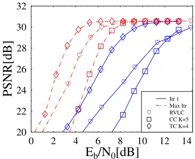
Figure 5: Variation of the Lab sequence’s objective video reconstruction quality versusEb/N0after various numbers of turbo detection iterations.
For high values ofEb/N0, perfect error-free reconstruc-tions of the ‘Lab’ sequence were obtained. These were asso-ciated with a PSNR of 30.6 dB and had a pleasing subjective reconstruction quality. With the subjective analysis of the reconstructed video sequences, acceptable video quality as-sociated with no annoying virtual artifacts was obtained for PSNR values in excess of 30 dB. After the above-mentioned number of turbo detection iterations, gains of approximately 8 dB, 6 dB and 5 dB were achieved by performing iterative decoding at a PSNR of 30 dB for the RVLC-, CC- and TC-based systems, respectively.
At a PSNR of 30 dB and after the stated number of decod-ing iterations, the TC system (requirdecod-ing anEb/N0of 4.6 dB) outperforms the RVLC system (requiring anEb/N0of 6.4 dB) by 1.8 dB, which outperforms the CC system (requiring an
[image:4.595.307.504.323.484.2]system using four decoding iterations outperforms the RVLC system employing three decoding iterations, this is achieved at a higher complexity and bandwidth requirement. For lower
Eb/N0values the subjective video reconstruction quality was seen to rapidly deteriorate.
1 2 3 4 5 6
Number of Iterations 2
4 6 8 10 12 14 16
Eb
/N
0
to
achieve
PSNR=30dB
[image:5.595.64.259.137.290.2]TC K=4 CC K=5 RVLC
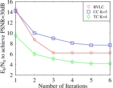
Figure 6: TheEb/N0ratio required at PSNR= 30dB by the different complexity turbo detectors characterised in terms of the number of decoding iterations.
In Figure 6 we compare the relative performance of the three considered schemes at equal system complexities. Fig-ure 6 depicts theEb/N0value required by the RVLC-, TC-and CC-based videophone systems, in order to achieve a PSNR of 30 dB versus the complexity incurred, which is expressed in terms of the number of decoding iterations employed. As was asserted above, Figure 6 shows that only insignificant gains are achieved after more than three decoding iterations for the RVLC-based scheme and after four decoding itera-tions for the CC- and TC-based schemes. For all complex-ities, it is shown that the TC-based scheme outperforms the RVLC-based scheme, withEb/N0gains of 2 dB being typi-cal. Similarly, the RVLC-based scheme is seen to outperform the CC-based scheme at all complexities with similar gains being typical.
4. CONCLUSIONS
We have characterised the achievable performance of a STTC-based CBR videophone system employingR= 0.926RVLC,
Rcc = 34 andK = 5CC as well as anRtc= 34 andK = 4 TC. These systems were designed to give similar error-free video reconstruction qualities, which were found to be sub-jectively pleasing with a PSNR of 30.6 dB, and to have sim-ilar decoding complexities per decoding iteration. These de-sign criteria were achieved by employing differing transmis-sion throughputs, with the CC- and TC-based systems having a 22% higher bandwidth requirement.
It was observed that the RVLC-based scheme was ca-pable of achieving its full potential after just three decod-ing iterations, therefore havdecod-ing a lower overall complexity than either of the CC- or TC-based schemes, which required four decoding iterations. These latter schemes were shown to have a 33% higher complexity than the RVLC-based scheme, if their full potential is to be realised. The adoption of iter-ative turbo decoding techniques yielded significant perfor-mance gains of over 5 dB in all systems.
The TC-based scheme was shown to outperform the RV-LC-based scheme at all values of Eb/N0 and at all com-plexities, with gains of 2 dB being typical. Likewise, the RVLC-based scheme was shown to outperform the CC-based scheme, with similar gains being typical. In situations where error-resilience is paramount, the TC-based system is pre-ferred. However, as stated above, this system is associated with a high complexity and bandwidth requirement. In cases where these must be minimised, the use of the RVLC-based system is justified.
5. REFERENCES
[1] V. Tarokh, N. Seshadri, and A. R. Calderbank, “Space-Time Codes for High Data Rate Wireless Communication: Performance Criterion and Code Construction,”IEEE Transactions on Information Theory, vol. 44, pp. 744–765, March 1998.
[2] V. Buttigieg and P. G. Farrell, “Variable-Length Error-Correcting Codes,”IEE Proceedings of Communications, vol. 147, pp. 211–215, August 2000.
[3] C. Berrou and A. Glavieux, “Near optimum error-correcting coding and decoding: Turbo codes,”IEEE Transactions on Communications, vol. 44, pp. 1261–1271, October 1996.
[4] L. Hanzo, T. H. Liew, and B. L. Yeap,Turbo Coding, Turbo Equalisa-tion and Space-Time Coding for Transmission over Fading Channels. John-Wiley IEEE Press, 2002.
[5] C. Douillard, A. Picart, M. J´ez´equel, P. Didier, C. Berrou, and A. Glavieux, “Iterative Correction of Intersymbol Interference: Turbo-Equalization,” European Transactions on Communications, vol. 6, pp. 507–511, September-October 1995.
[6] B. L. Yeap, T. H. Liew, and L. Hanzo, “Reduced Complexity Turbo Equalization for Space-time Trellis Coded Systems,” inProceedings of the IEEE Vehicular Technology Conference Spring, (Birmingham, Alabama), May 6 - 9 2002.
[7] L. Hanzo, P. Cherriman, and J. Streit,Wireless Video Communications: Second to Third Generation Systems and Beyond. IEEE Press, 2001.
[8] Y. Yasuda, K. Kashiki, and Y. Hirata, “High-rate Punctured Convolu-tional Codes for Soft Decision Viterbi Decoding,”IEEE Transactions on Communications, vol. COM-32, pp. 315–319, March 1984.
[9] ¨Omer. F. Ac¸ikel and W. E. Ryan, “Punctured turbo-codes for BPSK/QPSK channels,” IEEE Transactions on Communications, vol. 47, pp. 1315–1323, September 1999.
[10] W. Koch and A. Baier, “Optimum and Sub-Optimum Detection of Coded Data Disturbed by Time-Varying Inter-Symbol Interference,” inProceedings of the IEEE Global Telecommunications Conference 1990, (San Diego, United States), pp. 1679–1684, 2-5 December 1990.