Abstract - A vector model cyclogram machine-automaton
based on the presentation linear cyclogram in the form of vector polygons while maintaining the visibility of existing linear cyclogram, which allows us to solve various dynamic tasks by changing parameters cyclogram of it’s mechanisms. Vector model cyclogram machine-automaton reveals the most loaded mechanisms characteristics are entered into a dynamic model for the accurate solution of the specific task.
Index Terms - machine-automaton, cyclogram, vector
polygons, dynamic model.
I. INTRODUCTION
Theory of cyclogram, including the synthesis and analysis of cyclic diagrams of machines and automatic lines, is one of the main parts of the theory of design of automatic machines [1]. Cyclogram machine-automaton is a sequence of operations performed by mechanisms depending on the angular displacement of the main shaft. Cyclogram makes it possible to determine the state of dwell or motion of each mechanisms for any position of the main shaft. The correct synthesis cyclogram depends on productivity and reliability of machine-automaton [2]. Therefore, issues of design cyclogram the subject of many scientific papers. A detailed analysis of the works on the theory cyclogram performed before 1965, is given in [1]. Theory of cyclogram modern machine-automaton [1] requires consideration of the physical properties of the materials, temperature conditions, the elastic parts, precision manufacturing and assembly of parts.
Differ circular, rectangular, linear, synchronous, depending on how graphic [1].
Limitations of all its graphic images cyclograms methods is that its do not have sufficient information necessary for reconstruction cyclogram. The above cyclograms may only be used when setting up machines, not possible to construct an
algorithm adjustment cyclogram suitable for computer implementation.
The most modern methods of modeling cyclogram are two methods: the network [3] and the presentation cyclogram in the form of associated directed graph [4]
To identify the connections between the movements of the executive bodies of complex machine-automaton and synthesis of rational cyclogram, build no scale model of the machine process [4] type systems, network planning and management. The disadvantages of the network method are poor visibility, the unsuitability of the optimization algorithm based on network planning and management for cyclically operating mechanisms do not affect the necessary connections for adjustment cyclogram.
These defects have been remedied in [4], where cyclogram machines are in the form of associated directed graph, while maintaining the visibility of existing linear cyclogram and the main advantage of graphs - the use of computers for processing. The disadvantages of this method are the lack of consideration of displacement connections executive mechanisms accuracy of manufacturing and accounting mechanisms in the synthesis of cyclogram.
Analysis of the methods for synthesis and analysis of cyclogram mechanisms machine-automaton showed the need for further development of methods for optimizing cyclogram of machine-automaton .
II.VECTOR MODEL CYCLOGRAM MECHANISMS MACHINE-AUTOMATON
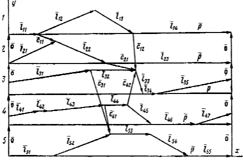
Cyclogram mechanisms machine-automaton can be represented as vector polygons [5], while maintaining the visibility of existing linear cyclogram and the possibility of using computers to optimize cyclogram mechanisms of machines, taking into account the accuracy of their production and work, as well as the mechanisms of interaction with each other. To obtain a mathematical model of the interaction mechanisms of machine-automaton with each other instead of segments, we introduce cyclogram of the vector (fig. 1) which are connected to each other, with the vector directed sequentially from one position to another - is denoted by the letter of the vector
ij
G
A
,n
- number of mechanisms,i
- number of mechanisms,j
- number of positioni
-mechanism,m
j
- number of positioni
-mechanism.Fig. 1. Vector model cyclogram.
Dynamics of Machine-automaton Jointly
with Cyclegram
Moreover, the projection of the vectors
G
A
ij on the X axis describesα
ij- phase angle triggering mechanisms, and the projection on the Y-axis indicates the value of movementδ
ijj
- position ofi
-mechanism, introduced as a dimensionless quantitymax max
max
,
,
1,..., ;
1,..., ,
ij
ij ij i
S
S
S
i
n j
m
S
δ
=
=
=
=
where
S
ij- movement ofj
- position ofi
-mechanism (dimensional quantity).Introduce vector
P
G
connecting point of beginning and end of the cycle. Projection vectorP
G
on the X axis is equal2
π
, on the Y axis is zero. In research cyclogram machine-automaton must take into account technological and structural constraints, ie precision manufacturing and work mechanisms, as well as connections of work mechanisms among themselves. Interaction mechanisms with each other reflected in the form of vectors of connectionc
G
ik, where1,...,
ik
=
r
,r
i- number of vectors connection ofi
- mechanism emerging fromj
- position. Direction vectors connectionrefers to the sequence of triggering mechanisms. The projection vectors connection to the X axis describes the time lag trigger mechanism, and the projection on the Y axis - the difference between the maximum displacement mechanisms.Impose cyclogram mechanisms at each other with zero vectors
O
G
(Fig. 1) connecting the boundary points of cyclogram mechanisms for Y axis.Up a system of vector equations, describing the mechanisms of machine-automaton in accordance (fig. 1).
1
1 1
,
1,..., ,
mi ij j
m n i ik ij ij
i j
P i
n
c
b
=
= =
⎫
=
=
∑
⎪⎪
⎬
⎪
=
∑ ∑
⋅
⎪⎭
G
G
A
G
G
A
(1)
where
b
ij∈
{
0, 1
±
}
Vector equations (1) describe the joint operation of mechanisms of machine-automaton. Project vector equations (1) on the axis X and Y.
1 1
1 1 1 1
2 , 0,
, ,
mi miij ij
j j
m m
n i n i
x y
ik ij ij ik ij ij
i j i j
c
b
c
b
δ
α
π
α
δ
= =
= = = =
⎫
=
=
⎪
∑
∑
⎪
⎬
⎪
=
∑ ∑
=
∑ ∑
⎪⎭
(2)
at
α
ij - phase angle triggering mechanisms, and movementδ
ij imposes constraints,
,
ij ij ij ij ij
α α
≥
δ
≥
δ
≥
δ
(3) whereα
ijm - the minimum allowable phase angles triggering mechanisms, determined from the condition of efficiency mechanisms,δ δ
ijв,
ijн- upper and lower limits of the designated designer.On the projection vectors of connection imposes constraints
,
xв x xн yв y yн ik ik ik ik ik ik
с
≥
с
≥
с
с
≥
с
≥
с
(4)
where xн х x
,
ун у уik ik ik ik ik ik
с
=
е
+ Δ
с
с
=
е
+ Δ
с
; x,
у ik ikе е
- the minimum allowable projection vectors of connection, defined by the technological conditions,Δ
с
ikx,
Δ
с
ikу- error projection vectors of connection,с с
ikxв,
ikув- upper limit imposed by the designer.Equations (2) and constraints (3,4) describe the joint work mechanisms (cyclogram) machine-automaton.
In steady motion machine-automaton with a centralized control system main shaft rotates at a constant speed
const
ω
=
, then a transition to the times of operation mechanismst
ij formulat
ij=
α ω
ij , and the period of the cycleT
=
2
π ω
.III. A MATHEMATICAL MODEL OF MOTION MACHINE-AUTOMATON BASED CYCLOGRAM
MECHANISMS
Machine-automaton contain a large number of mechanisms, co-coordinated work of which determines the efficiency of the machine. Cyclogram machine-automaton is quite complex and on its proper construction, as research has shown, depends significantly on its dynamics. In order to make it possible to influence the dynamics of machine-automaton through the restructuring of its cyclogram, it is necessary to identify the connection between the differential equations of motion of machine-automaton and the equations describing its cyclogram.
Consider this connection the example of machine-automaton consisting of motor of which are driven through the main shaft n-mechanisms, the dynamic model is presented as a series-parallel oscillatory system with n-mechanisms with nonlinear functions of mechanisms. These mechanisms are depicted as chain of the discrete elastic
с
i , resistanceβ
i, , inertialJ I
i,
i , motor torqueB
M
∂ , moments of resistanceM
i and kinematic elements,
1,...,
i
i
n
Π
=
(fig. 2).For the equations of motion mechanisms for machine-automaton for the dynamic model (fig. 2) we use the Lagrange equations II kind,
1
1 0,
m j i ij
i
j j j
m n
j i ij j
d T T V
Q h
d t
h h
λ
ϕ ϕ ϕ
ϕ
= +
=
⎫
⎛ ∂ ⎞ ∂ ∂
− + = + ∑ ⎪
⎜ ⎟
⎜∂ ⎟ ∂ ∂ ⎪
⎝ ⎠ ⎬
⎪
+ =
∑ ⎪⎭
where
ϕ ϕ
1, ,...,
2ϕ
n, n - generalized coordinates,λ
i - Lagrange multipliers,h h
ij,
i- some functions. T-kinetic energy of the holonomic system, V-potential energy of the system,Q
j -generalized forces .Fig. 2. Dynamic model of machine-automaton. To establish the connection between the equations describing the joint work mechanisms of machine-automaton (2-4) and the equations of dynamics (5) write the function of position and transfer functions of mechanisms of machine-automaton in the following form:
(
)
(
)
(
)
1 1
1
2 1 1
' '
1 1
1 '
2 1 1
'' ''
1 1
''
1
1
1
1
1
1
1
i i i i
j j
m
ij i ir i ir
j r r
i i i i
j j
m
ij i ir i ir
j r r
i i i i
j
ij i ir
r
L
L
L
L
L
L
L
L
ϕ α
ϕ
α
ϕ
α
ϕ α
ϕ
α
ϕ
α
ϕ α
ϕ
α
−
= = =
−
= = =
= Π ⎡⎣ ⎤⎦
⎡ ⎛ ⎞⎤ ⎛ ⎞ + Π ⎢ ⎜ ⎟⎥ ⎜ ⎟
⎝ ⎠ ⎝ ⎠
⎣ ⎦
Π ⎡⎣ ⎤⎦
⎡ ⎛ ⎞⎤ ⎛ ⎞ + Π ⎢ ⎜ ⎟⎥ ⎜ ⎟
⎝ ⎠ ⎝ ⎠
⎣ ⎦
Π ⎡⎣ ⎤⎦
+ Π
= Π ⋅ −
−
+
−
−
⋅
−
∑
∑
∑
= Π
−
−
+
−
−
⋅
−
∑
∑
∑
= Π
−
−
+
−
−∑
12 1
j m
i ir
j r
L
ϕ
−α
= =
⎫ ⎪ ⎪ ⎪ ⎪ ⎪ ⎪ ⎬ ⎪ ⎪ ⎪ ⎪ ⎪ ⎡ ⎛ ⎞⎤ ⎛ ⎞
⎪
⎜ ⎟ ⎜ ⎟
⎢ ⎝ ⎠⎥ ⎝ ⎠
⎣ ⎦
⋅
−
⎭∑
∑
(6)
where
i
=
1,...,
n
,L x
( )
- a step function of the form( )
0
1
,
0,
,
0.
x
L x
x
⎧
⎨
⎩
<
=
≥
' ''
,
,
ij ij ij
Π Π Π
- function of position, first transfer function, second transfer function on parts of phase angles triggeringij
α
of mechanisms .Expression (6) establish a connection between equations (5) describe the dynamics of machine-automaton and equations (2-4) cyclogram of machine-automaton. This method allows to solve various optimization tasks, where as the variable parameters used phase angles
α
ij andδ
ij value of movement cyclogram of machine, which gives the opportunity to improve their dynamics only by changing cyclogram mechanisms.IV. CONCLUSIONS
1. A vector model of cyclogram based on the presentation cyclogram machine-automaton in the form of vector polygons while maintaining the visibility of existing linear cyclogram and the possibility of using computers to optimize cyclogram mechanisms of machines, taking into account the accuracy of their production and work, as well as the mechanisms of interaction with each other.
2. A mathematical model of machine-automaton with elastic links and taking into account the of cyclogram its mechanisms. The equations for connection between the equations describing the joint work mechanisms machine-automaton and the equations of dynamics in the functions of positions and transfers functions of mechanisms.
V. EXAMPLE
One of the most loaded assembly of looms STB is slay mechanism [7]. It carries pushing weft threads and direct the formation of fabric, and also serves as a guide when moving microshuttles with thread.
Slay mechanism of loom STB is shown in fig. 3, where beam slay 1 has a longitudinal groove 2, which with the help of screw bolts 3 attached comb 4. To the front of beam slay screws 5 are attached clamps 6 teeth 7. Bolts 8 beam 1 is mounted on short blades 9 arranged on beam shaft 10. Beam shaft 10 is manufactured as a single unit with double-arm lever 11, placed at the top of the hermetically sealed box 12, which is filled with oil. Box 12 is attached to the base 13.
At the ends of double-arm lever 11 reinforced rollers 14, in contact with paired cams 15, sitting on the main shaft 16. The latter is located in the bottom of the box 12 and is integral with paired cams 15.
Fig. 3. Slay mechanism of loom STB.
The main shaft is composed of several sections connected by couplings 17. At the ends of sections, coming out of the box 12, ball bearings are placed next to that box are pressed into the hollow ring of glands.
of a pair of cams 15. Consider the dynamic model of slay mechanism of loom STB-180PN shown in fig. 4 is the basis of its main shaft of the machine, which are set in motion all of its mechanisms. The rotation of motor with the moment inertia
J
0=
const
transferred to the main shaft through a V-belt transmission with gear ratioП
0 and stiffnessc
1 And then to a pulley and crossbar friction clutch with a fixed rigidly to her brake drum having a moment of inertiaconst
J
1=
.Fig.4. Dynamic model of slay mechanism of loom STB-180PN.
The main shaft is divided into three sections, with the torsional stiffness
c c c
2, ,
3 4 and coefficients of resistance2
, ,
3 4β β β ,
J
2=
const
- moment of inertia of the camshaft of the first slay boxes.
J
3=
const
- moment of inertia of the cam shaft of the second slay boxes.J
4 - moment of inertia others mechanisms of loom,J c
5, ,
5 β5 - moment of inertia, stiffness and resistance coefficient of beam shaft,ϕ
0,
ϕ
1,
ϕ
2,
ϕ
3,
ϕ
4 - independent generalized coordinates, determining the absolute angular displacement of rotating masses,ϕ
5= Π
( )
ϕ
2,
ϕ
6= Π
( )
ϕ
3 - functions of position slay mechanism,М
D - torque of the driving forces of the electric motor,M
ПP- torque of slay mechanism,M
C - moment of resistance forces. This dynamic model is described by the following equations(
)
(
)
(
)
(
)
(
)
(
)
( )
(
)
0 0 1 0 0 1 1 0 0 1
1 1 1 1 0 0 2 1 2 1 1
0 0 2 1 2
2 2 2 2 1 3 2 3 2 2 1
5 5 5 5 6
3 2 3 3
5 5 6
3 3 3 3 2 4 3
(
) ( ) 0,
( )
( ) ,
( )
D
ПP
J c c
J c c
M J c
J c c
ϕ
ϕ
ϕ
ϕ ϕ
β ϕ
ϕ
β ϕ ϕ
ϕ
ϕ ϕ
ϕ ϕ
β ϕ ϕ
ϕ
ϕ ϕ
β ϕ ϕ
ϕ
β ϕ ϕ
ϕ
ϕ ϕ
ϕ ϕ
+ − Π + − + − −Π + − =
+ − + − + − + − − − − −
⎡ ⎤
′
+ − =⎢ ⎥Π
− −
⎣ ⎦
+ − + −
(
)
(
)
( )
(
)
4 3 3 2
5 6 5 6 5
4 3 4 3
5 6 5 5
4 4 4 4 5 4 4 3
(7)
( )
( )
( )
( ) ,
ПP
C
M J c
J c M
β ϕ ϕ
ϕ
ϕ ϕ
β ϕ ϕ
ϕ
β ϕ ϕ β
ϕ
ϕ ϕ
β ϕ ϕ
⎪ ⎪ ⎪ ⎪ ⎪ ⎪ ⎪⎪ ⎬ ⎪ ⎪ + − + ⎪ ⎪ − − − − −
⎡ ⎤
′ ⎪
+ − =⎢ ⎥Π
− − ⎪
⎣ ⎦
⎪
+ − + − = − ⎪⎭
where
( )
( )
( )
( )
( )
( )
2
5 2 2 5 2 2 2 2
2
6 3 3 6 3 3 3 3
, ,
,
ϕ
ϕ ϕ ϕ
ϕ ϕ
ϕ ϕ
ϕ
ϕ ϕ ϕ
ϕ ϕ
ϕ ϕ
′
′′
′
= Π
= Π
+ Π
′
′′
′
= Π
= Π
+ Π
Fig.5 by the solid lines shows the linear cyclogram of the five most important mechanisms loom STB-180PN, where the numbers denote the following mechanisms: 1-slay mechanism, 2- mechanism of return weft microshuttles , 3-fighting mechanism, 4- mechanism of compensator weft , 5- mechanism of lift weft microshuttles.
Fig. 6. Vector cyclorama of the five most important mechanisms loom STB-180PN.
Imagine cyclogram five most important mechanisms loom STB-180PN in vector form [1] (Fig. 6). We write the projection of vector equations in the x-axis, describing the joint work mechanisms of the machine
11 12 13 14
21 22 23
31 32 33 34 35
41 42 43 44 45 46 47 48
51 52 53 54 55
11 21 11
12 31 32 11 12 13
21 31 32 21 22
31 51 52 31
41 51 52 4
2 ,
2
2
2
2
;
;
x x x x xc
c
c
c
c
α
α
α
α
π
α
α
α
π
α
α
α
α
α
π
α
α
α
α
α
α
α
α
π
α
α
α
α
α
π
α
α
α
α
α
α
α
α
α
α
α
α
α
α
α
α
α
+
+
+
=
+
+
=
+
+
+
+
=
+
+
+
+
+
+
+
=
+
+
+
+
=
=
−
=
+
−
−
−
=
+
−
−
=
+
−
=
+
−
1 42 4342 31 32 41 42 43 44
;
xc
α
α
α
α
α
α
α
α
⎫
⎪
⎪
⎪
⎪
⎪
⎪
⎪
⎪
⎬
⎪
⎪
⎪
⎪
⎪
⎪
−
−
⎪
⎪
=
+
−
−
−
−
⎭
(8)At phase angles of mechanisms and the projection vectors connection imposes restrictions,
min
11 12 21
31 41 42
,
1 ,
0 30 ,
9 ,
0 30 ,
4 ,
5
x x x
ij ij
x x x
c
c
c
c
c
c
α
α
° ° °° ° °
⎫
′
≥
≥
≥
≥
⎪
⎬
′
≥
≥
≥
⎪⎭
(9)Where values
α
ijmin are given in table I. Table I. Valuesα
ijmin[degree]j i
1 2 3 4 5 6 7
1 0 60 60 0
2 60 70 0 3 70 0 2 10 60 4 60 3 30 60 50 0 30
5 0 70 0 60 0
Represent the functions of position
Π
( ) ( )
ϕ
2,
Π
ϕ
3 and transfer functionsΠ
′
( ) ( )
ϕ
2,
Π
′
ϕ
3 of slay mechanism in the form(
)
(
)
(
)
11 11 1 41, 1 1
2 1 1
11 11
1 4
1, 1 1
2 1 1
11 11
4 2
( )
1
1
( )
1
1
( )
1
i i
j j
j i r i r
j r r
i i
j j
j i r i r
j r r
i i j
L
L
L
L
L
L
L
ϕ
ϕ α
ϕ
α
ϕ
α
ϕ
ϕ α
ϕ
α
ϕ
α
ϕ
ϕ α
−
= = =
−
= = =
=
Π
= Π ⋅ −
⎡
⎣
−
⎤
⎦
+
⎡
⎛
⎞
⎤
⎛
⎞
+
Π
⎢
−
⎜
−
⎟
⎥
⋅
⎜
−
⎟
⎝
⎠
⎝
⎠
⎣
⎦
′
′
Π
= Π ⋅ −
⎡
⎣
−
⎤
⎦
+
⎡
⎛
⎞
⎤
⎛
⎞
′
+
Π
⎢
−
⎜
−
⎟
⎥
⋅
⎜
−
⎟
⎝
⎠
⎝
⎠
⎣
⎦
′′
′′
Π
= Π ⋅ −
⎡
⎣
−
⎤
⎦
+
′
+
∑
∑
∑
∑
∑
∑
∑
1, 1 1 11 1
1
j jj i r i r
r r
L
ϕ
α
L
ϕ
−α
= =
⎫
⎪
⎪
⎪
⎪
⎪
⎪⎪
⎬
⎪
⎪
⎪
⎪
⎪
⎡
⎛
⎞
⎤
⎛
⎞⎪
′
Π
⎢
−
⎜
−
⎟
⎥
⋅
⎜
−
⎟⎪
⎝
⎠
⎝
⎠
⎣
∑
⎦
∑
⎭
(10)
where
i
=
2,3
,L
( )
x
- step function of the form( )
⎩
⎨
⎧
≥
<
=
.
0
,
1
,
0
,
0
x
x
x
L
Equation (10) establishes connection between the dynamics of slay mechanism (equation (7)) and cyclogram of mechanisms of the machine (equation (8-9)
As optimization criterion cyclogram take dynamic coefficient slay mechanism
0 0
5 5 6 6
max(
/
/
)
d
K
=
ϕ ϕ
+
ϕ ϕ
,where
ϕ ϕ
50,
60 - acceleration slay mechanism without consideration of elasticshafts. Solves the following optimization task:min
→
d
K
(11) As variable parameters are taken phase angles slay mechanismα α α α
11,
12,
13,
14.As a result of solving task (11) obtain the optimal cyclogram of loom STB-180 with a pneumatic nozzle. Linear optimal cyclogram is shown in fig. 5, dotted lines. As a result of optimization cyclogram loom STB-180PN, coefficient of dynamic slay mechanism decreased by 5%.
REFERENCES
[1] L.V. Petrokas, “Reviews of cyclogram manufacturing machines and automatic production lines// Theory of automatic machines and pneumatic.” Moscow: Mashinostroenie, 1970, pp. 22-36.
345-350.
[3] G.V. Zeitlin, “Cyclogram of complex technology of automatic machines.” Engineering Science. Moscow, № 3, 1975, pp. 49-53.
[4] V.A Novgorodtsev, “Cyclogram machines are represented in the form of associated directed graph.” Harkov, 1982, iss. 33, pp. 57-60.
[5] А.А.Jomartov, А.А. Ermolov, “Optimization cyclogram machine-automaton циклограммы механизмов машины-автомата.” Engineering Science, Мosow, №6, 1987, pp. 42-45.
[6] I.I. Wolfson, “Dynamics calculations of cycle mechanisms.” Leningrad: Mashinostroenie, 1976, 328 p.