Journal of the American Chemical Society
Generating system-level responses from a
network of simple synthetic replicators
Jan W. Sadownik, Tamara Kosikova and Douglas Philp*
School of Chemistry and EaStCHEM, University of St Andrews, North Haugh, St Andrews, Fife KY16 9ST, United Kingdom
*Corresponding author e-mail: [email protected]
ORCID IDs:
Abstract
The creation of reaction networks capable of exhibiting responses that are properties of entire systems represents a significant challenge for the chemical sciences. The system-level behavior of a reaction network is linked intrinsically to its topology and the functional connections between its nodes. A simple network of chemical reactions constructed from four reagents, in which each reagent reacts with exactly two others, can exhibit upregulation of two products even when only a single chemical reaction is addressed catalytically. We implement a system with this topology using two maleimides and two nitrones of different sizes—either short or long and each bearing complementary recognition sites—that react pairwise through 1,3-dipolar cycloaddition reactions to create a network of four length-segregated replicating templates. Comprehensive 1H NMR
Introduction
Complex systems1 are constructed from intricate networks of interconnected components,
with their global functional and structural properties being determined by the nature of the recognition and reaction processes embedded within them. However, these systems often operate within environments that do not allow the individual interactions that give rise to the system-level behavior to be decoupled readily. Systems chemistry2 attempts to
create complexity and emergent phenomena through the application of wholly synthetic chemical platforms. In this approach, a collection of synthetic chemical entities, designed to interact and react in programmed ways, can express complex dynamic phenomena. This approach targets the creation of synthetic chemical systems whose properties are not simply the linear sum of the attributes of the individual components. Central to this goal is the design and synthesis of chemical structures that are capable of copying themselves or complementary partners, i.e., molecular replicators. By examining the dynamic processes that govern replication in synthetic chemical systems, it is possible to maintain structural and interactional simplicity in network components and design systems with well-defined chemistries and interactions. In this manner, a better understanding of the principles governing the creation and function of systems that express emergent phenomena can be developed, ultimately shedding light on the origins of biological complexity.
Currently, the general design principles2b,2c,3 required to create a self-replicating
system and engineer its behavior are well understood. In its simplest form, a self-replicating system is constructed from two molecules, where the product of their reaction acts a specific catalyst (template) for its own formation. Such templates allow the creation of systems that are responsive to feedback, i.e., the addition of pre-formed template acts as chemical input directing the synthesis of exact copies of that template. To date, self-replication has been demonstrated experimentally in systems fabricated from a variety of building blocks, ranging from more prebioticaly relevant oligonucleotide4 and peptide5,6
frameworks to completely synthetic, small organic7 molecules. With the advances in
networks, these systems are often very densely connected and susceptible to the reaction environment, e.g., pH. We have therefore become interested in exploiting systems constructed from synthetic replicators based on small organic molecules. Such systems9
can, in principle, offer tight control over network topology through careful manipulation of chemical structure and, hence, catalytic relationships, thus allowing the fabrication of networks with system-level behavior that moves beyond simple information transfer.
The emergent system-level2,3 behavior displayed by a network is linked intrinsically
to the topology of the network and, in particular, to the functional connections between the network nodes. An example of this type of phenomenon can be displayed (Figure 1) even by a simple chemical reaction network.
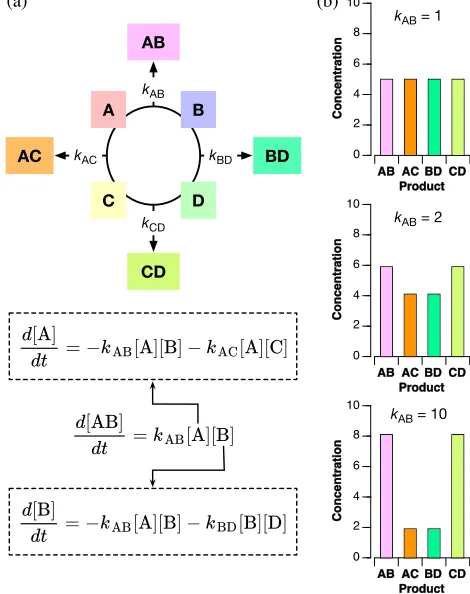
Figure 1 (a) A simple network of interconnected reactions can be created by four reagents A to D. Four
chemical transformations convert these starting materials into four products, AB, AC, BD, and CD.
Although the rate of formation of an individual product, e.g., AB, is described by a simple second order rate
law, the concentration terms in this differential equation are dependent intrinsically on two other reactions in the network. (b) If the values of all four rate constants are the same (kAB = kAC = kBD = kCD = 1), the final concentrations of all four products are identical. Increasing the value of one rate constant results in an increase in the final concentrations of two of the products. Thus, increasing kAB from 1 to 2 to 10, while kAC = kBD = kCD = 1, results ultimately in [AB] = [CD] = 8.1 and [AC] = [BD] = 1.9.
AB AC BD CD
0 2 4 6 8 10 C o n c e n tr a ti o n Product B A D C AB BD AC CD (a) kAC kAB kBD kCD
d[A] =− [A][B]− [A][C]
dt kAB kAC
d[AB] = [A][B]
dt kAB
d[B] =− [A][B]− [B][D]
dt kAB kBD
kAB = 1
AB AC BD CD 0 2 4 6 8 10 C o n c e n tr a ti o n Product
kAB = 2
AB AC BD CD
0 2 4 6 8 10 C o n c e n tr a ti o n Product
kAB = 10
[image:4.612.187.422.288.585.2]Within a network (Figure 1) constructed from four reagents that each react with exactly two others in the network, the rate of formation of an individual product, for example, AB, can be described (Figure 1a) by a second order rate law. However, each of the concentration terms within this rate law depends explicitly (Figure 1a) on two reactions in the network. For example, the change in concentration of A with respect to time depends on two reactions: A + B®AB and A + C®AC. Consequently, the transient concentrations of the reagents in any given reaction are connected either directly or indirectly to the transient concentrations of all of the other reagents in the network. Therefore, changes in the rate of consumption of one reagent must propagate throughout the entire network. If the values of all four rate constants (Figure 1b) are the same (kAB = kAC
= kBD = kCD), these interconnections will not express themselves and the final concentrations
of all four products are identical. By contrast, increasing the value of one rate constant, e.g., kAB, results in an increase (Figure 1b) in the final concentrations of two of the products, in
this case AB and CD.
In order for this network to operate in the manner described, it must be possible to address each of the four reactions individually and specifically in a catalytic manner. In this context, self-replicators provide the ideal vehicle for the implementation of this network topology, since they can act as specific catalysts for their own formation. We therefore envisaged (Figure 2) a network of four replicating templates that could be constructed through the combination of two pairs of reagents that each bear complementary recognition and reactive sites. These pairs of reagents are distinguished by the length of the spacer—either short (S) or long (L)—connecting the recognition site with the reactive site. Thus, the shortest self-replicator SNSM can be constructed by combination of SN and SM and would be expected to replicate itself through an autocatalytic cycle (Figure 2, SNSM ® SNSM). Similarly, the longest self-replicator
LNLM can be constructed by combination of LN and LM and would also be expected to template its own formation through an autocatalytic cycle (Figure2, LNLM ®LNLM). As there is a large size difference between these two replicators, we envisaged that, although each would be capable of catalyzing its own formation, crosscatalysis between SNSM and
By contrast, combination of SN with LM and LN with SM will lead to two self-complementary templates of intermediate size. Thus, whilst we would expect SNLM and
[image:6.612.65.550.191.469.2]LNSM to function as autocatalytic templates (Figure 2, SNLM ® SNLM and LNSM ® LNSM), there is also the possibility that crosscatalytic relationships could exist between these templates(Figure 2, SNLM ®LNSM and LNSM ®SNLM).
Figure 2 Four building blocks, SN, LN, SM, and LM, which all bear a recognition site and a reactive site
connected by either a short (S) or a long (L) spacer, can react with each other in a pairwise fashion to afford
four templates, SNSM, SNLM, LNSM, and LNLM. As a result of their different sizes, SNSM and LNLM
can participate only in autocatalytic cycles (SNSM → SNSM and LNLM → LNLM) in which they catalyze
their own formation. By contrast, SNLM and LNSM are of similar sizes. Therefore, in addition to catalyzing
their own formation through autocatalytic cycles (SNLM → SNLM and LNSM → LNSM), they can
potentially catalyze the formation of each other through crosscatalytic cycles (SNLM → LNSM and LNSM
→SNLM).
Molecular design
LNSM→LNSM
Autocatalytic Cycle
LNSM →SNLM
Crosscatalytic Cycle LNLM LNLM LNLM LNLM SNSM →SNSM
Autocatalytic Cycle SNSM SNSM SNSM SNSM LNLM LN LM SNSM SN SM Building Blocks
SN SM LM LN
LNSM LNSM SNLM LNSM LNSM SNLM SNLM LNSM LNSM SNLM
SNLM →LNSM
Crosscatalytic Cycle LNSM SNLM LNSM SNLM SNLM SNLM LNSM LN SM LN SM SNLM SN LM
LNLM →LNLM
Autocatalytic Cycle
SNLM→SNLM
Autocatalytic Cycle
In order to create a functional version of the replicator network shown in Figure 2, it is necessary to identify the correct chemical building blocks that are capable of reacting together to form the four replicating templates, SNSM, SNLM, LNSM, and LNLM.
In previous work, the replicating platform derived from nitrone SN and maleimide SM
has been utilized7b,7e,9a,9e in a number of scenarios. Using this successful design as a basis
for this work, we envisaged that we could create the required library of templates by simply incorporating an extended linker into the nitrone and maleimide components to afford long nitrone LN and long maleimide LM. Thus, pairwise combination of nitrones
SN and LN with maleimides SM and LM affords two pairs of templates10—SNSM and
LNLM, which have matched linker lengths, and SNLM and LNSM, which have mismatched linker lengths.
LNLM
LNSM SNLM
SNSM
SN
LM SM
We envisaged that this design, incorporating the long diphenylacetylene linker in both LN and LM would limit the number of crosscatalytic opportunities within this network, described conceptually in Figure 2. Thus, only SNLM and LNSM can potentially participate in mutually crosscatalytic pathways as the combination of one short and one long linker renders these two templates approximately equivalent in size. By contrast,
SNSM and LNLM—bearing either two short (phenyl) or two long (diphenylacetylene) linkers—are dramatically different in size. Therefore, we expect that they are fundamentally incompatible with each other and also with the linker mismatched pair (SNLM and LNSM).
Behavior of individual templates
Before exploring the network created by the four length-segregated templates in its entirety, it is necessary to establish the replicating efficiency of each of the four templates in isolation. To this end, we performed a series of kinetic experiments where the formation of each template was examined in CDCl3 at 273 K from its constituent components at
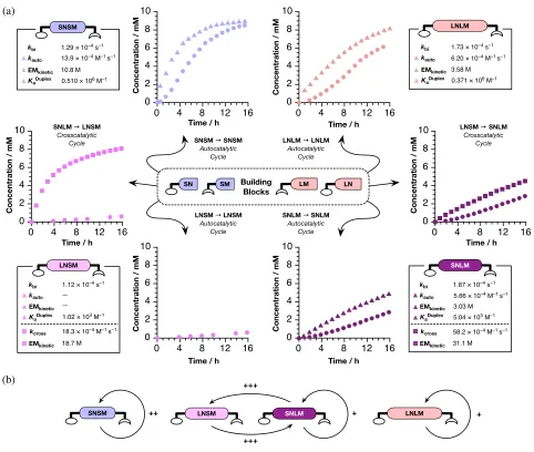
Figure 3 (a) Summary of kinetic data for individual templates determined by 500 MHz 1H NMR spectroscopy (273 K, CDCl3, 10 mM starting concentrations of reagents). In each case, the identity of the experiment is as follows: circles = uninstructed; triangles = autocatalytic template added; squares = crosscatalytic template added. (b) Schematic representation of the catalytic inter-relationships between the
templates SNSM, SNLM, LNSM, and LNLM. An arrow indicates a catalytic relationship, e.g., LNSM®
SNLM indicates that LNSM catalyzes the formation of SNLM. Efficiency: + = low (EMkinetic < 5 M); ++ = medium (5 M < EMkinetic < 15 M); +++ = high (EMkinetic > 15 M).
From the kinetic results shown in Figure 3a, it is clear that three of the templates,
SNSM, SNLM, and LNLM, show significant aptitudes for directing their own formation—i.e., the addition of the appropriate autocatalytic template at the start of each of the reactions results in significant enhancements of the rates of formation for each of these templates (triangles, Figure 3a). By contrast, LNSM in isolation did not display any
0 4 8 12 16
0 2 4 6 8 10
0 4 8 12 16
0 2 4 6 8 10
0 4 8 12 16
0 2 4 6 8 10
0 4 8 12 16
0 2 4 6 8 10
0 4 8 12 16
0 2 4 6 8 10
0 4 8 12 16
0 2 4 6 8 10 EMkinetic kbi kauto
KaDuplex
1.87 × 10⁻⁴ s–1
3.03 M 5.66 × 10⁻⁴ M–1 s–1
5.04 × 10³ M–1
EMkinetic kcross
31.1 M 58.2 × 10⁻⁴ M–1 s–1 EMkinetic
kbi kauto
KaDuplex
1.12 × 10⁻⁴ s–1
— —
1.02 × 10³ M–1
EMkinetic kcross
18.7 M 18.3 × 10⁻⁴ M–1 s–1
EMkinetic kbi kauto
KaDuplex
LNSM → LNSM Autocatalytic
Cycle SNSM → SNSM
Autocatalytic Cycle
Building Blocks
SN SM LM LN
LNLM → LNLM Autocatalytic
Cycle
SNLM → SNLM Autocatalytic
Cycle
Time / h
Concentration / mM
Time / h
Concentration / mM
Time / h
Concentration / mM
Time / h
Concentration / mM
Time / h
Concentration / mM
SNLM → LNSM Crosscatalytic
Cycle
LNSM → SNLM Crosscatalytic
Cycle 1.73 × 10⁻⁴ s–1
6.20 × 10⁻⁴ M–1 s–1
0.371 × 10⁶ M–1 EMkinetic
kbi kauto
KaDuplex
1.29 × 10⁻⁴ s–1
10.8 M 13.9 × 10⁻⁴ M–1 s–1
0.510 × 10⁶ M–1
LNLM SNSM LNSM SNLM + ++ +++ +++ + SNLM LNSM SNSM LNLM (a) 3.58 M (b)
Time / h
[image:9.612.68.550.67.475.2]obvious recognition-mediated reactivity and its rate of formation is close to that of the bimolecular background reaction (Supporting Figure S3). The solubility of this template limited the range of experiments that could be performed in order to establish the autocatalytic behavior of this template. Although we cannot discount completely the possibility that this template is capable of instructing its own formation, the efficiency of this process is undoubtedly extremely low.
Despite the lack of obvious autocatalytic activity exhibited by LNSM, a powerful crosscatalytic relationship exists between SNLM and LNSM. The addition of SNLM to the reaction between LN and SM results in a dramatic increase in the rate of formation of
LNSM (Figure 3a, squares, left). Similarly, the addition of LNSM to the reaction between
SN and LM results in a significant increase in the rate of formation of SNLM (Figure 3, squares, right)—close in magnitude to that observed for the template-directed autocatalytic formation of SNLM (Figure 3a, triangles, bottom right). Simulation and fitting (see Supporting Information for details) of the kinetic profiles shown in Figure 3a (and Supporting Figs. S1 to S4) allowed us to extract key kinetic parameters for these replicators (Figure 3a, data in boxes). A measure of the efficiency of each replicator comes from its value of EMkinetic, i.e., the effective molarity for the cycloaddition reaction achieved
by the replicating template within the relevant catalytically-important ternary complex. The catalytic relationships within this network are summarized in Figure 3b.
SNSM (EMkinetic = 10.8 M) and LNLM (EMkinetic = 3.6 M) replicate independently, with
SNSM being the more efficient of these two templates. As expected, the rate of formation of the linker-matched template SNSM is unaffected by the addition of LNLM. Similarly, the rate of formation of the linker-matched template LNLM is also unaffected by the addition of SNSM, confirming the absence of crosscatalysis between these two templates.
Only one of the linker-mismatched pair of templates, SNLM (EMkinetic = 3.0 M), is
capable of self-replication and the mutual crosscatalytic relationships that exist between
SNLM (EMkinetic = 18.7 M for the formation of LNSM) and LNSM (EMkinetic = 31.1 M for the
ωB97X/def2-SVP level of theory (see Supporting Information for details). The results of these calculations are summarized in Figure 4.
Figure 4 Stick representations of the calculated structures of the transition states accessed by (a)
[LN•SM•LNSM] and (b) [SN•LM•SNLM] leading to the corresponding template duplexes. Calculations
were performed at the ωB97X/def2-SVP level of theory using the PCM solvation model for chloroform. Hydrogen bonds are represented by dashed lines. Colored shaded areas indicated by letters are discussed in the main text. Carbon atoms are colored gray, nitrogen atoms blue, oxygen atoms red and hydrogen atoms white. Most hydrogen atoms are omitted for clarity. (c) Computed relationship (dashed line) between geometry and complex stability for the association of acetic acid and 2-acetoamido-6-methylpyridine. The colored data points represent the values observed for the angle ω in the associations between the
amidopyridines and carboxylic acids in [LN•SM•LNSM]‡ (•) and [SN•LM•SNLM]‡ (•). Calculations were
performed at the ωB97X/def2-TZVP level of theory using the PCM solvation model for chloroform.
The calculations reveal that plausible transition states are accessible from both the [LN•SM•LNSM] (Figure 4a) and [SN•LM•SNLM] (Figure 4b) ternary complexes, suggesting that both SNLM and LNSM should be capable of acting as templates for their own formation. Comparison of the transition state geometries accessed by the [LN•SM•LNSM] and [SN•LM•SNLM] ternary complexes with the geometry transition state calculated11 for the parent reaction between diphenyl nitrone and N-phenyl
maleimide reveals (see Supporting Information, Fig. S8) little evidence of significant distortions that might result in the reaction within the [LN•SM•LNSM] ternary complex being less efficient than the corresponding reaction within the [SN•LM•SNLM] complex.
(b)
(a) (c)
B
A
ω
R
e
la
ti
v
e
En
e
rg
y
/
k
J
0 1 2 3 4 5
Angle ω in degrees
0 10 20 30 40
LNSM
[image:11.612.84.528.123.356.2]However, there are three significant structural differences between the two transition states accessed from these ternary complexes. Firstly, both alkynes present in the transition state accessed from the [LN•SM•LNSM] ternary complex exhibit bending away from linearity (4° and 8°, highlight A in Figure 4a). By contrast, in the transition state accessed from the [SN•LM•SNLM] ternary complex, there is almost no bending (<2°) in either of the alkyne spacers. Whilst the bending potential for alkynes is somewhat soft, the presence of this bending could serve to disfavor reaction from [LN•SM•LNSM]. Secondly, the alkene protons present in the SM component of the transition state accessed from [LN•SM•LNSM] are located within a pocket that contains other hydrogen atoms that bear partial positive charges (highlight B in Figure 4a). These electrostatic interactions will serve to destabilize [LN•SM•LNSM]‡. Finally, and perhaps most significantly, there
are significant differences between the geometries observed for the recognition elements present in the transition states accessed from two ternary complexes. In the case of [LN•SM•LNSM]‡, both carboxylic acid units are twisted by more than 30° with respect to
the mean plane of the pyridine ring to which they are hydrogen bonded. By contrast, within [SN•LM•SNLM]‡, the twists are only 12° and 23°. In order to assess the likely
impact of these differences in geometry within the recognition elements of these two complexes, we performed a series of calculations at the ωB97X/def2-TZVP level of theory in which the angle ω (Figure 4c) subtended between mean plane of the COOH fragment of acetic acid and the mean plane of the pyridine ring to which the acid is hydrogen bonded is increased. These calculations reveal that, as expected, the lowest energy geometry is the coplanar arrangement of the two recognition elements (ω = 0°), as this arrangement allows the optimum geometry for both hydrogen bonds present in this complex. As ω increases, the complex becomes significantly less stable. Based solely on the different geometries of the recognition elements observed in the two transition state structures computed for [LN•SM•LNSM]‡ and [SN•LM•SNLM]‡, the geometries observed in recognition
elements of [LN•SM•LNSM]‡ are expected, at this level of theory, to be 4.64 kJ mol–1 less
stable than those observed in [SN•LM•SNLM]‡. If this difference is expressed fully in the
the EMkinetic for the formation of LNSM would be << 1 M. This expectation is consistent
with the observed data and it is therefore possible that the inability of LNSM to template its own formation efficiently arises from destabilization of the [LN•SM•LNSM] ternary complex as it enters the transition state for the formation of the self-complementary template.
Network behavior
Having established the catalytic relationships between and kinetic parameters for the individual templates, we were able to create a kinetic model capable of simulating the behavior of the complete network shown in Figure 2. These simulations revealed (Figure 5, center) that, in the absence of any template instruction, simply mixing the two nitrones and two maleimides at starting concentrations of 10 mM results in a population of replicators after 16 hours in which all four replicators have significant representations— the predicted ratio of SNSM : SNLM : LNSM : LNLM is 1.8 : 1.3 : 1.5 : 1.
In order to benchmark our simulation, we performed an experiment in which SN,
LN, SM and LM were dissolved at starting concentrations of 10 mM in CDCl3 at 273 K.
The formation of the four corresponding templates was monitored by 500 MHz 1H NMR
spectroscopy over 16 hours (see Figure S5 for an example spectrum) and these data were used to construct the concentration-time profiles for each replicator within this mixture. Pleasingly, there is excellent agreement (Figure 5, center) between the experimental data (the observed ratio of SNSM : SNLM : LNSM : LNLM is 1.7 : 1.5 : 1.4 : 1) and those calculated using our kinetic simulation.
Figure 5 A reagent pool containing two nitrones (SN and LN) and two maleimides (SM and LM) is instructed by the addition of one (Single Input) or two (Dual Input) replicating templates. In all cases, the system responds in specific and predictable ways to the template input and there is good agreement between the behavior of the system predicted from kinetic simulation and experiment. Experiments: 273 K,
CDCl3, 10 mM. For details of simulations, see Methods. Data points and bars are shaded according to their
association with a specific template—SNSM (white), LNSM (light gray), SNLM (dark gray), LNLM (black).
% En h a n c e m e n t −60 0 60 120 180 % En h a n c e m e n t −60 0 60 120 180 % En h a n c e m e n t −60 0 60 120 180 % En h a n c e m e n t −60 0 60 120 180 % En h a n c e m e n t −60 0 60 120 180 % En h a n c e m e n t −60 0 60 120 180 % En h a n c e m e n t −60 0 60 120 180 % En h a n c e m e n t −60 0 60 120 180 SN SM LN LM SNSM Simulation Experiment Single Input Dual Input No Input SNLM SNLM LNLM SNSM %EF %EF %EF %EF %EF %EF %EF %EF C o n c e n tr a ti o n / m M 0 2 4 6 8 10
Time / h
0 4 8 12 16
C o n c e n tr a ti o n / m M 0 2 4 6 8 10
Time / h
0 4 8 12 16
C o n c e n tr a ti o n / m M 0 2 4 6 8 10
Time / h
0 4 8 12 16
C o n c e n tr a ti o n / m M 0 2 4 6 8 10
Time / h
0 4 8 12 16
C o n c e n tr a ti o n / m M 0 2 4 6 8 10
Time / h 0 4 8 12 16
C o n c e n tr a ti o n / m M 0 2 4 6 8 10
[image:14.612.94.526.61.611.2]In the case of single template inputs, either SNSM or SNLM, (Figure 5, top half), it is evident from the simulations that the instruction of the network by the appropriate template results in the upregulation (%EF > 0, Figure 5) of not only the added template but also its linker-length related partner. Thus, when SNSM provides the instruction, LNLM
is also up-regulated, since it is created from the two long components that are not required for the formation of SNSM. In other words, the addition of a linker-length matched template (SNSM) results in the upregulation of both templates in this group (SNSM and
LNLM). Similarly, when SNLM provides the instruction, LNSM is up-regulated as it is created from the short and long components that are not required for the formation of
SNLM. In order to verify these predictions experimentally, we performed two experiments in which SN, LN, SM, and LM were dissolved at starting concentrations of 10 mM in CDCl3 at 273 K. In one experiment, SNSM was added at a concentration of 3.7 mM
and in the second experiment, SNLM was added at a concentration of 3.2 mM. In both cases, the formation of the four templates was monitored by 500 MHz 1H NMR
spectroscopy over 16 hours and these data were used to construct the concentration-time profiles for each replicator within this mixture. Subsequently, these profiles were used to compute the corresponding %EF for each replicator (Figure 5, top half). Pleasingly, there is a good agreement between the behavior of the network predicted by the simulations and that observed experimentally. In constructing the kinetic model, certain simplifications were made with respect to single point recognition events and the rate constants associated with bimolecular reactions (see Supporting Information for details) and, most likely, it is these decisions that are responsible for the slight differences between the experiments and simulations.
In the case of dual template inputs (Figure 5, bottom half), the situation is more complex. Simulations predict that the simultaneous addition of both linker-matched templates, SNSM and LNLM, will reinforce the instruction to the network to make only linker-matched templates. In order to verify this prediction experimentally, we performed an experiment in which SN, LN, SM, and LM were dissolved at starting concentrations of 10 mM in CDCl3 at 273 K and templates SNSM and LNLM were added at concentrations
monitored by 500 MHz 1H NMR spectroscopy over 16 hours. The data acquired were used
to construct the concentration-time profiles for each replicator and to compute the corresponding enhancements (Figure 5, bottom half). Once again, there is a good agreement between the behavior of the network predicted by the simulations and that observed experimentally. Finally, we examined the response of the network to two contradictory instructions, namely SNLM and LNLM. The addition of SNLM should instruct the network to form linker-mismatched templates, whereas the addition of LNLM
should instruct the network to form linker-matched templates. Simulations predict that the addition of these two templates should result in the upregulation of SNLM, LNSM, and LNLM and the down-regulation of SNSM. We verified this prediction experimentally in the same type of experiment as described previously, in which SNLM and LNLM were added at concentrations of 4.4 mM and 5.7 mM to a mixture of SN, LN, SM, and LM at starting concentrations of 10 mM in CDCl3 at 273 K. The data acquired were used to
construct the concentration-time profiles for each replicator and to compute the corresponding %EF (Figure 5, bottom half). As before, there is good agreement between the behavior of the network predicted by the simulations and that observed experimentally.
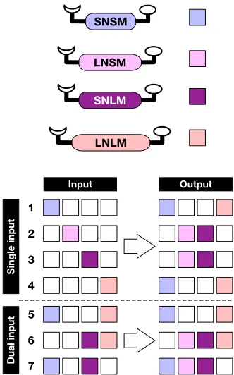
The system-level behavior expressed by this network of synthetic replicators in response to template inputs is summarized in Figure 6. When a mixture of the building blocks SN, LN, SM, and LM is instructed by a single template (Figure 6, entries 1 to 4), the network topology determines the output, i.e., all templates of the same linker type, matched or mismatched, are up-regulated. For example, addition of SNSM catalyzes the formation of this template, removing SN and SM rapidly from solution. Since, SNLM and
LNSM both require one of the short components, these two templates are down-regulated (%EF < 0, Figure 6). Since LNLM requires only the long components LN and LM, it benefits from the template-directed formation of SNSM and is up-regulated. This behavior is identical to that exhibited by the simple network shown in Figure 1.
and Figure 6, entry 5) the template effects are reinforcing. When two templates are added that belong to different linker classes (for example, the addition of SNLM and LNLM, Figure 6, entry 6) the template effects are, in principle, in competition. As a result of the crosscatalytic relationships between SNLM and LNSM, both of these templates are up-regulated. The addition of LNLM mitigates the effect of this crosscatalytic connection by providing a catalytic pathway for the formation of LNLM. Therefore, the only species in solution whose formation is not enhanced directly in a catalytic manner is SNSM. Consequently, this template is down-regulated. A similar outcome is observed when
SNSM and SNLM are added simultaneously at the start of the reaction (Figure 6, entry 7 and Figure S7). In this case LNLM is the only species in solution whose formation is not enhanced directly in a catalytic manner and, consequently, it is this template that is down-regulated.
Figure 6 The output of the replicator network shown in Figure 2 is determined by the nature of the
instructing template that is added. Entries 1 to 4 show single inputs where the network topology determines that the input of a single template of a particular linker type, matched or mismatched, results in the
up-regulation of both templates of the same linker type. Entries 5 to 7 illustrate more complex cases where more
than one instructing template is added.
LNSM
SNLM
LNLM SNSM
Input
Single input
Output
Dual input
1
2
3
4
5
6
[image:17.612.222.388.344.610.2]Conclusions
Networks of replicating templates that interact and react in well-defined ways can serve as models for the kind of primitive metabolic pathways that may have arisen12 on the early
Earth. In this work, we have demonstrated that it is possible to create such a network, whose behavior can be directed specifically by the introduction of instructional templates that possess a very limited structural and interactional lexicon. By maintaining tight control over the structural complexity of the network components, it is possible to quantify the relative contributions of each replicator to the overall operation of the network. Ultimately, the topology of this network is such that it is capable of expressing system-level behavior through the introduction of instructional replicating templates and the addition of a single input instruction elicits upregulation of more than one product in a programmed manner. The programmability of the network also extends to situations where multiple instructional templates are added simultaneously. This work creates a foundation for the construction and exploitation of replicator networks under conditions where dynamic covalent libraries9e,13 or diffusion phenomena7b are coupled with
Acknowledgements
The financial support for this work was provided by EaStCHEM and the Engineering and Physical Sciences Research Council (Grant EP/K503162/1).
Competing financial interests
The authors declare no competing financial interests.
Supporting Information
Notes and References
(1) (a) Mitchell, M. Complexity: A Guided Tour; Oxford University Press: New York, 2009. (b) Corbett, P. T.; Sanders, J. K. M.; Otto, S. Angew. Chem. Int. Ed. 2007, 46, 8858. (c) Boccaletti, S.; Latora, V.; Moreno, Y.; Chavez, M.; Hwang, D. U. Phys. Rep. 2006, 424, 175. (d) Severin, K. Chem. Eur. J. 2004, 10, 2565. (e) Newmann, M. E. J. SIAM Rev.
2003, 45, 167. (f) Barabási, A.-L. Linked: The New Science of Networks; Perseus Book Group: New York, 2002. (g) Strogatz, S. H. Nature 2001, 410, 268.
(2) (a) Miljanić, O. Š. Chem 2017, 2, 502. (b) Duim, H.; Otto, S. Beilstein J. Org. Chem. 2017, 13, 1189. (c) Ashkenasy, G.; Hermans, T. M.; Otto, S.; Taylor, A. F. Chem. Soc. Rev.
2017, 46, 2543. (d) De la Escosura, A.; Briones, C.; Ruiz-Mirazo, K. J. Theor. Biol. 2015, 381, 11. (e) Mattia, E.; Otto, S. Nat. Nanotechnol. 2015, 10, 111. (f) Ruiz-Mirazo, K.; Briones, C.; de la Escosura, A. Chem. Rev. 2014, 114, 285. (g) von Kiedrowski, G.; Otto, S.; Herdewijn, P. J. Syst. Chem. 2010, 1, 1. (h) Stankiewicz, J.; Eckardt, L. H. Angew. Chem. Int. Ed. 2006, 45, 342.
(3) (a) Kosikova, T.; Philp, D. Chem. Soc. Rev. 2017, DOI: 10.1039/c7cs00123a.
(b) Bissette, A. J.; Fletcher, S. P. Angew. Chem. Int. Ed. 2013, 52, 12800. (c) Huck, J.; Philp, D. In Supramolecular Chemistry: From Molecules to Nanomaterials; John Wiley & Sons, Ltd.: New York, 2012; pp 1415–1446. (d) Vidonne, A.; Philp, D. Eur. J. Org. Chem 2009, 2009, 593. (e) von Kiedrowski, G. Bioorganic Chem. Front. 1993, 3, 113. (4) (a) Plöger, T. A.; von Kiedrowski, G. Org. Biomol. Chem. 2014, 12, 6908. (b) Lincoln, T.
a; Joyce, G. F. Science 2009, 323, 1229. (c) Paul, N.; Joyce, G. F. Proc. Natl. Acad. Sci. USA 2002, 99, 12733. (d) Sievers, D.; Von Kiedrowski, G. Chem. Eur. J. 1998, 4, 629. (e) Luther, A.; Brandsch, R.; von Kiedrowski, G. Nature 1998, 396, 245. (f) von
Kiedrowski, G.; Wlotzka, B.; Helbing, J.; Matzen, M.; Jordan, S. Angew. Chem. Int. Ed. Engl. 1991, 30, 423. (g) von Kiedrowski, G. Angew. Chem. Int. Ed. Engl. 1986, 25, 932. (5) (a) Sadownik, J. W.; Mattia, E.; Nowak, P.; Otto, S. Nat. Chem. 2016, 8, 264. (b)
Colomb-Delsuc, M.; Mattia, E.; Sadownik, J. W.; Otto, S. Nat. Commun. 2015, 6, 7427. (c) Carnall, J. M. A.; Waudby, C. A.; Belenguer, A. M.; Stuart, M. C. A.; Peyralans, J. J.-P.; Otto, S. Science 2010, 327, 1502. (d) Rubinov, B.; Wagner, N.; Matmor, M.; Regev, O.; Ashkenasy, N.; Ashkenasy, G. ACS Nano 2012, 6, 7893. (e) Rubinov, B.; Wagner, N.; Rapaport, H.; Ashkenasy, G. Angew. Chem. Int. Ed. 2009, 48, 6683.
(6) (a) Samiappan, M.; Dadon, Z.; Ashkenasy, G. Chem. Commun. 2011, 47, 710. (b) Li, X.; Chmielewski, J. J. Am. Chem. Soc. 2003, 125, 11820. (c) Issac, R.; Chmielewski, J. J. Am. Chem. Soc. 2002, 124, 6808. (d) Yao, S.; Ghosh, I.; Zutshi, R.; Chmielewski, J. Angew. Chem. Int. Ed. Engl. 1998, 37, 478. (e) Yao, S.; Ghosh, I.; Zutshi, R.; Chmielewski, J. J. Am. Chem. Soc. 1997, 119, 10559. (f) Severin, K.; Lee, D. H.; Kennan, A. J.; Ghadiri, M. R. Nature 1997, 389, 706. (g) Lee, D. H.; Granja, J. R.; Martinez, J. A.; Severin, K.; Ghadri, M. R. Nature 1996, 382, 525.
6723. (c) Dieckmann, A.; Beniken, S.; Lorenz, C. D.; Doltsinis, N. L.; Von Kiedrowski, G. Chem. Eur. J. 2011, 17, 468. (d) Dieckmann, A.; Beniken, S.; Lorenz, C.; Doltsinis, N. L.; von Kiedrowski, G. J. Syst. Chem. 2010, 1, 10. (e) Kassianidis, E.; Philp, D. Angew. Chem. Int. Ed. 2006, 45, 6344. (f) Pearson, R. J.; Kassianidis, E.; Slawin, A. M. Z.; Philp, D. Chem. Eur. J. 2006, 12, 6829. (g) Kindermann, M.; Stahl, I.; Reimold, M.; Pankau, W. M.; von Kiedrowski, G. Angew. Chem. Int. Ed. 2005, 44, 6750. (h) Wang, B.; Sutherland, I. O. Chem. Commun. 1997, 1495. (i) Rotello, V.; Hong, J.-I.; Rebek, J. J. J. Am. Chem. Soc. 1991, 113, 9422. (j) Tjivikua, T.; Ballester, P.; Rebek, Jr., J. J. Am. Chem. Soc. 1990, 112, 1249.
(8) (a) Dadon, Z.; Samiappan, M.; Wagner, N.; Ashkenasy, G. Chem. Commun. 2012, 48, 1419. (b) Ashkenasy, G.; Dadon, Z.; Alesebi, S.; Wagner, N.; Ashkenasy, N. Isr. J. Chem. 2011, 51, 106. (c) Dadon, Z.; Wagner, N.; Ashkenasy, G. Angew. Chem. Int. Ed.
2008, 47, 6128. (d) Ashkenasy, G.; Jagasia, R.; Yadav, M.; Ghadiri, M. R. Proc. Natl. Acad. Sci. USA 2004, 101, 10872. (e) Saghatelian, A.; Yokobayashi, Y.; Soltani, K.; Ghadiri, M. R. Nature 2001, 409, 797. (f) Severin, K.; Lee, D. H.; Martinez, J. A.; Vieth, M.; Ghadiri, M. R. Angew. Chem. Int. Ed. Engl. 1998, 37, 126. (g) Yao, S.; Ghosh, I.; Zutshi, R.; Chmielewski, J. Nature 1998, 396, 447. (h) Lee, D. H.; Severin, K.; Yokobayashi, Y.; Ghadiri, M. R. Nature 1997, 390, 591.
(9) (a) Kosikova, T.; Hassan, N. I.; Cordes, D. B.; Slawin, A. M. Z.; Philp, D. J. Am. Chem. Soc. 2015, 137, 16074. (b) Allen, V. C.; Robertson, C. C.; Turega, S. M.; Philp, D. Org. Lett. 2010, 12, 1920. (c) Kassianidis, E.; Pearson, R. J.; Wood, E. A.; Philp, D. Faraday Discuss. 2010, 145, 235. (d) Xu, S.; Giuseppone, N. J. Am. Chem. Soc. 2008, 130, 1826. (e) Sadownik, J. W.; Philp, D. Angew. Chem. Int. Ed. 2008, 47, 9965. (f) Kassianidis, E.; Philp, D. Chem. Commun. 2006, 4072.
(10) The 1,3-dipolar cycloaddition reaction between a nitrone and maleimide can give rise to two diastereoisomers. In the trans diastereoisomer, the proton originally located on the nitrone is in a configuration on the isoxazolidine ring that is trans to the two protons originally present on the maleimide dipolarophile. In the cis
diastereoisomer, this relative stereochemical relationship is cis. In this network, only the trans diastereoisomer is capable of taking part in template-directed replication processes, and, thus, the notation of the cycloadduct products capable of replication will omit the trans descriptor throughout. In all recognition-mediated experiments reported here, after 16 h, the ratio of [trans]:[cis] ranged from a minimum of 8:1 to > 100:1.
(11) Kosikova, T.; Philp, D. J. Am. Chem. Soc. 2017, 139, 12579.
(12) (a) Muchowska, K. B.; Varma, S. J.; Chevallot-Beroux, E.; Lethuillier-Karl, L.; Li, G.; Moran, J. Nat. Ecol. Evol. 2017, 1, 1716. (b) Ariga, K. Mater. Chem. Front. 2017, 1, 208. (c) Shapiro, R. Q. Rev. Biol. 2006, 81, 105.
For Table of Contents Only:
Output
LNSM
SNLM
LNLM SNSM Input
SN
SM
LN
LM Building
Blocks
1 1
1 1
1 1
1 1

![Figure 4 Stick representations of the calculated structures of the transition states accessed by (a) [LN•SM•LNSM] and (b) [SN•LM•SNLM] leading to the corresponding template duplexes](https://thumb-us.123doks.com/thumbv2/123dok_us/8727507.385689/11.612.84.528.123.356/representations-calculated-structures-transition-accessed-corresponding-template-duplexes.webp)