A Thesis Submitted for the Degree of PhD at the University of Warwick
http://go.warwick.ac.uk/wrap/70945
This thesis is made available online and is protected by original copyright. Please scroll down to view the document itself.
谨以此论文献给我的父亲,母
亲,外公,外婆,二姨,二姨
Optical Wireless MIMO
Communication
by
Hao Du
Thesis
Submitted to the University of Warwick
for the degree of
Doctor of Philosophy
School of Engineering
I
Table of Contents
List of Figures ... V List of Tables ... XII Acknowledgements ... XIII Declaration ... XV Abstract ... XVI Publications ... XVIII
Chapter 1 Introduction ... 1
1.1 Overview ... 1
1.2 The Indoor Optical Wireless System ... 2
1.2.1 Visible Light ... 2
1.2.2 Infrared Light ... 3
1.2.3 Challenges of Indoor Optical Wireless ... 5
1.3 Wireless MIMO System ... 7
1.4 Optical Wireless MIMO System ... 11
1.4.1 Categories ... 11
1.4.2 The advantages and challenges ... 11
1.5 Organization of the Thesis ... 14
Reference Chapter 1 ... 17
Chapter 2 Literature Review ... 20
2.1 Infrared Communication Technology ... 20
2.1.1 Introduction ... 20
2.1.2 Characteristic ... 20
2.1.3 Principles ... 22
2.1.4 Standard ... 23
2.2 Mathematical Model ... 24
II
2.3.1 Introduction ... 24
2.3.2 Space-Time Combining ... 27
2.3.3 MIMO Cases ... 28
2.4 Optical Communication System Model ... 30
2.5 Optical Wireless MIMO System ... 34
2.6 Optical MIMO Network... 39
2.7 Summary ... 41
References Chapter 2 ... 41
Chapter 3 Optical MIMO System Based on APD Receiver ... 45
3.1 Introduction ... 45
3.2 Optical MIMO ... 46
3.3 Noise in APDs ... 47
3.3.1 Introduction of APD Noise ... 47
3.3.2 Large Deviations Theory Approach ... 49
3.4 SISO System ... 49
3.4.1 Results using the Parameters in [18] ... 50
3.4.2 Gaussian Approximation without Fading ... 51
3.4.2 Gaussian Approximation with Fading ... 56
3.5 OW Diversity ... 57
3.6 Transmitter Diversity MISO (Multiple input single output) System ... 58
3.6.1 Monte Carlo Integration ... 60
3.6.2 Importance Sampling ... 61
3.7 Receiver Diversity SIMO (single input multiple output) System ... 64
3.8 Transmitter and Receiver Diversity (MIMO System) ... 67
3.9 Summary ... 70
References for Chapter 3 ... 71
Chapter 4 Optical Wireless MIMO System Based on OOK Modulation ... 75
III
4.2 System Model ... 75
4.3 Transmitter and Receiver design ... 77
4.4 System Controller ... 91
4.5 Research Method ... 92
4.5.1 Geometry Model ... 92
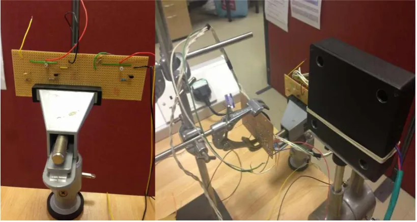
4.5.2 Introduction of research instruments ... 97
4.5.3 Experiment progress ... 100
4.6 Summary ... 107
References Chapter 4 ... 108
Chapter 5 Optical Wireless MIMO System Based on PPM Modulation ... 109
5.1 Introduction ... 109
5.2 Modulation Defined by IrDA ... 111
5.3 System Module ... 113
5.4 Transmitter and Receiver Design ... 117
5.4.1 IrDA Higher speed (1.1-1.3, FIR-4PPM) ... 117
5.4.2 IrDA 1.0 (SIR-Pulse Modulation) ... 118
5.5 Summary ... 120
References Chapter 5 ... 120
Chapter 6 Performance Analysis... 121
6.1 Introduction ... 121
6.2 Experiment Performance Analysis ... 122
6.2.1 OOK Modulation 100kHz ... 122
6.2.2 OOK Modulation 1MHz ... 127
6.2.3 OOK Modulation in the Dark at 100kHz ... 130
6.2.4 OOK Modulation in the Dark at 1MHz ... 133
6.2.5 SIR-RZI Modulation ... 138
6.2.6 PPM Modulation 1MHz ... 143
IV
Chapter 7 BER Curve-Fitting ... 148
7.1 Introduction ... 148
7.2 OOK Modulation ... 150
7.2.1 OOK 100kHz 70 – 140cm Distance ... 150
7.2.2 OOK 1MHz 70 – 110cm Distance ... 153
7.2.3 OOK 1MHz 120 – 140cm Distance ... 156
7.2.4 OOK 100kHz Darkroom 0-9cm Displacement ... 158
7.2.5 OOK 1MHz Darkroom 0 – 6cm Displacement ... 160
7.2.6 OOK 1MHz Darkroom 7 – 10cm Displacement ... 164
7.3 PPM and SZI Modulation ... 166
7.3.1 PPM 1MHz 0 – 25cm Displacement ... 166
7.3.2 PPM 1MHz 30 – 60cm Displacement ... 169
7.3.3 SIR-RZI 100kHz 2X4 50 – 130cm Distance ... 171
7.3.4 SIR-RZI 100kHz 4X4 20 -60cm Distance ... 174
7.3.5 SIR-RZI 100kHz 4X4 70 – 150cm Distance ... 176
7.4 Summary ... 179
Chapter 8 Conclusion ... 180
8.1 Summary ... 180
8.2 Recommendations for future research. ... 183
Appendix I: Circuit Component Value of OOK based MIMO System ... 186
Appendix II: Circuit Design for PPM/RZI based MIMO System ... 188
1. IrDA Higher speed (1.1-1.3, FIR-4PPM)... 188
2. IrDA 1.0 (SIR-Pulse Modulation) ... 190
V
List of Figures
Figure 1-1 Visible Light Communication System………2
Figure 1-2 Optical Channel Simulation Model………3
Figure 1-3 LOS and Diffuse Channel………...4
Figure 1-4 Optical MIMO System……….13
Figure 1-5 LOS MIMO system………..14
Figure 2-1 2X2 Alamouti STBC………25
Figure 2-2 Infrared Channel Model………32
Figure 2-3 Spatial Multiplexing………...………...…...37
Figure 2-4 Spatial diversity………37
Figure 2-5 Beam formation………..……..38
Figure 2-6 Optical MIMO Network………...39
Figure 2-7 Optical MIMO Network Transmitting Matrix………...…...40
Figure 3-1 OW SISO System……….49
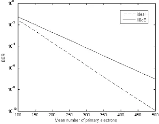
Figure 3-2 BER of SISO APD system for ideal conditions and an extinction ratio of 10 dB………..51
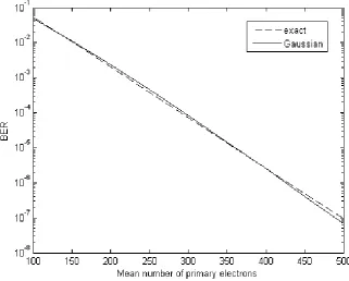
Figure 3-3 BER using large deviations and the Gaussian approximation for a 10 dB extinction ratio………54
VI
Figure 3-5 The BER results with and without fading……….57
Figure 3-6 OW MISO System………58
Figure 3-7 BER for SISO and 2-1 MISO………...59
Figure 3-8 Comparison of Analytical, MC and IS BER results for MISO Systems..63
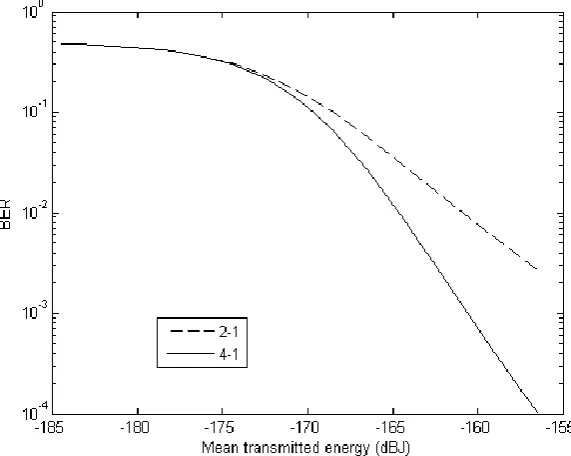
Figure 3-9 BER results for 4-1 and 2-1 MISO obtained using IS………..63
Figure 3-10 OW SIMO System………..64
Figure 3-11 BER results for 4-1 and 2-1 SIMO obtained using IS………66
Figure 3-12 BER results for 1-4 SIMO and 4-1 MISO………..67
Figure 3-13 OW MIMO System……….68
Figure 3-14 BER results for 1-2 SIMO and 2-2 MIMO……….68
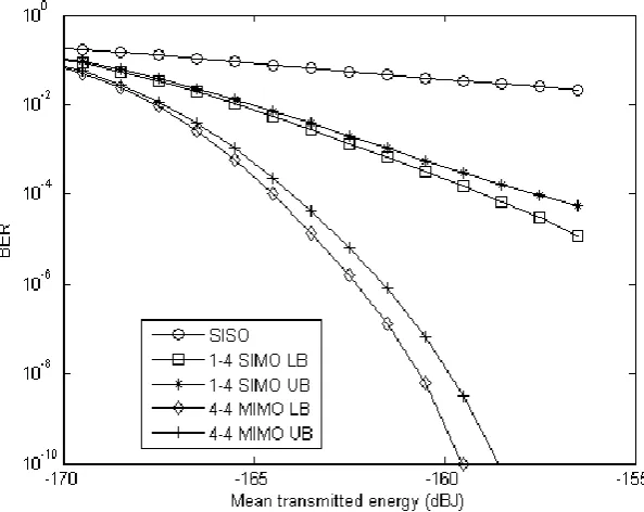
Figure 3-15 BER results for 1-4 SIMO and 4-4 MIMO……….69
Figure 4-1 Indoor infrared 2X2 MIMO system schematic……….76
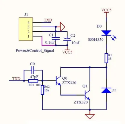
Figure 4-2 (a) Transmitter 100kHz (b) Transmitter 1MHz………..………..78
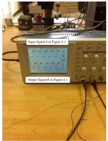
Figure 4-3 Transmitted and Received Tested Signals of 1MHz MIMO System…...80
Figure 4-4 1MHz Transmitter Design………....81
Figure 4-5 Receiver and First Amplifier……….……...83
Figure 4-6 Second Amplifier…………..………84
VII
Figure 4-8 (a) Performance before and after comparator (b) 100kHz receiver with
amplifier and comparator model………....86
Figure 4-9 1-10MHz Transmitter Circuit………...87
Figure 4-10 1-10MHz Receiver Circuit……….88
Figure 4-11 Receiver 100kHz (Left) & 1-10MHz (Right)……….89
Figure 4-12 (a) Four 1-10MHz transmitters; (b) Four 1-10MHz receivers…….…...90
Figure 4-13 (a) PCI 7200; (b) The PCI-installed Computer connected the transmitters and receivers………...91
Figure 4-14 Infrared MIMO System Geometric Model……….92
Figure 4-15 Infrared MIMO System Geometric Model Considering Displacement.94 Figure 4-16 (a) OOK Transmitters Stand; (b) OOK Receivers Stand………95
Figure 4-17 SIR/PPM Modulation Transceiver Geometric Diagram……….96
Figure 4-18 Receivers of Infrared OOK MIMO system………97
Figure 4-19 (Up) OOK MIMO Transmitters; (Bottom) 4PPM MIMO Tranceivers..98
Figure 4-20 Experiment for Infrared 4X4 OOK System……….…...99
Figure 4-21 Experimental Progress ……….101
Figure 4-22 Experiment 1……….102
Figure 4-23 Experiment 2……….103
VIII
Figure 4-25 Experiment 4……….106
Figure 4-26 SISO Experiment……….……….107
Figure 5-1 The Symbol Structure of OOK and PPM Modulation………110
Figure 5-2 FIR-4PPM Module – Single circuit and 2X2 Module………113
Figure 5-3 4ppm and SIR Transmitters and Receivers (4X4 Transceivers)………114
Figure 5-4 4PPM and SIR 4X4 Infrared MIMO System (same boxes)…………...115
Figure 5-5 SIR System Flow………115
Figure 5-6 4PPM Infrared System………117
Figure 5-7 SIR Infrared System………...118
Figure 5-8 Clock…..……….119
Figure 6-1 Distance = 20cm……….123
Figure 6-2 Distance = 50cm……….124
Figure 6-3 Distance = 70cm……….125
Figure 6-4 Distance = 100cm………...125
Figure 6-5 Distance = 140cm………...126
Figure 6-6 Distance = 20cm……….……....128
Figure 6-7 Distance = 60cm……….128
Figure 6-8 Distance = 140cm………..………...129
IX
Figure 6-10 Displacement = 3cm……….131
Figure 6-11 Displacement = 7cm……….132
Figure 6-12 Displacement = 10cm………...132
Figure 6-13 Displacement = 0cm……….134
Figure 6-14 Displacement = 2cm……….134
Figure 6-15 Displacement = 4cm……….135
Figure 6-16 Displacement = 6cm……….135
Figure 6-17 Displacement = 8cm……….136
Figure 6-18 Displacement = 10cm………...136
Figure 6-19 Distance = 20cm………...139
Figure 6-20 Distance = 80cm………...139
Figure 6-21 Distance = 150cm……….140
Figure 6-22 Distance = 20cm………...141
Figure 6-23 Distance = 80cm………...141
Figure 6-24 Distance = 150cm……….142
Figure 6-25 Displacement = 5cm 2X4……….144
Figure 6-26 Displacement = 25cm 2X4………...144
Figure 6-27 Displacement = 40cm 2X4………...145
X
Figure 7-1 Fitting Distance 70cm – 140cm………..150
Figure 7-2 Estimated value of a1, b1 and c1………152
Figure 7-3 Fitting Distance 70cm – 110cm………..154
Figure 7-4 Estimated value of a0,a1 and b1………155
Figure 7-5 Fitting Distance 120cm – 140cm………156
Figure 7-6 Estimated value of p1 and p2………..157
Figure 7-7 Fitting 0 – 9cm Displacement……….158
Figure 7-8 Estimated value of a0, a1, b1 and w………...160
Figure 7-9 Fitting Displacement 0cm – 6cm………161
Figure 7-10 Estimated value of a0, a1, b1 and w……….163
Figure 7-11 Fitting Displacement 7cm – 10cm………164
Figure 7-12 Estimated value of a and b………165
Figure 7-13 Fitting 0 – 25cm Displacement……….167
Figure 7-14 Estimated value of p1 and p2………168
Figure 7-15 Fitting 30 – 60cm Displacement………...169
Figure 7-16 Estimated value of a and b………170
Figure 7-17 Fitting 50 – 130cm Distance……….172
Figure 7-18 Estimated value of a1, b1 and c1………..173
XI
Figure 7-20 Estimated value of a1, b1 and c1………..175
Figure 7-21 Fitting 70 – 140cm Distance……….176
XII
List of Tables
Table 2-1 Algorithms used in the normal optical channel models…...32
XIII
Acknowledgements
First and foremost I offer my sincerest gratitude to my supervisor, Professor Roger
Green, who has supported me though out my thesis with his patience and knowledge
whilst allowing me the room to work in my own way. I attribute the level of my
Ph.D degree to his encouragement and effort and without him this thesis, too, would
not have been completed or written. One simply could not wish for a better or
friendlier supervisor.
Secondly, Dr Yunfei Chen, as my second supervisor, has provided me with many of
the research ideas, methods and insight throughout my work in this thesis as well as
many others. Dr Chen has done much more than a second supervisor. Without whose
encouragement and effort I could not finish the experiment and research definitely. I
feel so lucky to have such a great supervisor during my Ph.D research.
In my daily work I have been blessed with a friendly and cheerful helper Professor
Xiaojun Ji, a visitor form Shanghai Jiaotong University, PRC. In many ways I have
learnt much from him, like circuit design, soldering, LEDs and Microcontroller
selection.
The School of Engineering has provided the support and equipment I have needed to
XIV
It is certainly that I am grateful to my parents, Weiping Du and Jingping Zhan, and
all the members of my big big family, who bestowed ability and strength in me to
study in University of Warwick, and complete this work. They always give me the
strength and wisdom throughout my whole life. Their encouragement and concern
are invaluable.
To Aunty Zhang, I deeply thank you for your advice and patience on improving my
English academic writing these years.
Finally, thank you Miss Yenan Wu, thank you for everything you did for me during
these years, support me by encouraging me and giving all the help you could (the
happiness, the tolerance, and delicious food!) And thank everyone who loves me,
my friends, no matter the ones in China, Imperial College, Nottingham University
XV
Declaration
This thesis is submitted in partial fulfilment for the degree of Doctor of
Philosophy under the regulations set out by the Graduate School at the University of
Warwick. This thesis is solely composed of research completed by Hao Du, except
where stated, under the supervision of Professor Roger Green and Dr Yunfei Chen
between the dates of January 2010 and September 2013. No part of this work has
been previously submitted to any institution for admission to a higher degree.
Hao Du
XVI
Abstract
This thesis provides an in-depth investigation and evaluation of infrared optical
wireless MIMO communication systems to be applied in both indoor and outdoor
environment. The principle objective of the research is to demonstrate both the
advantages and disadvantages of the optical wireless MIMO systems using different
modulation types.
The first part provided analyses of important OW configurations using APD
receivers using WMC model and SISO, MISO, SIMO and MIMO configuration.
Thus, an analytical expression for 2-1 MISO, 1-2 SIMO and MIMO was
successfully developed. This part also illustrates the coding gains possible using
diversity schemes for APD OW systems. In the presence of strong fading, the SISO
approach is rendered virtually useless, whereas diversity offers acceptable BER
values. The results underpin the approach of this thesis, where indoor PIN diode
based experimental measurements confirm the gains offered by diversity.
In the second part of the work, several optical wireless MIMO systems applicable for
the indoor environment are developed for three different modulation types, OOK
modulation, PPM modulation and SIR-RZI modulation. These modulations are used
in optical MIMO systems are studied for which, mathematical models that evaluate
the BER performance of the MIMO system for different axis displacement and for
different distances between transmitters and receivers. Based on the results, the PPM
system has been shown to present the best BER performance, including high
XVII
evaluated, which demonstrates a high level of correlation with the results derived
from empirical models at 93%. Thus, the mathematical models developed and used
for the specified evaluation appear to correspond reasonably well, and can be applied
XVIII
Publications
H. Du, R. J. Green, Y. Chen, “Optical wireless 2X2 indoor MIMO system based on
OOK modulation”, Proc. 15th IEEE Conference on Transparent Optical Networks
(ICTON), pp. 1-3, 2013 [3 pages].
H. Du, R. J. Green, Y. Chen, “Optical Wireless Indoor MIMO System based on
OOK and PPM Modulations”, submitted to IET Communications.
H. Du, R. J. Green, Y. Chen, “Infrared Indoor MIMO Communication System using
1
Chapter 1 Introduction
1.1 Overview
Optical wireless (OW) technology presents a potential application in
contemporary communication systems. It also promises to supplement wireless
radio-frequency (RF) technologies, which have been broadly used for commercial
communication applications, such as WLAN and Bluetooth. Most important of all,
the bandwidth of the OW is available worldwide, and the unlicensed OW technology
does not interfere with radio frequency bands.
During the last two decades, OW technology has played the vital role for promoting
high speed indoor communications as a complementary and extended scheme to the
RF indoor wireless systems. The main advantages of OW communications include
cost-effective, broad bandwidth access, high quality data-transmission, no
interference with RF-based communication signals, and highly-secured
2 1.2 The Indoor Optical Wireless System
Indoor optical wireless communications are mainly associated with visible light
and infra-red technology applications.
1.2.1 Visible Light
Figure 1-1 Visible Light Communication System [2]
A typical visible light communication system (VLC) using white LEDs is illustrated in Figure 1-1. In this figure, both lighting and communication link are provided by the white LED. As is mentioned in [2], the blue light used as the signal carrier can be
extracted by employing the blue waveband optical filter at the receiver side to enhance the bandwidth of the system. The most important component in Figure 1-1 is the LED.In addition to pure colour LEDs, two other white LEDs are also used:
1. Red-green-blue LEDs;
3
In [2], the second option is generally the preferred one for lighting because of the
lower complexity in comparison with the one in three colours. One thing to be
noticed is that the bandwidth of the device is between 1-10MHz, mainly due to the
slow temporal response of the visible LEDs. [3, 4]
1.2.2 Infrared Light
The infrared light wireless communication system offers much higher data
transmission rate than that of the visible light system because of its more powerful
laser source and its wider modulation bandwidth laser source are used. Figure 1-2
shows the optical channel simulation model. In this figure, by using the collated
detector, the modulated signals are received after transmitting in the free space (the
simulated signal noise are added into the free space channel), and then the signals
would be demodulated and output. The data are modulated by specific modulation
technology, and transmitted by the transmitters; secondly, the noises are added into
the channel; thirdly, the modulated signals are detected by the detectors; and finally,
detected signals would be demodulated and exported.
Modulation
Signal
Free space
channel
Noise
+
Detector
Demodulation
and output
4
References [2] and [5] demonstrate that in free space it is possible to achieve a data
rate at the Gbps level through IR links when communicating over a distance of
several km. However, it is highly recommended that the higher power transmitting
within a very narrow field-of-view (FOV) is applied.
For indoor Infrared communications, there are two basic types of transmission
configuration:-
1. Line of sight (LOS) transmission;
2. Non-Line of sight transmission.
Figure 1-3 illustrates the classification of infrared wireless links according to the
degree of directionality of transmitters and receivers (Line of sight, Non-Line of
sight and Mixed). [6]
5
Because of the multipath induced inter-symbol interference (ISI), although more
reflective in comparison with LOS links, non-LOS links offer lower bandwidth but a
wider Field of Views (FOV) and a certain level of mobility (in the wireless channel,
the signal multipath propagation will generate ISI. This is because with the
increasing of data rate, the interval between the symbols will reduce to a certain
extent which can’t be distinguished by the detector, and thus results in ISI. A
non-LOS OW system is discussed in [7] where parallel low speed transmission has been
proposed. Reference [8] describes a high speed parallel optical wireless
communication system. Haykin introduced an artificial neural network in [9] which
could mitigate the multipath induced ISI in indoor OW links. However, different
from non-LOS links, LOS links are capable of achieving higher power and
bandwidth efficiency in high speed applications and at the same time, low signal loss
and pulse dispersion from multipath. However, LOS links are limited in the area
coverage related applications. In [10, 11] beam broadening is considered as an
alternative technology for improving the mobility and coverage of LOS links. In
summary, the infrared light systems can have better performances than the visible
light systems, at the cost of more complicated designs and more compromises.
1.2.3 Challenges of Indoor Optical Wireless
The first challenge comes from the limitation of bandwidth and transmission
speed. In [2], it was reported that by using a blue filter to remove the other
wavelength, it is easy to achieve a high bandwidth from a visible light source. When
the bandwidth is fixed, the multiple input and multiple output (MIMO) systems can
6
reach several Gbps) by transmitting data in parallel to achieve multiplexing gain. As
the limiting parameter, the channel matrix can be improved by using an imaging lens
system [12].
Second challenge comes from the dimming of light, mainly for the visible light
system, which affects the link performance. In [3], two approaches were described to
solve the specific problems of:
1. Reducing the amplitude;
2. Using pulse width modulation (PWM).
Both can help to increase the performance of the light system and can deliver desired
output performance. However, the second approach will reduce the average
throughput.
The third challenge comes from infrared communications. The transmission power is
small due to eye safety related considerations. Consequently, infrared wireless
communications are considered to be challenging due to the low power budget. In
addition, it remains difficult to design and produce OW receiver with high-speed,
high sensitivity and high efficiency. In [2], the typical diameter of photo-detectors is
less than 100μm for transmitting data at 10Gbps, which may make it extremely
7 1.3 Wireless MIMO System
MIMO is broadly applied in the fourth generation mobile communication
standards, such as IEEE 802.16e Worldwide Interoperability for Microwave Access
(WiMAX,), Long Term Evolution (LTE), IEEE 802.11n, and the next-generation
wireless LAN (WLAN) standard. MIMO also refers to spatial diversity as it uses
multi antennas to perform multi-channel transmission and reception of data.
The ground-breaking work of wireless mobile communication systems by using
MIMO technology was initially accomplished by the AT & T Bell laboratory in the
1990s. In 1995, in [12], Teladar demonstrated the MIMO capacity in the path-loss
channel. In 1996, Foshini developed MIMO processing algorithms and revealed in
Angle - Bell Labs Layered Space-Time (D-BLAST). [12] In 1998, Tarokh discussed
MIMO space-time codes, while during the same year, Wolniansky used vertical -
Bell Labs layered Space-Time (V-BLAST) algorithm to develop a MIMO indoor
system, and tested the 20bps/MHz spectral efficiency. [13] These accomplishments
attracted the worldwide attention from academia and industries. According to the
number of transceivers at both ends of the antenna, other systems can be considered
as a special case of MIMO, such as a Single-Input Single-Output (SISO) system, a
MIMO system, a Single-Input Multiple-Output (SIMO) system, and a Multiple-Input
Single-Output (MISO) system. In conclusion, MIMO systems use multiple
8
The development of MIMO technology maximizes the space capacity to improve the
data transmitting performance, and also increases the wireless space coverage of the
system. When a transmitted signal is reflected, it will produce more than one copy,
and each of which is a spatial stream. The SISO system can only send or receive one
spatial stream, whereas the MIMO system uses multiple antennas to send and receive
multiple spatial streams, and therefore is able to distinguish different signals sent
from different “transceivers”. As the application of multi-antenna system allows
more data to be sent, the use of multiple antennas at the transmitter or receiver can
significantly reduce the channel fading effect and minimize the error rate. It is
generally recognized that the diversity gain can be as high as Nt * Nr (the minimum
number of transmitter and receiver). Another interesting MIMO technology is related
to space time coding. The primary application of space time coding is to use space
and time domain encodings to achieve a certain degree of spatial and time diversity
and hence reduces the bit error rate of the system.
Typically, multipath effects cause fading and hence cause undesirable impacts.
However, the experiment results show that in MIMO systems, multipath can
somehow be considered as a positive and desirable factor. After a space-time coding,
a data stream S(k) is divided into N information sub-streams C (k)i , where i = 1, ...,
N,. The N sub-streams are transmitted out by N antennas and received by M
receiving antennas. The multi-antenna receivers use space time coding technology to
process, separate and decode data sub-streams. In particular, N sub-streams are
simultaneously sent to the channel occupying the same bandwidth to avoid the
9
receiving antenna is independent, the MIMO system can create multiple parallel
spatial channels for the data transmitting through such parallel spatial channels
independently, consequently, it increases data rate. Moreover, the system capacity is
one of the most important parameters to characterize the communication systems,
which represents the maximum transmission data rate of the communication system.
As for a N transmit antennas and a M receive antennas in a MIMO system, and
assuming that the channel is Rayleigh fading channel, and the N and M are large
enough, the channel capacity C can be described approximately as below:
2
min( , ) log ( / 2)
C M N B
(1.1)
where B is the signal bandwidth, ρ is the average SNR of the receiving signal, min
(M, N) represents the smaller number between M and N. It is shown that when power
and bandwidth are fixed, the capacity of a MIMO system increases linearly with the
minimum number of antennas. As a result, MIMO has great potential for improving
the capacity of a wireless communication system.
As an example, MIMO has been used in the IEEE 802.11n standard to achieve high
data rate and high reliability. This standard is used to bridge users with the wireless
access of user terminals in office LAN and campus networks, but the data rate can
only reach 2Mbps at present. Because the data rate and transmission distance can’t
meet the growing demand on bandwidth, higher security of data transmission and
more convenient roaming services, the IEEE group has initiated several new
10
The bandwidth of 802.11n is 2.4GHz and 5GHz, and the WLAN transmission data
rate varies from 54Mbps (802.11a and 802.11g) to 108Mbps, up to 500Mbps by
applying MIMO and Orthogonal Frequency Division Multiplexing (OFDM)
technology. Moreover, the quality of wireless transmission is greatly enhanced.
The bandwidth of 802.11n will allow a WLAN transmission rate to be increased
more than 10 times in comparison with the current transfer data rate, which can
easily support high-quality music, picture voice and video transmission. Such
improvement offers an opportunity for people in the office with Wi-Fi access to
transmit data and communicate with other people.
The 802.11n standard also uses smart antenna technology, in which the multiple
independent antenna arrays can dynamically adjust the beam to ensure that WLAN
users receive stable signals and minimize interference from other signals.
Consequently, the area coverage can be extended to over 1 2
km . This makes the
application of mobile receiving instruments develop towards a broader context in the
11 1.4 Optical Wireless MIMO System
1.4.1 Categories
Due to different application ranges and channels, the optical wireless MIMO
system can be divided into two categories: indoor and outdoor wireless MIMO
systems. The main applications for indoor optical wireless MIMO are the indoor
computer network and communication between office equipment. The indoor
wireless MIMO system channel is affected by indoor room light, as well as
multipath problem caused by the wall reflection, which results in the inter-symbol
interference (ISI).
Outdoor wireless MIMO systems are mainly applied for free space communications
such as airplane and satellite communication, which are affected by the natural
background light (sun, moon, etc.), atmospheric scintillation and turbulence, also the
attenuation caused by the weather (fog, rain, clouds and other natural phenomena).
1.4.2 The advantages and challenges
As having been discussed by many research groups, optical wireless technology
may offer unlimited bandwidth, which has the potential to meet the high market
demand on indoor wireless access applications, such as voice over IP, images, mp3
or other music data transmissions, streaming video, etc. An optical wireless system
12
corresponding photodiodes. Over the past few decades, optical wireless MIMO
technology has been developed rapidly, and succeeded with substantial advantages
such as offering higher data rates within the same bandwidth, license free, low or no
interference as those experienced in a RF-based system (the commercial technology),
and many others with potential application development. [14]
However, the main disadvantage of high data rate in the optical wireless
communication is related to the limitation of transmission distances (normally less
than 10m). When the transmission distances exceeds 10m, a direct light source with
a narrow Angle-of-View (AOV) is highly recommended. In [13], it is explained that
the optical wireless signal channels are significantly affected by large path loss and
background noise such as sunlight, room light and other ambient light sources,
meanwhile, the requirements for a certain signal to noise ratio (SNR) requires a
limitation in bandwidth, resulting in a consequent limitation in data rate.
Comparing the two types of optical wireless transmissions, namely, the visible light
link and the infrared link, the infrared wireless system has demonstrated great
potential as described in [12] due to its high speed transmission and low rate of
interference. Moreover, it is considered to be both cost effective and
simply-designed, and the infrared wireless system provides an easier access for realization
of various applications than those of fibre optic systems and radio wireless systems.
The infrared wireless MIMO system is considered to be highly competitive in
13
Since 2010, the demand for high capacity data transmission increases substantially,
especially on wireless communication, including optical wireless communications.
As described in Section 1.3, MIMO systems have attracted great attention in the
applications of radio wireless communications. As has been described in many
publications, in comparison with SISO wireless system, an optical wireless MIMO
system employs multiple antennas at both source and receiver end and thus, it may
achieve high speed data transmission without increasing power and bandwidth. [12,
13] A typical optical MIMO system is shown in Figure 1-4: [13]
Data Modulate Modulate Modulate LED LED LED Photodiode Photodiode Photodiode + + + Demodul ate and Detector Channel Noise
Figure 1-4 Optical MIMO System adapted from Takase et al. in [13]
As shown in [15], O’Brien et al. built a 4X4 white LED MIMO indoor optical
system, in which the transmitters and receivers were arranged on two 0.2m pitches
14
Figure 1-5 LOS MIMO system (a) Schematic (b) Receiver
(c) Transmitter (d) Schematic of imaging MIMO system adapted [15]
The can be considered as the typical non-imaging indoor wireless system model. In
this system, four white LED sources are used as separate transmitters, each of which
is on a 0.2m pitch. The data streams are transmitted on these 4 channels, and the
resulting signal recorded. Also [15] shows the received data are correctly.
1.5 Organization of the Thesis
Most of the existed research did not incorporate any experimental results from
optical wireless systems, and all their discussion and conclusion were based on the
analytical models and simulation results. The novelty of this project includes the
design and building of several experimental optical wireless MIMO systems and the
evaluation of the relationships between BER and distance/displacement using
15
experimental systems and fitted mathematical relationships have not been obtained
before.
More specifically, this project furthers studies on OW MIMO by providing three
infrared MIMO experimental systems using different modulations to describe the
detailed process and the experiment methodology in developing the infrared MIMO
systems. On-off keying (OOK), serial infrared protocol – return to zero inverted
(SIR-RZI) and pulse positon modulation (PPM) are considered. The BERs of three
systems are measured and compared, and the advantage and disadvantage of these
systems are illustrated and discussed. To the best of the authors’ knowledge, neither
the built system nor their experimental results have been published in the literature
before. Moreover, using curve fitting, the experimental results of BER are fitted as
functions of system parameters to derive some mathematical models that have not
been studied before. The results obtained from the specified experiments indicate
that the developed system is viable for indoor optical applications as verified by root
mean squared error.
The contributions of this project are three-fold. Firstly, it builds three new optical
wireless MIMO systems with different modulations in metal boxes. Secondly, it
conducts useful experiments on the effects of several important parameters on the
system performance. Thirdly, based on these experimental results, it performs
curve-fitting to provide some mathematical relationships between these parameters and the
16
The work in this thesis is presented in the following chapters, and each chapter has
own objects and connection with all the others.
Chapter 2 represents the principle and background knowledge of the technology used
in this thesis.
Chapter 3 provides analyses of important OW configurations using APD receivers.
First, the WMC model was employed to analyse the SISO configuration using a
large deviations approach. Then, comparison with a Gaussian approximation showed
that the latter was reasonable for the parameters considered, and made for a more
tractable approach. Thus, an analytical expression for 2-1 MISO was successfully
developed.
Chapter 4 and 5 discuss three different hardware optical wireless MIMO systems. In
the Chapter 4, the theory and design concept of the 4X4 infrared MIMO system
using OOK modulation are discussed that has a working bandwidth is between
100kHz to 10MHz. Also all the designed circuits, the controller boards and
experimental flow will be introduced in Chapter 4.
Chapter 5 provides a 4PPM based 4X4 infrared MIMO system, whose bandwidth is
17
frequency (10kHz-1MHz) for 4X4 system are built as the reference model. The
design circuits and controller flow will be explained.
In Chapters 6 and 7, all the experiments using different modulation and MIMO
technologies (multiplexing and diversity) are illustrated, and the fitted mathematical
models are obtained using the experiment results. Chapter 8 concludes all of the
work, and is showing the further research which may be investigated.
Reference Chapter 1
[1] J. Grubor, S. Randel, K. D. Langer, J. W. Walewski, “Broadband Information
Broadcasting Using LED-Based Interior Lighting”, IEEE Journal of Lightwave
Technology, vol. 26, no. 24, 2008.
[2] H. Le Minh, Z. Ghassemlooy, D. O’Brien, G. Faulkner, “Indoor Gigabit
Optical Wireless Communications - Challenges and Possibilities”, Proc. 12th
IEEE Conference on Transparent Optical Networks (ICTON), 2010 [6 pages].
[3] H. Le Minh, D. O’Brien, G. Faulkner, L. Zeng, K. Lee, D. Jung, and Y. Oh,
“High-speed visible light communications using multiple-resonant
equalization”, IEEE Photonics Technology Letters, vol. 20, no. 14, pp.
1243-1245, 2008.
[4] J. Grubor, K. D. Langer, S. C. J. Lee, T. Koonen, and J. W. Walewski,
“Wireless high-speed data transmission with phosphorescent white-light
LEDs”, Proc. 23rd European Conference and Exhibition of Optical
Communication (ECOC), 2007 [2 page post deadline paper].
18
optical link over 4.4 km”, Electronics Letters, vol.35, pp. 578-579, 1999.
[6] J. R. Barry, Wireless Infrared Communications, Kluwer, 1994.
[7] F. E. Alsaadi, J. M. H. Elmirghani, “Performance evaluation of 2.5Gbit/s and
5Gbit/s Optical wirelesssystems employing a two dimensional adaptive beam
clustering method and imaging diversity detection”, IEEE Journal on Selected
Areas in Communications, vol. 27, no. 8, pp. 1507-1519, 2009.
[8] G. Ntogari, T. Kamalakis, T. Sphicopoulos, “Performance analysis of space
time block codingtechniques for indoor optical wireless systems”, IEEE
Journal on Selected Areas in Communications, vol. 27, no. 9, pp. 1545-1552,
2009.
[9] S. Haykin, “Neural networks expand SP's horizons”, IEEE Signal Processing
Magazine, vol. 13, no. 2, pp. 24-49, 1996.
[10] A. Hussain, J. J. Soraghan, T. S. Durrani, “A new adaptive functional-link
neural-network-based DFEfor overcoming co-channel interference”, IEEE
Transactions on Communications, vol. 45, no. 11, pp. 1358-1362, 1997.
[11] S. Rajbhandari, Z. Ghassemlooy, M. Angelova, “Bit error performance of
diffuse indoor optical wireless channel pulse position modulation system
employing artificial neural networks for channel equalisation”, IET
Optoelectronics, vol. 3, no. 4, pp. 169-179, 2009.
[12] D. Takase, T. Ohtsuki, “Optical Wireless MIMO Communications”, Proc.
IEEE Grobal Telecommunications Conference (GLOBECOM), vol. 2, pp.
928-932, 2004 [5 pages].
[13] D. Takase, T. Ohtsuki, “Optical Wireless MIMO (OMIMO) with Backward
Spatial Filter (BSF) in Diffuse Channels”, Proc. IEEE International
19
[14] R. Mesleh, R. Mehmood, H. Elgala, H. Haas, “Indoor MIMO Optical Wireless
Communication Using Spatial Modulation”, Proc. IEEE International
Conference on Communications (ICC), pp. 1-5, 2010 [5 pages].
[15] D. O’Brien, “Multi-Input Multi-Output (MIMO) Indoor Optical Wireless
Communications”, Proc. 2009 Conference Record of the Forty-Third Asilomar
Conference on Signals, Systems and Computers, pp. 1636-1639. 2009 [4
20
Chapter 2 Literature Review
2.1 Infrared Communication Technology
2.1.1 Introduction
The infrared wavelength range varies from 0.70μm to 1mm, whereas the region of
300μm ~ 1mm is often referred as sub-millimeter. In today’s infrared
communication technology, the major factors affecting the quality of atmospheric
infrared transmission are absorption and scattering. [1]
2.1.2 Characteristic
Infrared communication technology is considered suitable for applications in
low-cost, cross-platform, point-to-point high-speed data connection of embedded systems,
device interconnection, and information gateway systems. As is described in [1],
infrared communication technology is recognized worldwide for its applications in
wireless data transmissions and communications, which is supported by a great
number of hardware and software platforms with primary application features shown
as below: [1]
1. Use mutual conversion between electrical pulse and infrared light pulse for
21
2. Broadly used to replace point-to-point cable connection.
3. The newly developed infrared communication standard is compatible with the
existing communication standards.
4. Small angle (cone angle of 30 degrees or less), short-range, point-to-point
straight line data transmission and high security.
5. High transfer rate. Fast infrared protocol (FIR) at 4Mbps has been broadly used,
and Very Fast infrared protocol (VFIR) at 16Mbps has been released. A new
“Gigabit-IR” standard is also undergoing trials and validation. [2]
6. An infrared signal is reflected from non-light-transmissive material, such as
walls, etc. Therefore, the same infrared equipment can be used in different
physical spaces.
7. Occupying lower channel resources than that of RF technology with higher
security features. Eavesdropping on data within a confined space is not easy
with infrared technology applications.
8. Infrared communication has excellent inter-changeability and versatility because
of the optical transmission capability and limited transmitting space.
9. No harmful radiation. It has been scientifically proven that infrared is a spectrum
causing no harm to human in special areas, within well-known eye safety limits.
[3]
In addition, an infrared communication system is recognized to be a system with
simple installation procedures, and easy maintenance.
The disadvantages of the infrared data communications technology are described as
22
1. Limited transmission distance because of the line-of-sight feature.
2. The location of the communication devices have to be fixed.
3. It is not the best choice as a completely wireless network system where mobility
is required, due to its point-to-point transport connection of signals.
Despite the shortcomings described above, one should not be discouraged on
developing the potential application of infrared free-space communications. It has
been broadly recognized that infrared technology applications have made
tremendous progress in mobile phones and laptops.
2.1.3 Principles
Infrared communication uses 950nm near-infrared as the information transmission
band, which is referred as the communication channel. With regard to the process of
data transmission, the baseband binary signal is first modulated to a series of pulse
train signals before being transmitted via an infrared launch device. With regard to
the process of data reception, the infrared receiver first converts the received light
pulse into an electrical current, which is then converted to a voltage and amplified.
Then it is filtered with other necessary processing before the demodulation circuit is
employed to convert this signal to a binary digital signal output. Generally, pulse
width modulation (PWM) and pulse position modulation (PPM) can be used in such
an infrared communication process. In order to take advantage of the infrared
channel, the primary process of the infrared communication involves binary digital
23
2.1.4 Standard
The infrared data association (IrDA) 1.0 standard is generally referred as an SIR,
which is developed as an asynchronous communication mode based on an HP-SIR
system. It uses the system of an asynchronous communication transceiver (Universal
Asynchronous Receiver / Transmitter (UART)), and extends this operation to
achieve the infrared data transmission from the received light signal. The highest
SIR data rate is 115.2kbps. [4] In 1995, the IrDA 1.1 protocol was released, which
initially referred to the FIR, and was capable of adopting 4PPM encoding and
decoding signals. [5] For this, the maximum data transfer rate reached 4Mbps.
During the same time period, the 1.0 standard was employed for low speed
transmitting applications. According to the IrDA 1.1 standards, a higher
communication rate defined in the IrDA specifications can reach 16Mbps, the VFIR
standard. Moreover, the Gigabit infrared standard (Gigi-IR) defines systems which
achieve 1Gbps data rate over a relatively short distance, typically up to 3m at the
current time. [2]
The IrDA standard includes three basic specifications: the infrared physical layer
link specification (IrPHY), the infrared link access protoco1 (IrLAP) as the infrared
connection access protocol, and the infrared link management protoco1 (IrLMP) as
the infrared connection management protocol. The IrPHY specification regulates the
infrared communication hardware design objectives and requirements, whereas the
IrLAP and IrLMP specifications are commonly considered as two software systems
24
and the IrLMP specifications, when certain infrared communication applications are
concerned, the IrDA generally applies on higher-level infrared protocol, such as tiny
transport protocol (TinyTP), infrared object exchange protocol (IrOBEX), and
Infrared Communications Protocol (IrCOMM). [6]
2.2 Mathematical Model
The input-output baseband relationship of the system can be described in a linear
equation as in [7]:
𝑅(𝑥) = 𝑆(𝑥)⨂𝐻(𝑥) + 𝑛(𝑥)
(2.1)
Where S(x) is the transmitted signal, R(x) is the received signal, n(x) is an additive
noise, h(x) is the impulse response of the channel, and denotes the convolution
operation. If multiple transceivers are employed either at the transmitter and the
receiver, then the spatial dimension may be taken into account by regarding the
channel as a MIMO system. [7]
2.3 Alamouti Space Time Block Coding
2.3.1 Introduction
Alamouti developed a space time code in 1998, which offers a simple approach in
25
Firstly, it is assumed that the transmission data sequence is defined as{ ,x x x1 2, 3...,xn}.
Normally, the transmission starts at x1and finishes atxn. However, by using the
Alamouti space time code, two symbols are sent each time, i.e., in the first slot,
1, 2
x x are sent from the first of two antennas, whereas in the second time slot, * 2
-x and
* 1
x are sent from the second of the two antennas, respectively. In the following slots other symbols are sent in the same fashion, alternately. The aforementioned
approach has been broadly described for use in MIMO systems, described as
Alamouti STBC. TX1 TX2 RX1 RX2 H11 H12 H21 H22 (a) Time Sp ace( A n te n n a) X1 X2 X1* -X2* (b)
Figure 2-1: 2X2 Alamouti STBC: (a) 2X2 wireless MIMO system, and
(b) Alamouti STBC coding map.
Fig 2-1 illustrates how the MIMO system works with two transmit antennas and two
receive antennas. From [9] and [10], the received signal in the first time slot is given
as:
1 1
11 12 1
1 1
1 1
21 22 2
2 2
h h x y n
h h x y n
26
The received signal in the second time slot is given as:
2 * 2
11 12
1 2 1
2 * 2
21 22
2 1 2
h h
y x n h h
y x n
(2.3)
whereas 1 1 1 2 y y
is the received information at time slot 1,
2 1 2 2 y y
represents the data at
time slot 2, hijis the channel from the ith receive antenna to the jth transmit antenna, and 1 2 1 1 1 2 2 2 , n n n n
are the noise in time slot 1 and 2 respectively.
The equations are then combined at both slot 1 and 2 into the following:
1 1
11 12
1 1
1 1
21 22 1
2 2
* *
2* 2*
12 11 2
1 1 * * 2* 2* 22 21 2 2 -h h y n h h x
y n h h x
y n h h y n
(2.4)
The transmitting channel
11 12 21 22 * * 12 11 * * 22 21 -h h h h h h h h
is defined as H.
In Alamouti STBC, the estimate of the transmitted symbol is given as:
1 1 1
1 -1 2
2*
2 1
2* 2
( H )
y x y ES H H
x y y
27 2.3.2 Space-Time Combining
Chapter 1 has given a brief introduction on the transmission scheme of Alamouti
STBC. In this chapter, the detailed of the space-time combiner is given. In [8], a
classical Maximal-Ratio Combining (MRC) scheme was denoted. In this scheme, the
coefficient i j, is considered as the path gain from transmit antenna i to receive
antenna j.
0
h represents the channel between transmitter zero and receiver zero, and the channel
between the transmitter one and receiver one is denoted by h1, and 0 and 1 denote
the fading phase angles.
0
0 0
j
h e
1
1 1
j
h e (2.6)
In [8], d2( , )x y is the squared Euclidean distance between signal x and y, calculated
as:-
2 * *
( , ) ( - )( - )
d x y x y x y (2.7)
During the signal transmission, the two channels are combined as:
* *
0 0 0 1 1
2 2 * *
0 1 0 0 0 1 1
( )
s h r h r
s h n h n
(2.8)
28
In the receiver decision scheme, si can be chosen if :-
2 2
2 2 * * 2 2 * *
0 1 0 0 0 1 0 0
( )si s si s si ( )sk s sks sk, i k. (2.9)
If the communication system uses PSK modulation, the equation is shown below:
2 2
i k s
s s E , i k. (2.10)
Such that siis selected if d s s2( , )0 i d s s2( ,0 k), i k. (2.11)
2.3.3 MIMO Cases
In [8], two MIMO cases were introduced. The first one describes the case with
two transmitters and one receiver.
In a 2 x 1 system, the received signals are expressed as below: [8]
0 0 0 1 1 0
* *
1 0 1 1 0 1
( )
( )
-r r t h s h s n r r t T h s h s n
(2.12)
where r0 and r1 are the received signals in receiver zero and receiver one,
respectively. Combining the two received signals, one has:
* *
0 0 0 1 1
* *
1 1 0 0 1
s h r h r s h r h r
(2.13)
29
2 2 * *
0 0 1 0 0 0 1 1
2 2 * *
1 0 1 1 0 0 1 1
( )
( )
s s h n h n s s h n h n
(2.14)
The signals will then be sent to the maximum likelihood detector, and the combining
scheme in 2.3.1 will be used.
In the second case, with two transmitters and two receivers, the received signal is
denoted as below: [8]
0 0 0 1 1 0 * * 1 0 1 1 0 1 2 2 0 3 1 2
* * 3 2 1 3 0 3 r h s h s n
r h s h s n r h s h s n
r h s h s n
(2.15)
where ni(i = 0,1,2,3) are the complex random variables representing receiver noise
and interference. The combining scheme shows that the following two signals are
sent to the maximum likelihood detector:
* * * *
0 0 0 1 1 2 2 3 3
* * * *
1 1 0 0 1 3 2 2 3
s h r h r h r h r s h r h r h r h r
(2.16)
By substituting the equations above:
2 2 2 2 * * * *
0 0 1 2 3 0 0 0 1 1 2 2 3 3
2 2 2 2 * * * *
1 0 1 2 3 1 0 1 1 0 2 3 3 2
( )
( )
s s h n h n h n h n s s h n h n h n h n
(2.17)
Then, S0 and S1 are finally sent to the maximum likelihood detector for a data
decision. Similar to the 2x1 case, one may choose si if:-
2 2
0 0
( , )i ( , k)
30 2.4 Optical Communication System Model
The factors affecting the performance of outdoor optical wireless communication
systems include free-space loss, clear-air absorption, noise scattering and
scintillation induced due to atmospheric turbulence, whereas those affecting the
performance of indoor optical wireless communication systems include the reflection
loss and the received signals being dispersed with time due to the multipath
propagation resulting in reduced pulse amplitude, increased delay spread and
inter-symbol interference. [9, 10]
Consider the outdoor communication system first. The power received can be
calculated by using the free-space equation shown below: [11]
2 2
1
( )
r t et er P P A A
L
(2.19)
where Aet represents the transmitting effective aperture, Aer represents the receiving
effective aperture, Pt represents the transmitted powers, L represents the distance,
and 𝜆 represents the wavelengths. The optical attenuation comes from rain, fog and
gas molecules in the air. [11] Consider an indoor communication system. According
to the work conducted in [10], [12] and [13], the indoor channel properties can be
described by the following parameters, including free-space path loss, reflections of
walls, power delay profile (PDP) and incremental angle of departures. The indoor
links are mainly up against shadowing, as the transmission is affected through the
high reflectivity of indoor objects such as walls. Also, due to the path/reflection loss,
31
signal received through a multipath channel as a function of time delay, which is the
difference in transmitting time between multipath arrivals. Additionally, in order to
insure the coverage of the whole indoor area, the angle of departure has to be
considered. [10]
The noise and signals are received after multiplication, while the additional system
loss of the connectors are not part of the noise budget but might reduce the output
signal level and have to be considered as a required system parameter. [11]
References [14] and [15] give detailed reviews on the algorithms used in optical
channel models, which contains the table of the comparison amongst different
algorithms. The review is considered to be highly helpful in the utilization of
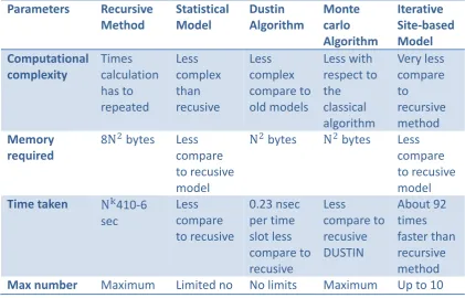
[image:52.595.107.529.499.769.2]algorithms and the relative merits of algorithms and is given in Table 2-1.
Table 2-1 Algorithms used in the normal optical channel models illustrated by
Hranilovic in [15]
Parameters Recursive
Method Statistical Model Dustin Algorithm Monte carlo Algorithm Iterative Site-based Model Computational complexity Times calculation has to repeated Less complex than recusive Less complex compare to old models Less with respect to the classical algorithm Very less compare to recursive method Memory required
8N2 bytes Less compare to recusive model
N2 bytes N2 bytes Less compare to recusive model
Time taken Nk410-6
sec Less compare to recusive 0.23 nsec per time slot less compare to recusive Less compare to recusive DUSTIN About 92 times faster than recursive method
32
of reflection possible
3 bounce of bounces but restricted by emitter power
up to 40 bounce is possible
bounces are possible
Adaptation No No No Yes Yes
Accuracy Very less Less Moderate Moderate Moderate
Published year 1993 1997 1997 1998 2002
A practical optical channel model is described in [16]. The following illustration
[image:53.595.175.472.295.538.2]shows the basic structure of the model.
Figure 2-2 Infrared Channel Model introduced by Barry in [16]
The above model is considered to be one of the most popular optical channel models.
It takes consideration of the angle between transmitter and receiver, the mode
33
In the model described above, S represents the transmitter and R represents the
receiver. ( )R is expressed as below: [16]
1
( ) cos ( )
2
n S n
R P
(2.20)
where n is the mode number of the radiation lobe, which specifies the directionality
of the source, (n+1/2π) ensures that integrating R( ) over the surface of a
hemisphere results in the source power Ps. A mode of n = 1 corresponds to a
traditional Lambertian source. The scalar angle FOV is defined such that a receiver
only detects the light where the angle of incidence is less than FOV. [16]
The impulse response of the system is given below:
(0) 1
( ; , ) cos ( ) ( / ) ( / )
2 n n
h t S R d rect FOV t R c
(2.21)
where d is the solid angle subtended by the differential area of a receiver:
2
cos( ) R/
d A R (2.22)
R is the distance between the transmitter and the receiver where:
S R
R r r (2.23)
is the angle between n
and (
r
S
r
R):cos( ) n r( S rR) /R
(2.24)
is the angle between n
34
cos( ) n r( R rS) /R
(2.25)
The impulse response, h(t), of the model, is as follows:
1 0
1
( ; , ) ( ; , ) * ( ; , )
L
k k R S
i j i l l j
l
h t S R h t S h t R
(2.26)By substituting all the equations above, one has:
( ) ( 1)
2 1
cos ( ) cos( ) 1
( ; , ) (2 / ) ( / ; , )
2
n N
k l k
l
n
h t S R rect h t R c S R A
R
(2.27)It denotes the impulse response of the kth bounce (power distribution). Moreover, the
impulse response of the kth bounce is only related to the (k-1)th and the first impulse
responses. Meanwhile, the formula of the time domain can be transferred into that of
the frequency domain, which helps to estimate the frequency response.
However, the research contains several pending issues to be verified, such as the
shadowing, path loss and interference, etc. Meanwhile the number of source being
employed is the only one, which implies that the MIMO system is not considered in
this model. Finally, the power attenuation is defined as the multipath-induced power
penalty of three bounces from one source.
2.5 Optical Wireless MIMO System
As one of the broadly-known alternative applications, indoor optical wireless
35
especially those presented as the next generation communication due to the high
speed and high security assurance in data transmission, facilitated by a MIMO
system, which enjoys unregulated bandwidth. This section provides an in-depth
discussion and analysis on the design and performance of MIMO system based on a
2X2 infrared OOK modulation and regulated bandwidth at 100kHz, 1MHz and
10MHz.
As having been described by Koonen in [17], the fibre-to-home technology may
facilitate the data transmission rate up to 1Gbps at the home gateway, and has
therefore attracted worldwide attention. However, as further illustrated by Ntogari et
al. in [18], the application access to allocate the high rate data from fibre to customer
device is considered challenging, unless the IR-based communication is of presence
to proceed through the last mile. [19]
The next generation wireless communication system includes a large group of
mutually-complementary technologies. As one of the important compositions, the
indoor infrared communication technology may deliver the expected performance in
the range of 780 – 950nm, and demonstrates many advantages for short distance
transmissions, i.e., infrared emitters and detectors may accomplish high speed
transmissions at much lower costs in comparison with those by radio antenna and
visible light communications; in comparison with the region of radio spectrum, the
infrared spectral region is much broader, and there is no need for licensing approval.
However, infrared light is capable of penetrating through glass materials, but not
walls or other opaque blocks. Consequently, such infrared communication can only
![Figure 2-2 Infrared Channel Model introduced by Barry in [16]](https://thumb-us.123doks.com/thumbv2/123dok_us/9522812.457632/53.595.175.472.295.538/figure-infrared-channel-model-introduced-barry.webp)