A
Presented for the Degree
MASTER OlJf' SCIENCE AND' HOliTOURS in
:PHYSICS.
UNliVERSITY OP' NEW ZEALAND
1955.
Jrl--
~·Canterbury University College
t~rop~.l1os ueed an i:nve~t1sat1M
at
aneo:tl'.:r>ttcn,dootncal
prop$rrt1eaor
c~~·te.ll1ne t.~!l(#$¥Jfl.ot~ of ~ll~nli halidac. ~ottwted b;v fue.r"o :tif:'<..o-toe~JtlduettvitY'1
too
ll<1lpendanee; end asjr¥OJt~tr~,~
llno 3ttsttty the ll£~ t1 ca~~~~Jt~tion~~l
eoo~f.nlilte tnotl~. '11il':lvt81 depend.Emce
ot
pccttt~\ilHiil:§l§
'tQc.
~17 .(:~1 ~~\ (f) 0 (), Q) "0 c c::. {f) en (!) ...c:b
COliTDTS 1\iotaticm. AcknowledgmGnts.THE .UESIUH 0~'
2.1 ~1ethocis.,
2.2 The furnace.
2. 3 Temperature control ..
2.4 liaising mechanism.
2.,5 Annealing mechanism.
2. 6 Crystal growth.
2. 7 Crystal shaping.
CHAPTER III.
3.1 The Photometer.
3. 2 Ul tra.violet sources .. 3.:5 Slit range.
Introduction
Grystal Growth.
The Optical Instrument.
3. 4 Loss of He solution due to finite slits.
3.5 Scattered light.
4.1 The Photometer.
4.2 The Photomultiplier. 4. 3 The d.etecting sy stcun •
the l)etecti.on .ay-stem.
4. 4 The mechanical coherent detector.
4. 5 The electronic coh•rent detector.
4.6 the signal to noise ratio.
4 .•
7.
Comparison with other instrumepta.Ol!.AP!lll "•
J•1
·fhebot
or;ll•s.~ ~e
Am
oe11.
5•'
ftaol\eaoence.
5•4
Pkot01on4uot1vttv.
5.5
Gauetd.ama1:re1e.
VI. l'i:sperimootal
Resulte.
6.1 r~ac.tta:rot~ttd abco~t1on.
6.2
V1b~t1onalBroa4ening.
6.3
Photoeon4uction.
6
.!t.
imiaaton..
6. 5 l!bBOt"ptiotl.
Theory.
7
.-s
Tbe Fhru~-ooruion Ptl*inc:d.ple.7.2 Williams• caleulntioo.
1.3
Omclue1on.
66
69
73
7l~
11
81
83
86
1. Slit
functtonah
89l. 2
'
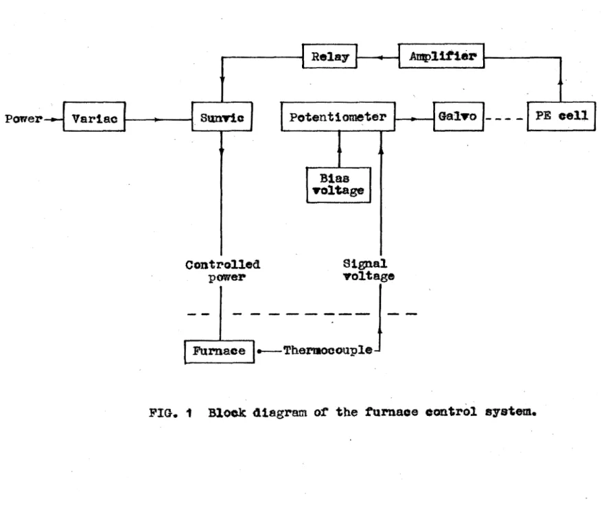
4 !> 6 1 6 g 10 l l 12 1} 14 15 16 17 18 19 20 21 22 23 24 25 26 27 28 29 JQ 31 )2 )3 )4 )5 )6 37 38 39 40 41 42 4)furnace eontrol.~stem. ~oct diag~
Control ~nit. Circuit.
The raisins meehaniem. Photo. the annealing drive. Photo.
SUpport; ball-Joint, chuck and stud.
Front view of the furnace. Photo. Back view of the furna~e. Photo.
Cr,yetal growth. Photo.
Doules. Photo.
Or,ystal pieces. Photo.
Hg-ara and HF6 output. stray light.
Dispersion a.mi alit range.
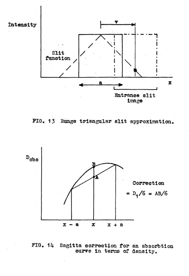
Hunge' slit approximation.
sagitta correction.
Finite slit effect on an absorption maximum.
Finite slit corr~otions. ima.l.;tsis ot' stray light.
Strey light mechanism.
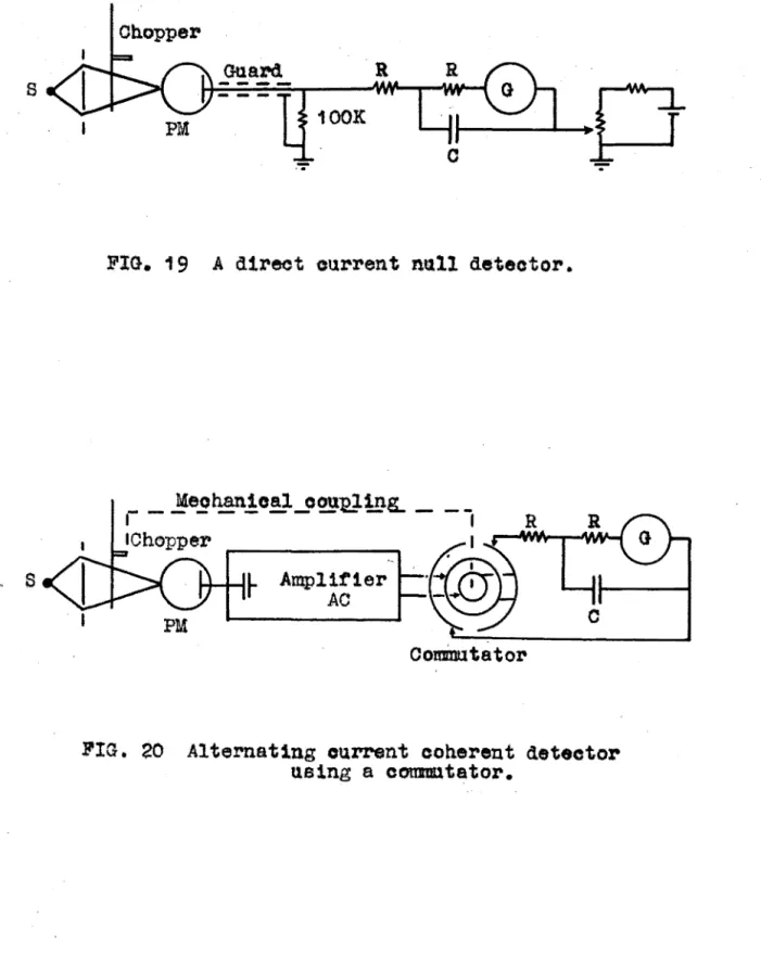
D.O. null a.etection system.
A.O. detector using a commutator.
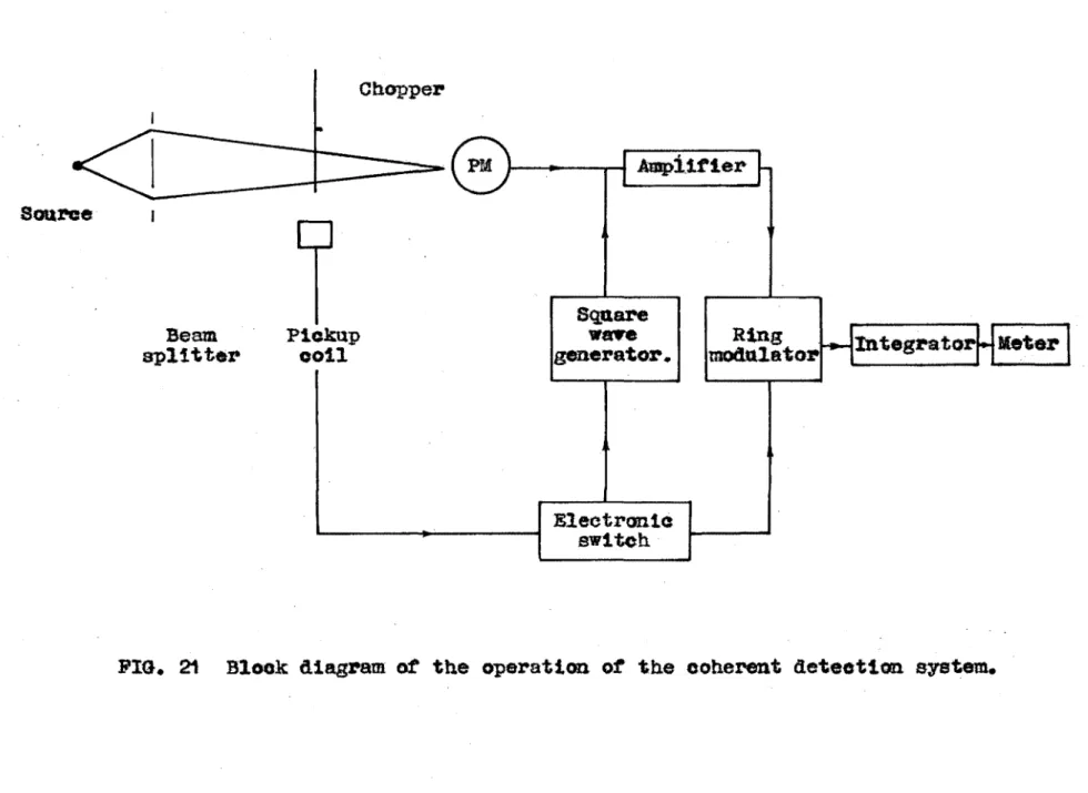
Coherertt aetector. b"'lock diagraln,.
Following.
2.7
•
Chpt.IV.
'*
Detector ~ld square wave generator. Circuit.
Shot noise influence factor.
Assembly :for absorption studies. I)hoto.
Commutator and pickup coil. Photo.
The detector. I•hoto.
The hot cell. Uiagram.
The hot cell nismantleu. F'hoto.
The hot cell assembled. Photo.
Photoconduetion arrangements.
The dark cell. Photo.
Background. Absorption and. ref'lection.
Variation o.f suri"'ace absorption.
Absorption of' thick samples.
Half-width againsttemperatur•. Emission spectrum. KBr:Cl
.Emission spectrum. RbCl: Br
Emission spectrum. Kl: Cl
Absorption spectrum. KCl:Br
Absorption spectrum. HbCl: Br Absorption spectrun1. Na.Cl: I
Absorption spectrum. KBr:l
Absorption spectrum. NaCl:F
5.1
"
Tables
1 2
'
45 6 7 8 9 10 l l 12
l'
Oolour centres in alkali balides •
wavelength calibration. Hg-linea .
R16 stray light ratio.
Ohpt I.
'·2
H.F6 atray light eorx·ection.
PM, current to intensity factor. Emission energies &nd widths. Emission exiatenoe.
Absorption energies a.no. widths. ·
Abaorption and emission. Approximations. Willi~ calaulation.
Gauss cu.rve slit width fur~ctions. Appendix .
Conversion of A to ev. 400Q-7000A Appendix
Conversion of A to
ev.
2000-SOOOA Appenctix.'·'
..
6 .• 57.1 .
7.2
l.
A
AO, DO
B
D,d
e
E
erf'(t) ev, mav
exp1
oY
f ¢ h H.F6 i l IIi K L;l,e m
Alternating, direct current.· Dark current.
Band width in cps.
Optica.l.d.ensity.,.
tideal = {l + e) Y observed
Energy in ev, transition energy.
f'ot
!i {u} duElectron volts, milli -av.
lOY
Phase angle.
Slit range I observed. ·~-width.
Hydrogen arc.
Current.
Intensity or flux.
Infra red.
Kilo - ohms.
Observed. aud ideal -!-width.
afa • Absorption coefficient.
M PM gain, ~egohms.
k*(t} (2TT)-i exp (-t2; 2)
P Time constant.
P{E) Transition probability.
Q.
RO
me
t
'l
uv
v
v
w(t) x,x•
Resistance capacity. Root mean square.
Slit range, a - f'o r a single slit •
. standard deviation.
kt = zero-point energy.
1 1 l -D
Transm sa on
=
0 • Ultraviolet •.Frequency.
Potential..
t erf (t) +
First and second uearest neighbour distances.
Reference to F. Johnson {1951) and D. Johnson (1952)
ACDOWLEOOYENTS
The writer greatlY appreciate• the privilege of working in
tho Physics Department,
c.u.c.,
and in particular the offerof' the late Profe.ssor ll\C. Cbalk.lin !or the writer to
cornmence research work in 1»54.
A debt is f&l t to n'U1unbers ot: start and students tor their
interest and cooperation. In particular, thanks are due to Dr.
a.
'l'.P. Tarrant, iiead of the Department, f'or his counsel; Dr. N.K. Pope for theor·etieal discussions; an.d Mr. A.H.Meilraith for mar~ discussions, both technical, and of the
nature of research.
Considerable help has been received from many people, to
whom the writer e~~ress~s his thanks.
Mr. E.L. Rowe t'or trai:ning in I..a.bora.tory techniques and general assistance.
Mr. E.D. Shipley !or suggesting th~ use of the magnetic
piol<.up device, and the design and. construction of the ring
modulator and electronic switch.
Mr H.G.T. Bennett for design of the square wave generator.
Mr. E.R. Mangin for advice on photographic reproduction, and
in particular the Lindhoff Technika camera, with which the
Mr. L. Heath and Mr. H. Higgs.
ot
the Oant'erbu.rt CollegeIndustrial Devtlopment Department.tor construction o~ the
chuck, commutator, and hot oe11.
Mr. G.D. Green. Chemistry Department,
c.o. c. •
f'orconsiderable cooptu"ation and a~sistanae.
Mr. G.E. Roth, Dominion X-r~ LaboratorJ,!Or the loan of a
Lindemann electrometer, portable pro.jeeto:r and e. high
resistance.
The manuscript b..'l.s been typed and the f'ina.l copies
I
prepared by ~ fiancee. Miss A. Robinson, and by Miss
M. Mitchell. »>lr. R. Wade is responsible for the binding.
Diagrwn reproduction by ):;;;:es:srs G.1: •. v. Pl'"ints Limited, Christchurch.
All ether design and construction. has been perfonned by
:the wri tar.
l''ina.ncial assistance, uuring the course of this work, was
r&ceived in 1954 from a Junior scholarship, and in 1955
studies of' negative halide ion activatea.., alkali
halides begun. by F .. Johnson and D. Johnson are continued. The fixtst stag~ of this problem is completed., a. mechanism . ·
Lhavt.ng been established. A detailed investigation of'
the experimental tecr~ique and results of these workers
is reported.
The following equipment has been built.
1) A furnace and associated control gear, raising an.d
annealing mechanism, fOll:' growth from. the .melt by the
Kyropoulos method. new t~chniq:ua of growth on a. Hickel
stud is described. :3everal bou.les may be growrJ. in ::1 o.ey.
2) A pha:se-sensi tive coheror~t null detector and. constant
amplitude square wave generator fox• use with a ~3pvkker
photometer for absorption nnd intensity measurements. The
detection lb:~i t is lOCO quanta/ sec. Optical densities a.re
ri:lproducible to the nearest (;.002 for densities of 0.2 to
2.0 over the spectral range 2l5c to 6SCOA.
3) A vacuum, hot cell ca.pable o1' maintaining ClfY stal samples
at temperatures up to 0 1'or absorption measurements at
elevated temperatures.
4) A dark cellt'or U$6 in nu.oresesnt and photoconciuctive
stucU.es.
5) A projection system for analysis
or
curves intoA number of calculations .and theoretical derivations nave been made.
1) The calet.ll<J.t1ons ot Brodersen and R\.mge are extended
and simple practical rules deduced to allow tor loss of'
resolution due to finite slits.
2) The error introduced by noise into a d.ensi ty measurement is deduced to r a Spectrophotometer lin1ited by shot noise.
J) A table for. conversion of Ar1gstro.ms to electron volts is given.
Various instrumental techniques and limitations have
,;been investigated.
l) A simple temperature control system is discussed.
2) An investigation of Ultraviolet sources shows the
superiority of a hydrogen discharge fo~absorption
uiea.surements.
3) Prism instrument~•. using a priSin with a ground base,
produce ~l. stray light background r~t a leve.l of' 10- ' ..
4) Commutators in coherent detectors a.re unreliable.
J\ repetition of' the Johnsonst work and studies of
background absorption. vibrationAl broadening. photoconduction,
fluorescence, absorption and line shape. shows that the
Dt• ~.tl11arns theory. oommero1al uae of phoapbors. nand theory rnodel. (}onfigurational oo•ortiinate
model. Crystal imperf({Otions. !i~ed f'o~ study
of single crystals of both 1on1c andnon-ionic
types, Colotn·· centres, 'rE:ible ( 1 ). ·
Need for more extensive theoretical calculations. work of F. Johnson and J. Johnson. Chalklin*s reoornmenrJn. t ionE~.
spent.
In Apr111 1951, Dl' Fevd Vtilliamn publtened the det~1ls
ot
the first calcul at ton,tram
ttrat pr1no1plee,ot
abso~ption and luminescent spectra in a crystal pbQOpbO~•
fbi a paper probably llank:s anong the most impottant eontribu ....
tiona to the theory of solidB it4 the lnst 20 years, bc:tns tb~
first step aw~y from a purel~ phenomenological
theory.
Intet•ent 1n pbospbors steme from the insight provtd~;;d
into elect:ronic processes and their rapidly increasing
commercial use {Leverenz 19.50).. As a tool phosphors have
the double advantage of the ability to e:rfeat an eff'1cient
d1 reet conversion of a prtmax•y eici tat1on r-anging from 1 to over 1o1ev into visible photons; the ability to sto~e
potential radietion energy f'or tirnes of 1o-7 to over 101 tHlO•
In day to flay use they are found in fluorescent lampa
-200,000 Kg I y~ar, eleetrolur,'lineseen t la.-nps, t Glevi eion ~;,nd
radar cathode ray tubes - 1
oo,
000 l:.t.Jot
phosphor• tHH~d (it.a:•ingWorld ar II, x-ray se!'eens, infra-red image ;;.H:mvcrtor:::,
light fluorescent postevs saint1llat1on countera.
Special applications are found ~1s flow 1nd1c.H'lltcu•s, tempcr£iltUI<e indicators, cascade transfonnera, using contrast compression
w1 th. t•n phosphors tot' solar obr:.erve.t1ons in the ictu."ooeopG,
and as time delays for storing 1nfor-m:::.tion and controlling·
electron~.c timing ueviees.
convenient and £;:Ems1 tive indi<.H~tor of' changes
ot
corr.tposit1on•structu~e and atomic interactions that further research will
) • ·:t1ll1sms ( 1
pertodto lattice potential.
aonduato%' one thef!le b
Hettle~ - 1n
tr-on ita
posit
the lattice ~re not involved,
applicable.
fhe conr
etectronto
tionplus
ttiog in thtl' reerrangc:nemt.t
t1on the oo-ord1noteg
or
th~ c~tro by a single ao-ordtnst~.eru~traN eg~d.n5t eo-or-•1inBte contours oan be oorwtruoted. Absorptton aonmir;te of a ti.on
,.
A redtetributton
ot
electronic charge follows, ~educing thesystem to a new equilibrium J>OSition... o:f'..._. minimum ener , th. e
excess ener-gy being propoga;-ed as ela:SvlO \vavee. Bf.U.Oft
occurs, maintaining the atomic nontiguration. $n4 anotbar
ment energy as the difference in E~xci tat ion ·tm.til.
enere3t that ~ torni~ cord'1gurat1one ot bcrr than that. of lGlli'feat
energy have finite probab111 ties, producing t
tention to iict
reat'rangemente arHl radlationleas pro~c1ssee.
rrne history of the onderstnn:U of the p tiot; of
(1953), the ~anroaaopia a
cul n 0
s.vmmetr;l, the umleratentiing
by crystal lattices. the analysis of the behaviouz~ of atoms
and particularly the valence electrons in perteet crystals,
achieving its l1mi t in the analysis ionic crystals bJ
Madelung and born. l'he fourth and pJi'esent pbasc centre~ ~i~bout those phenome:na which cnn he explained only in terms
ot imperfections.
,.n att t to regard the varioug types
imperf'ections f:t:•om a uniform viewpoint haa be n
Seitz ( 1952). 'rhere are six types of primary tiona;
phonone, eleatt"ons and boles, exci tons, vacant lo..t tice tes
atoms, and d1sloaat1ona.
ln
audition the~e are threeIt is at~eased that the
1nteract1ons of these imperfect should b.fi
an essenti
imperfect;ions are not independent of' one anothev.
~ance the majoFlty of 1nort,:~an11} phomphore
e only in the
OCm'l!iJOt"Oi (;ll
of
microcrystalline
,
Gat,.lio:t:~ (1 J hasneed !'or study Of phosphore avail in, ttH;; 1
singl~ cn•:v·ate.l s. l~hUfilt i i htlVC I'
consi 1e
tbeoret1 1ci t,y. the
suthrtmtage that the bowl is destt"'oyecl 'When
rm electron is ejected f'rom an ani on, or supplied to u
cation. 'fbe offr,cted atoms may be irreversibly d ispleeed and du:r.1ng an experiment the original oimple crystal becomes
increasingly complex. This ie often the aaae wltb high
therefore t'ilso urges studies
comronents in tbeir bonding energies.
icity of alkali halia e in ionia blnll 1 ic
structure, t1nd binary composition is ln. contrast to tho
increasing variety of colour centre poonemena - ei t~ 1 •
1954. Vaaanciee and vacancy clusters play a prominent role
.-aoancies, nesat1ve lon vaoane1~~, eouplf:d palrBS
or oppoeite m1~n, a sobstitutiouul d1VIlii1ent lOll as1:5oc
with !!l poe1t1ve ton vaoaner, mrw a. negative:~ ion vaosno,v.
phenomena
dtecua3e4
· whosetbc:uui/abeorpt 1 OEl flr-1
the
(!; (1).
ie by
to be so ide 1rl the
eontra pbenor1wma• nnd to
in thie department.
~.:._,I
1
o( ~ 5·1 .l
c:( , 6.11
nigh enc.1trgy band o!' nn F om:re:rce ..
ton to
i
5 •
1:11' a entre ..
R2 centt'e.
A,B bands.
li centres.
negat1va ion vao~nc1 • de Boer m04$l. From addition of exees& metal to • bal14e
followed bJ quenctling, or ionising
Pad1at1ons, ~'hen other banda alao appear;
Chat"ect'er1$t1c
ot
the c:n.~tyst&l.f not of metal v&pour used.I~ar:i'
KF
L101 .t~~lOl 1\0l ltbOl OsCl 3.63 2.73 .).20 2.64 2.19 2.00 2.03Nf*Ht" .W:~r R1~13t~ .t:I h:bl
2.29 1. 98 ;.n:; 1 f'>e'<
• vv 1.60
6;.
of vaaancies occurs ot 1t52ev in KJl, 1.12 in
Na;l, 1. 90 in 1,101• ~"rom 1on1~aticm of an F
eentre b¥ F- light at ~oom temperature Gnd
tr~naport of the vacancy thus formed. 'rb.is
also produces H11r,~2 A,:~,l~ bands in the neap IR.
One oxcesa electron near two negative ton .
vaoaneiea.
f's1r of' bound F centres. ~xiotence still in doubt.
ii band.
Tl centres.
U band.
scott, Smith nnd ThOOlPSOn (1953).
AntimoPpn
ot
1'' ·otmtl'~~e, hole and posit! veton
vaeaney.·
radi tion - as are othm- V bands.
above -1
oooo.
Unstabl-e
•:rt~vo post tivo ion vacancies with one holG,
analogous to };1 centre. ~'12, V 3 obsm:ved by Mollwo in ar-yetsle containing e.:-i•.1ess huloccm..
two positive ion vaoonaies with ttYO hol.os,
analogous to centro.,
,;,,1ee bani sm t:nlcc ert aith
{1951).
~eaults by ~orcndort
naol
KCl
y.,,
,.;I
V bands at liquid belium temperatures. Configuration co-ordinate model.
theory by lt\fllia"lls {1951a).
Il
{ 1952) .. substitutional
Er,
U•light below -1oooo proauaes an IX band. KOl 6.,741a •.
])ival.ent halides ln. a.l.k$l1haltaee.,·Dtscovettsd
~ixect eJstema. studte~
ot
¥1v centres 1n
srsttJmsot
tot•r~· Halogen ion
cent .. es.
MX: MX:toc:. I:'ioneer wo~k by tln~u~cUr.<~IEJ:%1'
(1953).
John.$on ( 1 951 ) • abnol"'ptton due to exoi tan lev
f
u. Johnson ( 1 t
4. 82, 4. 5.3(
c.
21); 4. 85, 4. 67{c.
30)~£1der { 1955). rlorm
ot
temperature dependence,line shape, an1se1on, ae:rcr photooonducttv1t7•
aoo aoublet at~uoture1 sb.owa valldi t7 of
further interactions and pttenomena 1a rathe~ 111te building e. house on aand.
la t t to ttll libr~n,tes wi tb pa.rt1all~1' undigested
tacteJ
surel7 1 t 1a to inoreese ou~ knowledge and unde~otandtng
ot
baste principles.
'
many
ot
the explanations anu m~chanisma of' appa:t""entl.y wellphosphor phenomena.
tor nearly thirty years.
novel or ditficul t in his c~J.eulrltion .. i ad
J.ct us
hope thriilt future rforke:rs 'vill fol1ow in ;:~r, ~.111i~l:sm f'ootr';,teps. The work performed 1n this depat .. trnent sprang from the
need fo1~ detailed study of simplG crystal systems"' Alkali
hal1dea containirig negative halogen ions were chosen a~ a
tool.
in the last section of Table (1) .. P. Johnson d!soove~ed the
abeoroptlon peaks in NaOl:li', l:~e.~'\t•:Cl, NaCl:Brt Naol=I-,
obtained the absorption energies, made an empirical calculation
10.
tbeGe leVOlf!J '\f1 tb 8ltC1 ten levela fO:rnted bJ' iti.OO~Ol'Qtin;&
tbe
lt wea tnaggeat•
with tb$ doublet ground states of' th0 rm.l.lde ior.m,
the shift
or
penk abeorpt1tm to lower er1erg1ea ''mstxtom that cr Dr. l''er>d ~a111sms :t'or
obtained the sbso:rpt1on enet'gy for
.
"It 1& the
•
and di
i.nted out tbe simi
ion with those
d:Hi nnt ance the subject.
assoetate«
1 the
time he was my Bupervisor he was Bape:;cially oletn." on two points.
F1rstly11 that a thorough enalyaio be; made
or
the experimentaltecb.n1qua t
~"rom the beginning 1 t w~aH:l r that f:ll
e.xperimentol ~na theoretical 1nvest1gnt1on of the
more than eoul~l reasonably be
expected of an M., :·;c. student.
in the
'throughout the
been on the anslJe1e,
design.eonstruetion, and tcating of
1.f.
Department will be able to proceed ,aa (!Uiekly sri.\\ ettioient.., 1; • posatble. lt;tuipmen:t been bu1l t to a.llow et~ut.H.es
ot
cpysta.l g~owtb, annealing proeeaaes, al::ulorpt ion and ent1aston spectra, pbotooooouotion,
llnd
the
efte~taot
temperatur~on
the spectra. aeverel crystale oa.n be gttown ln one day and their properties meal).nJ~eti the ne:xt. ln. the couX"aG of this
development,
however~, sufficient r~eulta havebeen
obtatnetl to establish the nature of' tbe eleebtonics rnecbantam, and atpt'esent a paper is being pr-Bp~ed for publication. I~ 1a
described will help ou-r ultimate understmlding
procease~.
·work in this
period of 44 • 1 nvol vir..e
Februar:. April to :\ugust,
March to June.
Methode.
ture. control ..
Seed crystal.
shaping.
Polishing.
technique.
12.
Operation. Block ~m.o tackle
{ 2. 1) O!YS'ri~J. GSOW!li.
U$eable e~;vstals of convenient s1~e are us1.ura.lly
from tbe melt• by vat"ious techniques ·many
ot
wbi~b ~otiiecueeed bt '~erfoee, Johnson anrl ( 1949).
1) 'l'be moving crucible metho!l
ot
J:!r.tdgman. A cruciblecontatntng
tbemelt
lalowered
through a fixed
thermal gradient.
2) The atationary oruaible
A erucihle eontt1.ining the melt is cooled in a slowly
changing ther•m;::~l gradient.
3) The b:Y'flopoulos technique of' drawing a seed from the melt.
4) r~utectte melt growth. relying on special properties a
low temperate phmse.
5) The Verneu11
oxyhydrogen torch is collceted as a molten drop on a t>efactory rod.
6) Growth from the vapour phase.
mater 1al io
All but (lt.) (5) or (6) could be use:1d with eonvcnionoe for
the growth of alkali halides. hniQue (7)
espeatall,v promising. It vtas not investigated since
built b1 Johnson F {,36) existed rot< m:thod (1). It
capable or producing opt1eully excellent crystals
very gret\lt advantages. Firstly the technique is vr'r·y simple,
work involving 1mpur1 ties no J~tet-rdns:t1on or the 1mptn•1ty
content would be neeeaea~y stnoe all the impurity will Investigation of this technique woold be very Vt~lusblra.
Johnson F {37) chose the ~ridgman method bcesuee
tt
ta
automatic. '!'his ia 1 til& main tU.sadvantage, 1 t ia too
automatic. one has to watt a week to know whetbe:t* a
s~tta-factory crystal has grown o~ not. or the crucible baa leaked.
It
the crystal is unautisfactory it is necessary to startagain. tn the method to be described a useable erystal can
be g!'O\'Hl in 4 hours and the f'urnaec ready to gz~()W another. Techniques ( ·1;; \2) {3) a.t·~J in principle tndonticr:il for
crystal. Choice between them rests on the tecbnolo£;1Cal
ease of £H.lpplying the condi tiona suit;;l:lle fot• ;:::rowtb. ;Jtrong
(1930) summarizing the experience of mana worker•s l'lf3ts fiva
condi tiona which ensure growth.
1) Cttrstallization must stsrt at a e1ngle point. other•wi~S()
the oryetal may be multicryatalllne.
salt. 'this helps orientation and prevents twinning.
J) Temperature iaothermals within the crucible should be as nearly horizontal as possible to prevent convection
rclat1.<ve to the crystal e.l.c;nvly and uniformly so that tb~
C:t?ystf\11 latd down at this ~Jurtace will be aouna
ooa
flawl.eas.
4)
the crystal has been foPme4 the bottom and topot
the cu'tystal muet be brought to the same temperature to avoid strains.During
g~owththe
cr3stalts
in athettmal gradient of about 2000/cm, end i t the padtent ta pl'e&erved ae the temperature 1e lowet-ed, sa in the
Johnson technique, considerable strains will be set up
due to the un~ tempet"':clture.
cooling ~atee- especially near room
plaatla eo that immediate
gt~owth pr•oduct:;a no strain ..
alkali halides are fah"lY of the i
5) The crystal must be remove{l from its eontminm: or
holder before cooli
contraction of the holder.
A comparison of the :Kyropouloe
given by )., rhe
outotrmd1ng-t!tt1vantaDcs
or
the hyropoulos method are ease of' ientcontrol the proce£~s oan be interrupted during growth. io
'!'be existing equipment was rebuilt to allow growth by tbe
!~yropoalos method, but the lO\'Wering meohanism used by
Johnson for
the Bridgman method canbe
easily attachedit
required.
Tbe fUrnace
and controlgear were made to be
ver-satile as it \vas hoped to perform studies
ot
the annealing process and the possibility of using the techniquetor
16 •.
The fut-nnee need not be as
large as
it1&.
~H.n.ce heat loss 1s proportion$! to area, the power to he
contx-olled vatt1ee as th~ square
ct
a 1i3Plcal line~ d!menaton.Oructblea used by paat workers und aur1ng tbe p~e.sent wottk
were 2 ... t.n tU.ameter or lees whereas tbe internell 41ametev
or
convenient.
been entirely recOn$tructed, \vben it was reall~ed, evident!¥
not by Johnson that useable crystals ue be only 1 1 mm
in section, fot• this is the
Spekker .Photometer where the
{2. 3)
providing both proportional
controller, for t;he \vork to
ttJOUffh two 1nuepen.dont cizleui ts
integral re~ponGe control,
ted from a mirror galvono.:."!leter:•, placed 1n a
potentio-meter cit>ot.li t w1 th the thermocouple, was either incident on a
photocell or not,
dependent on
tbe galvonomet~ indicatingabove or below balantje.
a sunvic connected ~ resistance into or out of the tux-nace
mupply e1rcuit, Figure {2). !n tbo p~ev1oue wot-k the
thermo-couples were merely dangled in t;he radiation field of tbe
furnace, an11 with the above simple contx-oller control was
inadequate, evidently due to the poor ei'ficiencv or radiation
tvansfer to the t hemocoupla/1n a ceramic bloelt, supporting
the e.rucible, when the thet-mal contact. ot: f'u)'\nac:e wall anti tbevmocot.tpl~ is goo4, the simple c-ontroller wa.s totUtd to
Xt would
servo-mechantam to bave only one aont~olling time constant,
and a1nce tbe controller delay cannot be removed tbe rurntloe
be assisted it the fu:rnaoe were ennallel"•
In tiee 1 t has been found &ut*f'ioient to place tho
the CPUCible 1n the lniddle Of the
to switch on botb heaters till the salt melted; start the
controller €md swi tab off the hot tom heater. Both tbe
elaborate simple controle su one disadvantage.
that neeeesery
tor
the contl"oller to sw1 tch on tho power - due to a temporary
were re:zAd to 1°0 on a Cambridge un1p1vot 0-10
m1oroamp
meteror by watching the galvanometer spot.
It ("!ppear that occur ove1,. a range grt~a tel' than 1 - 25mrn/hour (
wi tb optimum ratee> of }mm/hour t'or pure halides.
tb
1947)
Jtange o:r epoedg is gi van bN a mechanism using the bloek r.md
40 t•ph synchronous motor ivee tbe 40 : 1 worm tached to an u J1. ";., screw.
ball bee.ring pulley and
a ol ?1re fixed to the moving block and the baeo plato.
18.
complete
oiJ:'icUitor
cbor-4 around
tbeti:ced pulleg
theraising
rate 1n nnn/hOur is tbe numbei'
ot
1loop$'• · •A m1orosw1toll on tbft beme pltlte,operat.~a by tbe moving bloc:t,entcheG a
changeover relt13 wnioh tYI1tcbes
ott
the raialng· motor aM1s px-ovtd~d and varioua olamps to flllotv
cbange ot
the nu.mbe~ot
loops. 'the ~ai Bing meehanism WtUil not UiUtd ·ve~9often._
Menstes
(1952)
points out that e1ncethe
soli4 is aent~Jel*than
the liquid the level in the cr-uoibl.e automattoal17 falls.
Tbts is
v~ry eonven1ent.a 1 ~ 10 on a j" ~:\luminium
disc th :l?b1s disc l"uns on t:\htJ.ft
attaahecl to a Ol1L'1l ~·1 rewound. ontiomcter t~ (.t
firmly attached to th1s sbaft ~'IH:'!rew1ng up the
•
tch' nutwhich rorot:~s a cono~ntrtc oylindet- to bco.r on the distH~. .'hen
in c trout t the meahar.risrn will lower the fux-ma.oe temperatura
Iii th this
stud on 1-vhioh it grew and placed in a preheated box of
workers - pl&tintF', silica e:;ltru.u~, fJ('Jraoluin, iron.
Vitreous ai 11aa has be!f:·n found ccn:tv,:"rlient proviuc.::l that r:t!'tcr
it aoola, el~e it adberea ta the silico ond the crucible
8aah arucihleo are readily cleaned by heating or'
soaking in watar.
a
the cooli nq; mea hani Hm if.::J Pl"'ovt JeJ.I by nickel coated
braes chuck with eaoy-flow joints, and water cooled;
u;i (·r::)
" gure ::; •
of' u s.e. cc
in coolin~ the chuck. No~nally it is run at
One of the erporent difficulties of the tyroJoulos
method is the need for a eeed crystnl.
stittable piece from the solid maee.
method.
is however 0U1cker to proceed ns helow.
evidently tried growth directly on to platinum.
shaped nickel studs were fitted into the end of the chuck.
diameter bas been grown at tbe rate
or
1Ocov"hour..
11\ elmpleanalysis 1 1 thst a rough gu1 is, length
·or
crystal. ·time ..
and Miller (1 )
give man~ practit~sl details the t'abrieH tion of 1
ba11des. The ele~lvage planes Mt'e ~c:adily found. by t•;stther
quickly foroing a corner of e on to t
rough gri 1 gri excellent.
thie fJOint and tht"J
Jd in
ar1 t:lr imrry ar~n scraper Eiven t~ light tap, rcecHiil.)t cleaves
the crystals. Ther-e may t:a some auvantage to this
under water or parafin. The aurtace oharaaterlstlaa
or
allsuch crystals inelur.Ung some ceen in othet- laboratories are
rather veviable due to many .fine lines on the sur-:race.
Hence throoghout thi(') work e11 stn"'rnces have been poliehed
1mmedietely l;r::fore measuremento,. of &bfaorptton.
(Jccasionall,y flhen only ~a small boule 1s g.t"own i. t is more convenient to grind a piece t.o shape ratf'wr•
it.
run
at top speed nnd ater moist Co to
expeotation therHt crystals may be handleq Quite roughly. nnd
21.
lathe cbuol't. an4 kept wet... tbi.s requiree e~re. but would be ..
reatltly done it a diamond tmpl~iiJrt.;~nated t\1teel disc
ot .
sitnil.m:< thickness were ti!Vsileble.t•otisbing is. per-formed 1n two S!t&gee. A grinding
blank !a prepat>etl b1 grindi between two pteoen- of Jillate
glass a
drop
ot watar and a trace of 600emery.
wa.sbed ana. dry one breathes. on the r;t~ot.ula surface
pollcsbing, soon tis the pl,;-;1,te to tee:'l
tn.~ystal it"> 1d;:ly slid otr the plate olean~d.
begin a teky tbe
ionfl the cryt.:ifa:tl tlii.U'"faee will he 1 olean
ruhbe~~ 11.i{htly and quickly on a soft cotton cloth
tightly stretched over a pieaa of glass moistened
with a trace of aleohol. iJrhia produees uniformly optiOf:ll.ly
excellent st.n•f'&oer;, in a vel"'l/ short time. If the rm~ttace should deteriorrite 1 t only is neeeesary to ~erub 1 t on the cloth.
A tectm 1que pointed out by >lowinski ( 1954) tres eonsider~::~bly a~o~e 11 but produces slightlv b~tt(t;:r ii:&tJI'facH:'li'h
After- the oryntal b.a!.?l t.HJ~m rough gt•ound on the aaa
grinder 1 t ia rubbed on a 1D1 lap ~ligbtlg moi with
brine. The f'inal polish is given tb ·the lap bal"ely
motetened with water.
I
I
R;l~7f
•I
k;iifi;~
I
I
Power...t Variac 1 ~ 1
sane
controlled
power
Potentiometer I • I GalYO
J---
-J
PE cellBtas Yoltage
Signal Yoltage
Furnace 1 -Thermocouple
40
fJ4o
Variac
X Neon ... 6.3v
::Q
u
ron_.__
1
. 1
3534
100K 50X '::'
!HE RAISn~ ~ORANI~.
Thia is
desc~ibed tn tlle text. I~cmt thelett la the f4UtO'ttlatic contfl'o1, mtc71!"omt1 tcb
and ~~al
control.
La1
sha~ts ·ar~of
stlve~FIG. 4 THE ANREALING iliECHA.NISM. This 1s
described in the text,. Clutch nut and 1:-..nob
are on the right ot the panlll,the top of which
FIG" 5
and Bnll-jo1nt
the Support,
B
=
B:ron.zeB
Ohnok: Nickel
coated ..
0
Bt11d (N1)SQJ\LE 1 :1
cooled
Ohuck,
; and
position .. t
E
=
IUteotio weld - take apart here.0 = Oil-well
FIG. 6
On the left is the raising mecbani•. the ebuck,
stud and thermocouple are in position on the
centre of the furnace, but the 111um1nat1r~ lamp
is swung up. as is the viewir~ mirror, seen
behind the chuck. The lower unit ot the
controller is the power unit and the upper the
controller prope~ Leads to the gaJ.vonometer and
photo cell run above the sink, whEU:'e thermometers are
placed to measure the :l.nnow u.nd. e.xflow water
FIG. 1 Rear view of FUilNAC.E an.d. CONTROLLER.
the aru1ealing drive may be seen to the left rear
of the su.nvies. in the lower unit of the controller.
li'IG. 8 CRYSTAL GRO~ttH. A photograph taken in
the viewing mirror near the completion
or
growthot' :ar- in KCl. .Dimensions are approximately full
si~e. The glow of the fu mace ean be seen between
the ceramic block and. the furnace wall. The ehuek
supf~ort shaft - uirect image - is out of focus ..
Notice. that by achieving radially syMetrical
heating and cooling, as suggested by Menzies, no
raising is required.· In the J!'igu:re rau.ial. growth
FlO. 9 Nickel studs and some sample boules.
Notice the multicrystalline nature, composed of
OHAPl'lSR III
Flux attenuator.
lble procedures
or
position.
Ultraviolet oourcee. Difficulty ot achieving
i1 i ty. ious eourcen.
intensity. lapge intensity change acrose the
spectrum"
phosphor.
311 t range.
lamp for calibration.
Optimurn sl:t t set tinge. spersion.
ita.
Brodersen•s calculation.
~~ 1 t 1
r
",(. ,.,
'
lt.r .. ppr>ox ma . on rom ~ .• ro ... eFsE'm t1 reau ..
Use of a
Resolving
2 '") 2
principle. ·
=
1' + a • Modiftcat ofRunge's work. i
ti.on
Scattered light. Tests. :rements. with gla:::a slah.
Spectral analysis of stray.light. Triple reflection
scattering mechanism. 'd~nergy argument.
t;.1) ·rm~ .PUO'rOMl/r;i~It. This unit is briefly described by
F. Johnson (,58). It is, however, theheart
ot
themeasurements and several important factors will be mentioned.
?he flux attemuator of the ~}peldtev Photometer, pl.aaed ·
1mmedhttely behind the Fresnel llhomb beam splitter, consists
of a fixed upper aperture of width
o.soo
em, and a variable lower aper ture fed by a $Crew of pitch 16 thread~omtcarrying at ita lower end an aluminium cylinder, attaohe4 to
which ia a sleeve, calibrated 1 n terms of dens1 ty log A •j,p,., )1\. •
1 */1
=
A'f,s.d
=
log10 1'/1t~ dem:!ii ty N·odirlL~ invo1Vei:1 four t;.lOurees of' err·or ..
cirele was sot into the dPum cylinder with a turned \vooden
plug.
the position of the moveable slit, with a Pye travelling
microscope, of quoted accuracy better then o.0005cm, and
found to be a linear fUnction of the circle setting.
(2) The d - calibrations may not be consistent. Here, oa1nt;!_
~,.,
function of d.
error in reading the d- sctale.
(3) i'he screw may be tneorreotly zel!'oed at an aperture
A =A' + a.
(la.) The d!*um sleeve has be~:n ~l1epl.aced b7 a q revs wtth
referenoe to the above false origin,
t..~easuring Q revs, around the sleevE'! from d •
o,
thetrue drum: reading
a -
log (1-
f ( •
q)}
= log h '/~t ss calibrated by the
Thetrue density, hov.-ever ,) =log {r:~• +a) /a
and
'• D : R + log (1 + t \ I
=
e
(1 - 1 ) since it is measur Substituting inD
=
lo~t:: ( 1 + a/ ;,• ) - log ( 1 o-d +1
rl,)\;hf·n f'ixirl{i the sleeve to tbt~ drum ther•e are two possible
( 1 ) 4(d
=
o) = A' using a travelling microscope.,requires t'11emantling the photometer, and is tricky to aet to
· better than • 001 em. In ( 1) 1!' both D1 d :::: o there remains
l&t>ge d.
(2) Close apet•ture - light t~inger pressure, - 1. e., D = co
and the erro~ term is a conetant.
ft):r 1 ( d t= 0)
,=
1 •u =a
+ log (1 +a/A') l/I'
25. ModifYing
thl,.
toallow
In adjusting the lemp, d is a~t to o, ax1d the ltiunp adjusted till
'1J = o; i.e., I'/1' • {1 + tJ/A1} .... with thia piJoeedure n/A' is
c. o1 - gt v1ng
:o
=
dj to an aecu:racy set by the aarevt and thamaker'& calibration.
1a accuPJlte this p~ooeu1ure is rel1af.:~le with an e1'lz."o~ less tnan
that of reading the
a -
sc:t.lle.tho i tton is otwiticf:l.l, e~pee1ally in a VeJ:>tical
dir.:NJtion ·when r::.m 0.1 rmn shift ehangea the dene1tu b;r o.OL;t,
due to t h.;, N:'if-11 d 1'11 v er•gen.ce .from parallel1 sm of · the tv:o bC{clmB
m'il the t4C)t:t:roe moves ott' the axis of' the instrument. e:.tnd the consequent mo:t~e rapirl vignetting
ot
one beam thax1 the othett.'rhe transverse fmd longti tudinal poai tiona ar-e 5 and 50 t1mes
less cri tioal.
suppor-t.
(3 •. 2) ULftAV!Ol,Jfo)f aOUROBS •.
It is known tbat the two previous work$N~ ~perienoe4 oonsldet-$bl~ d1ft1culty in eotd:eving atab111t1 and roelia•
b111 t; in their meu.s;ur.ements, as was tb.e ease wi tb ·Macr)onal¢1
( 1953), (un .. eoord(1d). ·~\s 1s pointed out els~wbet"a; these d1ftic~lt1ea cent~e $round;
1) The u·ae
ot
ao.c.·
~easu:ring technique.2) I~w Pf• are output, and the predominating influence
ot.
3) Cone1dert~ble str~:w light with the llg- source, and
random intensity variations.
Johnson F (65), vli1th reference to tbe Hg- at>c1 implies that
the method used h~d cuffioient sensitivity only on an
emission line, ana in fact hie ro('~asurentents w-eroe msu!e
photographically. In using- an Hli'6 J·o~naon
n
(49) al2mits.
the need for wide ali ts, Hence an. investigation of var>iOtls
t '}400' t •.
sourcaa was run . a ~ n.
1) A h.ydrog(~n lnmr,.), type HF6, though stablE.~ hact lo1f; in.tenai ty.
2) An ot~dinary D.(;;. aro had fair intensity at an arc current
of
5
amp. The arc waa unstable and wandered over tbecarbons. A perpendicular ar•rane~oment of the eaPbon.n
was used so a~ not to obstruct the red1atton from tha
poaitive crate~.
3) J1. bo:~ type l!!t8 lamp, 250 h' Hg•are was convenient. hatl
reasontible output, hut the arc wandered.
tntensf.ty carbons (6
m.m.)
t~ae s1m11~~ tc the o!"d1nary arctor
<U.tl'l'eta belov11,;
OPt Above 15 amp the reQ.i.ationln.ot"eaaed
con&idettably bothat 2400
A and alsotn
perpendicular· carbon arrar~.gement eaused the pos1tlve tJ~u .. bon
to erntet .. 41agonally, and. mo~t of the t-adtat1on was
lost.
'!'be burnitlg rate became alal'm1ngl.N' nigh above 1' amp.
5} Tungsten eleott-odes gave high 1ntena1t1 w1 th
a
carttentot 3 amp. However, the· a~c was very unstable and would not born for more than a minute. at a time. !be posttive
electrode burned rather quicklY and.oloude ot tungsten oxtde
7)
A tungsten ive and a e positive gsv a fairlyhigh intensity and reasonably stable arc which run :ror
several minu vd. thout ad~ustraent. l"tmgsten oxi wnn
still troublesome but n.ot nearly as as before.
From these testa the fl.g-are would rttppear superior> f'rom
the point or view of intenei ty and oow-enien.ce, as the nir
operat at~cts are trick1 to use and um:oeliable. work
in the - 250~1 A region a tungsten source enelosc;:l in an
inert &tmosphet .. e WOUld be WO!"tby Of investigation. All
auoh sources. howeve~. have the grave difficulty of large
intensity variation across the spectrum enhancing stray
28.
shown:
, · A nun:iber of other..- ~Jx'U~ weJ:~~e 1nvett1sate4 an4 tbt
.
·
was
.
4ttohavse tube
tPom
a 160 blended t¥Pe & lampjtoontl \Obe most
eon.ventmt
tor
wa:velength ca11bration, WStb lineaat;
fABI,.E
a
;zzo
5!&1 49924J.2$
4080 '4:.9!17 ,3J!t2 3~2 J.Q.g6 2.2§.72925
2699
2!2!\2643 2537
24&4-with the fluorescent eye piece eal:tbration.
2.§.24
2464
3906.
Ji20
3390
280S
-.
2.!22.
2400 2380
.\.
Tb.e use of a phoepbor. Wt:H'~ considered us a me ana
ot
Since an
interrupted light bea~ 1e used, the phoapbor decay time
to be short, so th.~t a 40 cps equa.re waV'e would be trnnemitted with litt loan. Z1nc ~ulphide has a high conversion
efficiency '~JUt e.:litcessi ve decay time. V~1oua oils an4
vaeelines were tried, and although their decay times appea:red
short
enough theirconversion etflc:tenctea wett-e ·eo low tb.at
losa ot output resulted.
It
wouldappeax-.that sodium
salicylate applied to
the
bNdtseolving
tnMetbVl alcohol
: would be wortbf of investigation since 1 t bas the advantageot
oonatant quantum etttelenc.v 1000 .... 3000 A. - ~~atanable0
·5=
/.
5\
I
(\J
(3.3) SLlf RANGE.
throughout the experimental wo~k entrance and ex1
t
$11 tehave been set the same • the optimum position •. Fort
tt
theSlit Widths are a,.b the energy reaching the cffctor· varieS Q.Q
ab,and the slit range as a+ b • If ab is constant, a + b
•
is a minimum for a
=
b. This was veritied by traversing tbebroadened Rg-line 4050A. The variation
ot
I'esolution fortb < a < 2b is small.
Brodersen { 19.54) shows that. a quantity conveniently
describing the actual resolving power of a monochromator is
the effective slit range Se related to the minimum value ot:
Se, So = Bo ( v) a quantity eha:t"acteristic of' the monochromator,
and ag the geometrical slit range by Be2
=
so2 +The optimum slit width is of the order J...f/a where f is
the focal length of the collimato~ mirror and a is the width
of the beam leaving the prism, Forsythe
(1937).
For theHilger UV monochromator a
>
o. 5em, f is 27.5em. Hence, forA. - 3000 A, this is less than
o.
01·· mm, whereas the workreport-ed here is with slit widths 1o-20 times greater, so
s
0 can be neglected and Se=
Sg =s
say.The A scale of the Hilger instrument has been checked
agtnst the Hg-aro and found to be accurate to about 1A from
2000-4000 A. Hence, take the calibrated A. -sleeve as
correct and use it to·caloulate the angular dispersion
d9/dA Figure (12); giving the slit range for 2 equal slits
Hartmann's formula ma, be written
•
••
and
•
•
•n
=
n
+ o(E~1-Eo-1)-1dn
=
OEaI
(E-Eo) 2n
odx
=
rg.
~·
dE dE = K (E - E0 )2100
so
10
1
2 3
4
5
ElectPOn Tolts.
FIG. 12
Hilger t1V ·11onoobromator,
Slit
range
and41ap•ra1on.
s .
10.
de
-dA
1
{).4) tOSS tllt' RES01:..lJftO~ ll\J AN .~!\:lORP:t'IOlf SPEO:tlttltl l)UE ftl rn~tr~ ~U..t!'f'$.
l~t!Vloua wot-k on slit Width crf!O~$ watt l$rg~13 ~ot~Cerne4 wi ttl tiJ.H!H~tral lines. Only reoentlN !t~dy and Young. { 1949) gave a rlgoroue trentment f!>t eli t w1dth f.irl.'-ora for the gentt-al ease
ot
a oontinucuti absor~t1on cu~v-e, but their re.ault 1•too complex
tor
practte$1 purposes. Again .otbex- wo~kera1such as Eherha~tlt ( 19!'>0), who
:tits
the ~bsorption curve utth$. maximum 'hV a pa~abola, matte rather or~de appt;oo:.d.mutions. 'the mtdn ohjf,~Ction, however, to many of tbe$e practical rftoint
~;r v!c;,;w approi:lchee is that they ~iBcuae abeorpt1on i.n terwa of
trensmi~sion - e.g., :allis ( 1951) .... whereas the phtsioally
t~ignifioant quantity is related by a faetol" to opt1oa1 dens1 ty.
It would appear that the trood in. mothltt~.n 1netJ.'I<umentat1on ta
to calibrate the inten$1ty eompBPitor in optical
density-Daniell and Brackett
(1953)
-as ontbe
Spekke~ photometer.Many ot the results for correcting, ~or the ettect ot
t1n1te
sl1 ts
on
emission lines could be used 1t dens! ty wereconvert~d to intensity, eort"eated and reconverted. 'l'hi.s
would be t:~ ted.ious proceslll even
tor
one t'urve an~1 as will heshown, unnecessary.
Broderaen (195!~) taltett a middle aouroe and dor:i'iloe
etepeoia11y t-are in ultJ-tt'f!Olet abaorptton epect~a, ;t,et US
ooDa14er
a eonttnuotus ab•orpttott
CQM'~eta a
vet!-;wtf)e · ·.
absottptton 11ne. typical caae
tor
s.J).. alkali 1tn];Hlr1 1!3,peak absorptlon at 4,8 ev, half•ntttb 0.4 ev, slit
not necei!H!!.t'U'•ily Gaues1an - ~g., ttmt due to F c.entres; .
~3e1t!, Thaory
ot
t1ol1d$ (663) • Richwda. and Burton (1949)found ''that for solid and .:U.qo14 specimens, even With
mae
Iwill be lees than !);'~; tn general about 2~~~ ·the correction
will not be. critically dependent on the assumed ideal shape,
and the Gauss torm ia of metheznat1cal convenience. Hence
Br-odersen t s analysis fott absorption lines ma:y 'be used as it t;tands.
tbe observed 1.ntensitv lobs
and
f
••
_
1
v.•*·"
- ~ 1desl. uv
v,-s
''·
.,_. »
0.2, th_..e 1a ltll£ erro'ln ustna
10° • 1~2 • .;n
(2)wta.n .,.,
tin~ lt ... f:r -J.Q0 oba
wh&-re w(t) • t el"t'- {t) + 1~(6)
At ~: •
o.p
•
2 (2TT) • tdml;~~~r£glFrom 'Brotlersen '• nwn~lcn dot& (lila
rts •
.J) \ti'e 4BP1Ye Ftpre ( 1J).
llot!c•, that tbou£;b t1Qba/D0 ledepentont
t?D.D0 the reaultu at'~~e given toJ:~> m o 1121418 wbefteaa in W
absottptton apeett-$ '\tul ues or a m be i 1 • tn the
onlu to 0.01
Since we bave ab.own
tor·
a (lfausecurve
th~it t tle:e;lttm~te
to
u~~e 1oll=
1•2 • .:;, IJ tb0 1nteg%•al (i)tn Dldcal• Honea tine sup~l~i)Oif:l1t1on J;i:t>1oc1ple holdG.
i$ we :r1od the ertect on a ::;ultiplttJ our'\'c by cval:t.uattng
thEl etfnot on the single curves and adding thEJ! Paeult ••• or
vtoe v~.u~·$a. this alao folloTm f.Nrn ott'~ modittcation
ot
RuDge's
wor-k,ae
the rfJ!sult1.,
independent; to the ft!'atoncw,
ot
the rcrmot
Dtdoal•It
alao
to1lowa at our levelot
epprox!aBtlontha•
. .. . . . .
. .
. Jlt..
f.t11 Ob$e"'-'• ideal balt-wtdtb• This s.a an. e:atl'etraelN valuableltlt.4e, a1
lethe toot
that
tor
m'l
the
tl
..
al
tm4obsewed.
cttll*Vte
eroaa at x
=::t· 1~.
. .·. .. .
·.
. .. i
.
.
. fte twlcttoa.a
w(t) • l(llf)•llf.
[!l -
tt(ll.!ltunro
b~tabalstd
' . ·.. t"
foP
var1Me
•aluse
or
t 1n tbe tAppemtu,
ani theoorreetiotl
• ·eubthat
D ... (1~
e) n 1~oP
the ma:.d.tallm Yaltte, tatleal oba
papbed
t~ Flatu~• (iS)agatnat h, where
h
=
slit·.Nnge/obaewett
~,_width .uee ( 3) in pract :Lee \<Vould be 1mpose1bly tedious.,
ana.
wonldnot be 3ttstifled by t~..e errall correot1.on neeessaey • ·rbe followtn.~ provides a pract1eel solution., !J:b$ ~tb.Od
ta
e modification ofthat due
t~ Runge and Paschen (1897). l~ttho optical 4ensitr at
the apectral pns\tion ,. -usually f'requenc:~ or ev - bo D
=
(Tideal t Oonsid.er a source with a
elowlr
~Tinr; intensity distriblltion• e.g. an
H-are •aucb tbat over
the
v-
~angesconsidered below
tta
dtatPtbu:t'-on mQ' bet9ken
aea constant, un1t1•
Itenoethe
tnt.ents~t.ty 41atnbtatlon aft~• tbe absor-ber ie f'(v)
=
eQ (•ll ) .. (, . 10 1Thi$ ia a veJ