AN EFFICIENT ERROR DETECTION AND CORRECTION TECHNIQUE FOR MEMORIES
*,1
Jinendra. D. Bhandekar
1
P.G. Student, Department of ECE, SDM College of Engi
2Assistant Professor, Department of ECE, SDM College of Engi
ARTICLE INFO ABSTRACT
Memory is an important component of an embedded system. Memory testing is very complex. Large error rates are occurring because of technology scaling and also due to higher integration densities. Soft errors are considered as one of the problems with respe
the design of an efficient system, that detects and corrects the error. Hence, the number of cycles required to detect and correct the error is also less. EG
Density Pari
more number of cycles for detection and correction of error. But, this paper deals about Majority Logic Detector/Decoder (MLDD) technique wherein error detection and correc
number of cycles. Hence, the speed of operation can be increased, power consumption can be reduced and also area required for this technique is very less.
Copyright©2017, Jinendra. D. Bhandekar.This is an open access article
use, distribution, and reproduction in any medium, provided the original work is properly cited.
INTRODUCTION
The memory is an important and universal component of an embedded system. Memories should always be protected from soft errors. In the digital communication, data received must always be same as data transmitted. The information stored in the memory gets changed due to many reasons. Some of the reasons are changes in the operating voltage, changes in the dimensions of the device, etc. But, whenever an error occurs, it must be quickly detected and corrected. There are many techniques that are used to detect and correct the errors. Both memories and nano-memories can be protected from soft errors using an efficient error detection and correction technique. This paper deals about an important error detection and correction method which can be applied for any typ memories. Hence, this paper deals about the error detection and correction technique for EG-LDPC codes. The decoding time for this method is very less. Maximum three cycles are required to detect the error using efficient MLDD. ‘N’ number of cycles are required for error correction.
*Corresponding author: Jinendra. D. Bhandekar
P.G. Student, Department of ECE, SDM College of Engineering and Technology, Dharwad
ISSN: 0975-833X
Article History:
Received 27th April, 2017
Received in revised form 11th May, 2017
Accepted 14th June, 2017
Published online 31st July, 2017
Citation: Jinendra. D. Bhandekar and Navalgund, S. S.
International Journal of Current Research, 9, (07), 5460
Available online at http://www.journal
Key words:
Control logic,
Majority Logic Detector/Decoder, Memory, Soft errors.
RESEARCH ARTICLE
AN EFFICIENT ERROR DETECTION AND CORRECTION TECHNIQUE FOR MEMORIES
USING MLDD
Jinendra. D. Bhandekar and
2Navalgund, S. S.
P.G. Student, Department of ECE, SDM College of Engineering and Technology, Dharwad
Assistant Professor, Department of ECE, SDM College of Engineering and Technology, Dharwad
ABSTRACT
Memory is an important component of an embedded system. Memory testing is very complex. Large error rates are occurring because of technology scaling and also due to higher integration densities. Soft errors are considered as one of the problems with respect to the memories. This paper focuses on the design of an efficient system, that detects and corrects the error. Hence, the number of cycles required to detect and correct the error is also less. EG-LDPC codes, that is, Euclidean Geometry Low Density Parity Check codes are used here. Previous method like Majority Logic Decoding requires more number of cycles for detection and correction of error. But, this paper deals about Majority Logic Detector/Decoder (MLDD) technique wherein error detection and correc
number of cycles. Hence, the speed of operation can be increased, power consumption can be reduced and also area required for this technique is very less.
is an open access article distributed under the Creative Commons Attribution License, which use, distribution, and reproduction in any medium, provided the original work is properly cited.
he memory is an important and universal component of an embedded system. Memories should always be protected from soft errors. In the digital communication, data received must always be same as data transmitted. The information stored in anged due to many reasons. Some of the reasons are changes in the operating voltage, changes in the dimensions of the device, etc. But, whenever an error occurs, it must be quickly detected and corrected. There are many nd correct the errors. Both memories can be protected from soft errors using an efficient error detection and correction technique. This paper deals about an important error detection and correction method which can be applied for any type of memories. Hence, this paper deals about the error detection LDPC codes. The decoding time for this method is very less. Maximum three cycles are required to detect the error using efficient MLDD. ‘N’ number
Jinendra. D. Bhandekar
P.G. Student, Department of ECE, SDM College of Engineering and
Literature Survey
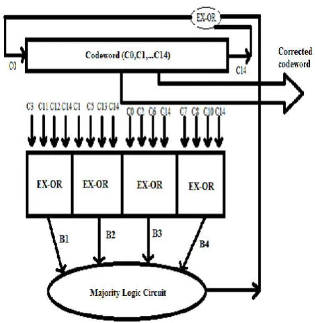
There are many methods for error detection and correction. TMR i.e. Triple Modular Redundancy and ECC i.e. Error Correction Codes are some of the error detection methods. Majority Logic Decoding is another technique that is used for error correction. ML Decoding method has many advantages. ML Decoding is simple and it
Logic Decoder is shown in Fig. 1. For this, EG
are used. (15,7,5) Euclidean Geometry Low Density Parity Check codes are used for error correction. This corrector has four ex-or gates, with codewords as input.
from the ex-or gates are sent to the ML circuit. Finally, the output of ML circuit is ex-ored with C14 bit to get new C0 value. Hence, this process continues for ‘N’ number of cycles. ‘N’ is the length of the codeword.
depends on the length of the message bits. Here, there are seven message bits and fifteen codewords. The flowchart for this method is explained in Fig. 2. In the ML circuit, the number of ‘0’ and number of ‘1’ are counted. If number of 1 is greater than number of 0, then the corresponding bit is changed using ex-or gate. Otherwise, the corresponding bit is not changed. If errors are present in the codeword, then corrected codeword is obtained after ‘N’ cycles using above method.
International Journal of Current Research
Vol. 9, Issue, 07, pp.54604-54608, July, 2017
Jinendra. D. Bhandekar and Navalgund, S. S. 2017. “An efficient error detection and correction technique for memories using mldd 54604-54608.
Available online at http://www.journalcra.com
AN EFFICIENT ERROR DETECTION AND CORRECTION TECHNIQUE FOR MEMORIES
neering and Technology, Dharwad
neering and Technology, Dharwad
Memory is an important component of an embedded system. Memory testing is very complex. Large error rates are occurring because of technology scaling and also due to higher integration densities. ct to the memories. This paper focuses on the design of an efficient system, that detects and corrects the error. Hence, the number of cycles LDPC codes, that is, Euclidean Geometry Low ty Check codes are used here. Previous method like Majority Logic Decoding requires more number of cycles for detection and correction of error. But, this paper deals about Majority Logic Detector/Decoder (MLDD) technique wherein error detection and correction takes place in less number of cycles. Hence, the speed of operation can be increased, power consumption can be reduced
ribution License, which permits unrestricted
There are many methods for error detection and correction. i.e. Triple Modular Redundancy and ECC i.e. Error Correction Codes are some of the error detection methods. Majority Logic Decoding is another technique that is used for error correction. ML Decoding method has many advantages. ML Decoding is simple and it has less complexity. Majority Logic Decoder is shown in Fig. 1. For this, EG-LDPC codes are used. (15,7,5) Euclidean Geometry Low Density Parity Check codes are used for error correction. This corrector has or gates, with codewords as input. Later, the outputs or gates are sent to the ML circuit. Finally, the ored with C14 bit to get new C0 value. Hence, this process continues for ‘N’ number of cycles. ‘N’ is the length of the codeword. The length of the codeword depends on the length of the message bits. Here, there are seven message bits and fifteen codewords. The flowchart for this method is explained in Fig. 2. In the ML circuit, the number of ‘0’ and number of ‘1’ are counted. If number of 1 is n number of 0, then the corresponding bit is changed or gate. Otherwise, the corresponding bit is not changed. If errors are present in the codeword, then corrected codeword is obtained after ‘N’ cycles using above method.
INTERNATIONAL JOURNAL OF CURRENT RESEARCH
Fig. 1. ML Decoder for error correction (Dandem Sudhakar and Indrani, 2015)
Fig. 2. Flowchart (Dandem Sudhakar and Indrani, 2015)
But, if no errors are present in the codeword, then also ‘N’ iterations are required to determine that no error is present in the codeword. This is the major disadvantage of this method. Therefore, an efficient error detection and correction method will be explained in this paper.
MATERIALS AND METHODS
This section deals about the efficient error detection and correction methodology. The efficient ML Detector/Decoder is used for detecting and correcting the error. EG-LDPC codes are used for this method. In this section, the encoding method, the efficient decoding method and the control logic are explained. For the encoding and decoding methods, (15,7,5)
EG-LDPC codes are used. Using this method, the errors present in the codeword can be detected in three cycles only. If there are no errors in the codeword, then also it requires three cycles for detection. But, the number of cycles for error correction depends on the length of the codeword.
Fig. 3. Memory and the efficient MLDD
The memory system is shown in Fig. 3. The message bits are initially encoded. Later they are stored in the memory. The information bits that are stored in the memory can get changed because of various reasons like changes in the operating voltage, integration densities, etc. To detect and correct these errors in the codeword, efficient MLDD is used. It can detect the errors in only three cycles.
Encoder Circuit
[image:2.595.52.275.332.616.2]The generator matrix is shown in Fig. 4. It is an important matrix because the encoder circuit depends on the generator matrix. (15,7,5) Euclidean Geometry Low Density Parity Check codes are used for the encoding method. Generator matrix consists of unit matrix and parity matrix.
Fig. 4. Generator matrix [9]
Fig. 5. Encoder circuit
[image:2.595.308.556.398.698.2]Flowchart of efficient MLDD
The flowchart of efficient MLDD is shown in Fig. 6. Initially the codewords are given as input. Later, the corresponding bits of the codeword is ex-ored. Then, the output of the ex-or gates are sent to the control logic as well as the majority logic circuit. Control logic detects the errors in the codeword. If there are no errors in the codeword, the decoding process is stopped after three cycles. But, if there are errors in the codeword, then the correction of the codeword takes place. Fifteen cycles are required for error correction.
As shown in Fig. 6, the output of the 2nd OR gate is important. Because if the output is 1, it means there is error in the codeword. If the output is 0, it means there is no error in the codeword. The error if present in the codeword has to be corrected. In the ML circuit, if number of 1 is greater than number of 0, then the bit is corrected. Then the codeword can be shifted. Therefore, as shown in the flowchart, the error correction requires ‘N’ cycles. Error detection and correction can be made for any length of codeword using this efficient MLDD method. Hence, this method can be used for any type of memory.
[image:3.595.314.556.51.356.2]
Fig. 6. Flowchart
Decoder Circuit
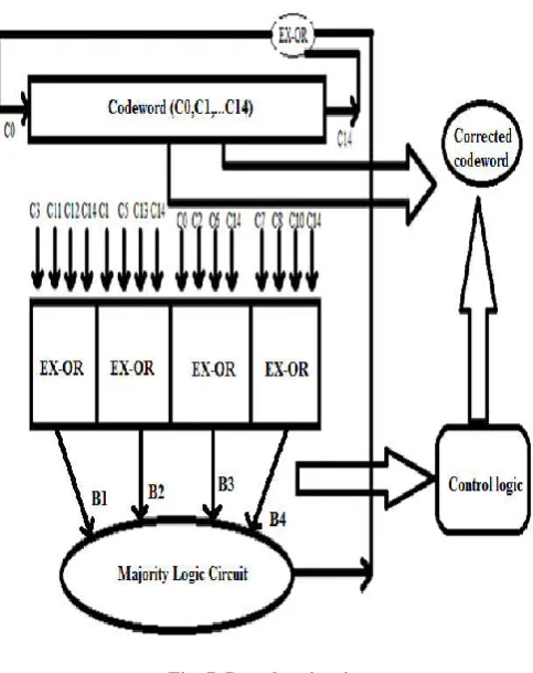
Efficient ML Detector/Decoder is used for error detection and correction. Fig. 7 depicts the efficient ML Detector/Decoder. The output of encoder circuit, that is 15-bit codewords are given as input to this efficient ML Detector/Decoder. Later, those codewords are sent to the ex-or gates as shown in Fig. 7. Here, 4-input ex-or gates are used. The output from the ex-or gates are sent to both ML circuit and control logic. Control logic is shown in Fig. 8. Control logic detects error in 3 cycles. If errors are present in the codeword, after 15 cycles the corrected codeword is obtained. B1, B2, B3, B4 are the outputs from the ex-or gates. C14th bit of the codeword is ex-ored with output of the ML circuit. The output of ML circuit depends on the values of B1, B2, B3 and B4. If B1, B2, B3 and B4 are 0, then output of ML circuit is 0. If any value of B1 to B4 is 1, then the output of ML circuit is 1.
Fig. 7. Decoder circuit
[image:3.595.49.275.333.571.2]C14 bit and ML circuit output are ex-ored to get new value of C0. The new C0 value is placed in its position, after shifting the previous codeword. Fig. 8 depicts the control logic. Control logic is required for error detection. The output from the 4-input ex-or gates are sent to the control logic. In the 1st cycle, the output from 1st OR gate is stored in the first register. In the 2nd cycle, the output from 1st OR gate is stored in the first register by shifting its previous value to the second register. In the 3rd cycle, the output from 1st OR gate is directly sent as input to the 2nd OR gate. The other two inputs to the 2nd OR gate are the values stored in the registers. If the output of 2nd OR gate is 0, it means there is no error in the codeword. But, if the output of the 2nd OR gate is 1, it means there is error in the codeword. The error present in the codeword has to be corrected.
[image:3.595.329.539.560.764.2]In the control logic, the 1st OR gate is having four inputs and the 2nd OR gate is having three inputs. Each register stores single bit value.
RESULTS AND ANALYSIS
This section deals about the results and analysis. The software used to design the efficient error detector and corrector is Xilinx ISE 14.3. The code is written in Verilog HDL. The length of the message bits is 7 and length of the codeword is 15.
Output of the encoder
[image:4.595.310.556.176.462.2]Encoder circuit is an important circuit because, the message bits are encoded. Here, message bits of length 7-bits are used for encoding. The output of the encoder circuit is of length 15-bits. The RTL schematic for encoder circuit is shown in Fig. 9. Here, d0 to d6 are the seven inputs. C0 to C14 are the fifteen outputs. The simulation results for the encoder is shown in Fig. 10. For the various inputs, the outputs are obtained. Here, d0 to d6 are the message bits and they are of 7-bits. These message bits are encoded to get the codewords. The codewords has two parts. That is, it consists of information bits and parity bits. Here, there are 7 information bits and 8 parity bits in the codeword. The information bits of the codeword is same as the message bits. But, the corresponding information bits are ex-ored to get the parity bits. In the simulation result, the corresponding codeword is obtained for the input message bits.
[image:4.595.64.265.403.551.2]Fig. 9. RTL schematic of the encoder
Fig. 10. Simulation results of the encoder
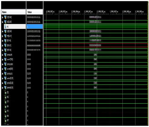
Output of the decoder
Decoder detects and corrects the error present in the codeword. The RTL schematic of the efficient MLDD is shown in the Fig. 11. The codeword is given as the input to the efficient MLDD. This efficient MLDD has the control logic, that detects the error only in 3 cycles. If errors are present in the codeword, then 15 cycles are required to correct the codeword. The simulation results of the efficient MLDD is shown in the Fig. 12. Here, the codeword obtained from the encoder is given as
the input to the efficient MLDD. Hence, there is no error in the codeword. The efficient MLDD has many advantages compared to previous method like ML Decoding. The decoding time of the efficient MLDD is very less. Also, it occupies lesser area. The speed of operation of the efficient MLDD is high. Therefore, efficient MLDD can be used for all types of memories and nano-memories.
Table 1. Comparison between efficient majority logic detector/decoder and ml decoding techniques
Technique Total no. of cycles
Detection of error Correction of error
Efficient Majority Logic
Detector/Decoder 3 N
[image:4.595.310.557.499.708.2]ML Decoding N N
Fig. 11. RTL schematic of the decoder
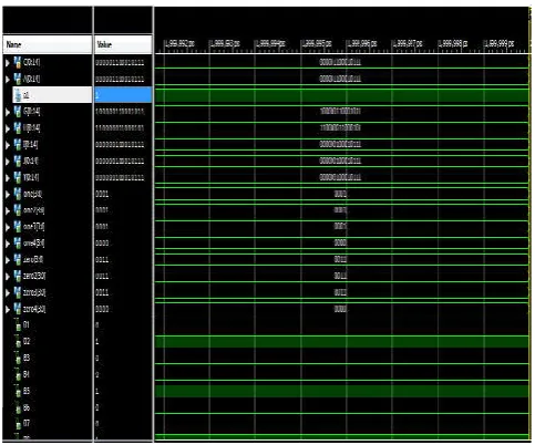
Fig. 12. Simulation results of the decoder
[image:4.595.53.273.587.652.2]Fig. 13. Simulation results of the decoder
Conclusion
The design of an efficient Majority Logic Detector/Decoder is explained in this paper. This system can detect and correct the errors present in the codeword in less decoding time. This system can be used for memory applications. (15, 7, 5) EG-LDPC codes are used and detection of errors requires only 3 cycles for any length of the codeword. The control logic is an important component of the efficient MLDD. The efficient MLDD has high speed of operation compared to ML Decoding method. The number of components in the efficient MLDD are less and the overall area required for this system is very less. There are many disadvantages of the ML Decoding method. Therefore, efficient Majority Logic Detector/Decoder can be used.
Acknowledgement
I would like to thank the Management of SDM Education Society for the support and encouragement. I would like to express my gratitude to the Principal and the Dean of SDM College of Engineering and Technology, Dharwad for their encouragement of this work. I would like to thank the HOD and the PG Co-ordinator of E&C Department for their concern about my work and constructive suggestions. I take this opportunity to express my deep sense of gratitude to my guide Prof. S. S. Navalgund, Department of ECE, SDM College of Engineering and Technology, Dharwad for his keen interest and valuable help throughout this work. I would like to extend my thanks to the teaching faculty, non-teaching staff and my friends for their support and encouragement.
REFERENCES
Baumann, R.C. “Radiation-induced soft errors in advanced semiconductor technologies”, IEEE Trans. Device Mater.
Reliabil., vol. 5, no.3, pp. 301–316, Sep. 2005.
Dandem Sudhakar, K.S.Indrani, “Novel Error-Detection and Correction Technique for Memory Application”, International Journal of Emerging Engineering Research
and Technology, Volume 3, Issue 11, November 2015.
Gallager, R. “Low-density parity-check codes”, IRE Trans.
Information Theory, pp.21-28, Jan.1962.
Iqra Ahmed, Fatima Ejaz, Safa Abdul Karim, Sehrish Khan, Meemona Khanam, “A Review On Numerical Error Correction Using Various Techniques”, International
Journal of Scientific & Technology Research, Volume 4,
Issue 07, July 2015.
Jayarani M.A, Dr.M.Jagadeeswari, “A novel fault detection and correction technique for memory applications”, IEEE, 2013.
Liu, S., P. Reviriego, and J. Maestro, “Efficient majority logic fault detection with difference-set codes for memory applications”, IEEE Trans. Very Large Scale Integr. (VLSI) Syst., vol. 20, no. 1, pp. 148–156, Jan. 2012.
Mohd Jaffar Ahmed Khan, Mohd Shahbaz Khan, E.Ramana, “A Novel Approach Efficient Majority Logic Fault Detection Techniques for Memory Applications”, International Journal of Scientific Engineering and
Technology Research, Vol.03, Issue.49 December-2014.
Naidu Babu, N. V. P., P. M. Francis, B. Prasad Kumar, “Efficient Fault Detection Majority Logic Correction with in Memory with Difference-Set Codes”, International
Journal of Scientific Engineering and Research (IJSER),
Volume 1, Issue 1, September 2013.
Pedro Reviriego, Juan A. Maestro, and Mark F. Flanagan, “Error Detection in Majority Logic Decoding of Euclidean Geometry Low Density Parity Check (EG-LDPC) Codes”,
IEEE Trans. Very Large Scale Integration (VLSI) Systems,
Vol.21, No.1, January 2013.
Shabana, SK. K.Hanumantha Rao, “Novel Correction and Detection for Memory Applications”, International Journal
of Research (IJR), Vol-1, Issue-11, December 2014.
Vasic, B. and S.K.Chilappagari, “Information theoretical frame work for analysis and design of nano scale fault-tolerant memories based on low-density parity-check codes”, IEEE
Trans. Circuits Syst.I, Reg. Papers, vol.54, no.11,
Nov.2007.