VARIABLE SPEED CONSTANT FREQUENCY SCHEME FOR WIND POWER GENERATION
1
Subrahmanya Hebbar,
2Manu, J.
Global Academy of
ARTICLE INFO ABSTRACT
This paper deals with the technical details involved in the generation of power through wind technology. It discusses the factors responsible for generation of wind power and the limitations of the generator. While the emphasis is given on the ‘Variable sp
production of electricity using wind power, the paper also gives insight into ac energy storage methods.
Copyright©2017, Subrahmanya Hebbar et al. This is an open access article distributed under the Creative Commons Att unrestricted use, distribution, and reproduction in any medium, provided the original work is properly cited.
1.
INTRODUCTION
Renewable Energy Sources are those energy sources which are not destroyed when their energy is harnessed. Human use of renewable energy requires technologies that harness natural phenomena, such as sunlight, wind, waves, water flow, and biological processes such as anaerobic digestion, biological hydrogen production and geothermal heat. Amongst the above mentioned sources of energy there has been a lot of development in the technology for harnessing energy from the wind. Wind is the motion of air masses produced by the irregular heating of the earth’s surface by sun. These differences consequently create forces that push air masses around for balancing the global temperature or, on a much smaller scale, the temperature between land and sea
mountains.
1.1 Principle of energy conversion
Wind mills or turbines works on the principle of converting kinetic energy of the wind in to mechanical energy.
Power available from wind mill,
P = ½ ρA V³
Where,
ρ – Air density = 1.225 Kg / m³ at sea level. 15% due to temperature and pressure variations
*Corresponding author: Chandralekha, M. Global Academy of Technology, Bangalore, India.
ISSN: 0975-833X
Article History:
Received 26th May, 2017 Received in revised form 15th June, 2017
Accepted 26th July, 2017 Published online 31st August, 2017
Citation: Subrahmanya Hebbar, Manu, J. E., Likith, G., Dinesh, C., Dr. Vidya, H. A. and scheme for wind power generation”, International Journal of Current Research
Available online at http://www.journal
Key words:
VSCFS, Variable speed.
RESEARCH ARTICLE
VARIABLE SPEED CONSTANT FREQUENCY SCHEME FOR WIND POWER GENERATION
E.,
3Likith,
G.,
4Dinesh, C.,
5Dr. Vidya,
H.
A.
Global Academy of Technology, Bangalore, India
ABSTRACT
This paper deals with the technical details involved in the generation of power through wind technology. It discusses the factors responsible for generation of wind power and the limitations of the generator. While the emphasis is given on the ‘Variable speed constant frequency scheme’ used for production of electricity using wind power, the paper also gives insight into ac
energy storage methods.
is an open access article distributed under the Creative Commons Att use, distribution, and reproduction in any medium, provided the original work is properly cited.
Renewable Energy Sources are those energy sources which are not destroyed when their energy is harnessed. Human use of renewable energy requires technologies that harness natural phenomena, such as sunlight, wind, waves, water flow, and biological processes such as anaerobic digestion, biological hydrogen production and geothermal heat. Amongst the above mentioned sources of energy there has been a lot of development in the technology for harnessing energy from the n of air masses produced by the irregular heating of the earth’s surface by sun. These differences consequently create forces that push air masses around for balancing the global temperature or, on a much smaller scale, the temperature between land and sea or between
Wind mills or turbines works on the principle of converting kinetic energy of the wind in to mechanical energy.
(1.1)
Air density = 1.225 Kg / m³ at sea level. (changes by 10-15% due to temperature and pressure variations
A – Area swept by windmill rotor = V – Wind speed m/sec.
Air density, which linearly affects the power output at a given speed, is a function of altitude, temperature and barometric pressure. Variation in temperature and pressure can affect air density up to 10 % in either direction. Warm climate reduces air density. This equation tells us that maximum power available depends on rotor diameter.
1.2 Factors control the output of wind energy converte
The wind speed
Cross-section of the wind
Conversion efficiently of rotor
Generator
Transmission system
2.Schemes for wind power generation
Based on the speed and frequency, generally following schemes are identified,
1. CSCFS (Constant Speed
2. DSCFS (Dual Speed Constant Frequency Scheme)
3. VSCFS (Variable Speed Constant Frequency Scheme)
4. VSCF with DO (Variable Speed Constant Frequency
with Double Output)
5. VSVFS (Variable Speed Variable Frequency Schemes)
International Journal of Current Research
Vol. 9, Issue, 08, pp.56398-56403, August, 2017
E., Likith, G., Dinesh, C., Dr. Vidya, H. A. andChandralekha, M. 2017. International Journal of Current Research, 9, (08), 56398-56403.
Available online at http://www.journalcra.com
z
VARIABLE SPEED CONSTANT FREQUENCY SCHEME FOR WIND POWER GENERATION
and
*,6Chandralekha, M.
This paper deals with the technical details involved in the generation of power through wind technology. It discusses the factors responsible for generation of wind power and the limitations of the eed constant frequency scheme’ used for production of electricity using wind power, the paper also gives insight into ac-dc-ac converters and
is an open access article distributed under the Creative Commons Attribution License, which permits
Area swept by windmill rotor = D² sq-m. (D – Diameter)
Air density, which linearly affects the power output at a given speed, is a function of altitude, temperature and barometric tion in temperature and pressure can affect air density up to 10 % in either direction. Warm climate reduces air density. This equation tells us that maximum power available depends on rotor diameter.
actors control the output of wind energy converter
section of the windswept by rotor Conversion efficiently of rotor
chemes for wind power generation
Based on the speed and frequency, generally following
CSCFS (Constant Speed Constant Frequency Scheme) DSCFS (Dual Speed Constant Frequency Scheme) VSCFS (Variable Speed Constant Frequency Scheme) VSCF with DO (Variable Speed Constant Frequency
VSVFS (Variable Speed Variable Frequency Schemes)
INTERNATIONAL JOURNAL OF CURRENT RESEARCH
2.1 VSCFS (variable speed constant frequency scheme)
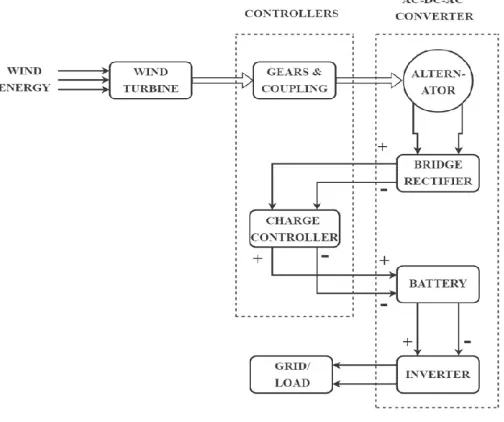
This scheme is used for the variable speed wind turbines. Speed has direct impact on frequency of the output power, so whenever the speed changes frequency also changes. In this scheme output of alternator (synchronous generator) is rectified by bridge rectifier. The DC output is transmitted through DC transmission lines and then converted back to AC using synchronous inverters and fed to grid system. This scheme, involving small wind generators is commonly used in autonomous applications such as street lighting. Due to variable speed operation, it yields higher power for both low and high wind speeds. Both horizontal axis and vertical axis turbines are suitable.
3.Block diagram & description
[image:2.595.40.292.336.547.2]Wind energy from the compressor outlet is fed into the wind turbine. In the windturbine system it converts wind energy into rotational energy that is mechanical energy. Then the rotational energy is converted into electrical energy in alternator. For VSCFS scheme to keep frequency constant AC-DC-AC converter is used.
Fig. 1. Block Diagram
Wind - electric conversion system consists of the following components:-
1. Wind Turbine - Converts wind energy into rotational
(mechanical) energy.
2. Gear system and coupling - It steps up the speed and
transmits it to the alternator rotor.
3. Alternator - Converts rotational energy into AC
electrical power.
4. Rectifier – Converts AC output of the alternator into
DC power.
5. Charge Controller – It constantly inspect the voltage
level of the battery. If the voltage goes past the 14.2V relay activates and prevents the battery from overcharging. Once the voltage reaches the lower cut-off value, relay deactivates and starts charging the battery.
6. Battery – Store the electric power.
4.Wind turbines
A wind turbine is a rotating machine which converts the kinetic energy in wind into mechanical energy. If the mechanical energy is then converted to electricity, the machine is called a wind generator, wind turbine, wind power unit (WPU), wind energy converter (WEC), or aero-generator. Wind turbines can be separated into two types based by the axis in which the turbine rotates. Turbines that rotate around a horizontal axis are more common. Vertical-axis turbines are less frequently used.
4.1 Horizontal axis wind turbines
Horizontal-axis wind turbines (HAWT) have the main rotor shaft and electrical generator at the top of a tower, and must be pointed into the wind. Most have a gearbox, which turns the slow rotation of the blades into a quicker rotation that is more suitable to drive an electrical generator. Since a tower produces turbulence behind it, the turbine is usually pointed upwind of the tower. Turbine blades are made stiff to prevent the blades from being pushed into the tower by high winds. Additionally, the blades are at a considerable distance in front of the tower and are sometimes tilted up a small amount. Downwind machines have been built, despite the problem of turbulence, because they don't need an additional mechanism for keeping them in line with the wind, and because in high winds the 3 blades can be allowed to bend which reduces their swept area and thus their wind resistance. Since cyclic (that is repetitive) turbulence may lead fatigue failures most HAWTs are upwind machines.
4.2 Vertical axis wind turbines
Vertical-axis wind turbines (or VAWTs) have the main rotor shaft arranged vertically. Key advantages of this arrangement are that the turbine does not need to be pointed into the wind to be effective. This is an advantage on sites where the wind direction is highly variable. VAWTs can utilize winds from varying directions. With a vertical axis, the generator and gearbox can be placed near the ground, so the tower doesn't need to support it, and it is more accessible for maintenance. Drawbacks are that some designs produce pulsating torque. Drag may be created when the blade rotates into the wind.
4.3 Controller
The controller starts up the machine at wind speeds of about 8 to 16 miles per hour (mph) and shuts off the machine at about 65 mph. Turbines cannot operate at wind speeds above 65 mph because their generators could overheat.
5.
AC-DC-AC converter systembecause of variable speed, the frequency of generated voltage is not constant. To make the frequency constant, generated voltage is converted into DC, so frequency term disappears and then it is inverted back to AC with 50Hz constant frequency.
5.1 Alternator
An alternator is an electrical generator that converts
mechanical energy to electrical energy in the form of current.
For reasons of cost and simplicity, most alternators use a
rotating magnetic field with a stationary armature.
Occasionally, a linear alternator or a rotating armature with a
stationary magnetic field is used. In principle, any AC
electrical generator can be called an alternator, but usually the
term refers to small rotating machines driven by automotive and other internal combustion engines. An alternator that uses
a permanent magnet for its magnetic field is called a magneto.
Alternators in power stations driven by steam turbines are
called turbo-alternators. Large 50 or 60 Hz three phase
alternators in power plants generate most of the world's electric
power, which is distributed by electric power grids. There are
different kind of generators had been proposed for wind turbines which are widely used in wind farms.
5.2 Rectifier
A rectifier is an electrical device that converts alternating current (AC), which periodically reverses direction, to direct current (DC), which flows in only one direction. The process is known as rectification. Physically, rectifiers take a number of forms, including vacuum tube diodes, mercury-arc valves, copper and selenium oxide rectifiers, semiconductor diodes,
silicon-controlled rectifiers and other silicon-based
semiconductor switches. Historically, even synchronous electromechanical switches and motors have been used. Early radio receivers, called crystal radios, used a "cat's whisker" of fine wire pressing on a crystal of galena (lead sulphide) to serve as a point-contact rectifier or "crystal detector". Rectifiers have many uses, but are often found serving as components of DC power supplies and high-voltage direct current power transmission systems. Rectification may serve in roles other than to generate direct current for use as a source of power. As noted, detectors of radio signals serve as rectifiers. In gas heating systems flame rectification is used to detect presence of a flame. Because of the alternating nature of the input AC sine wave, the process of rectification alone produces a DC current that, though unidirectional, consists of pulses of current.
5.2.1 Bridge rectifier
[image:3.595.325.540.51.227.2]A Bridge rectifier is an Alternating Current (AC) to Direct Current (DC) converter that rectifies mains AC input to DC output. Bridge Rectifiers are widely used in power supplies that provide necessary DC voltage for the electronic components or devices. They can be constructed with four or more diodes or any other controlled solid state switches. Depending on the load current requirements, a proper bridge rectifier is selected. Components ratings and specifications, breakdown voltage, temperature ranges, transient current rating, forward current rating, mounting requirements and other considerations are taken into account while selecting a rectifier power supply for an appropriate electronic circuit’s application.
Fig. 2. Bridge Rectifier
Bridge Rectifier Operation
As we know, a single-phase bridge rectifier consists of four diodes and this configuration is connected across the load. During the Positive half cycle of the input AC waveform diodes D1 and D2 are forward biased and D3 and D4 are reverse biased. When the voltage, more than the threshold level of the diodes D1 and D2, starts conducting the load current starts flowing through the load. During the negative half cycle of the input AC waveform, the diodes D3 and D4 are forward biased, and D1 and D2 are reverse biased. Load current starts flowing through the D3 and D4 diodes. We can observe that in both the cases, the load current direction is same, so unidirectional, which means DC current. Thus, by the usage of a bridge rectifier, the input AC current is converted into a DC current. The output at the load with this bridge wave rectifier is pulsating in nature, but for producing a pure DC requires additional filter like capacitor. The same operation is applicable for different bridge rectifiers.
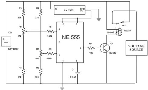
5.3 Battery charge controller
Fig. 3. Battery Charge Controller
A single IC 555, a handful of passive component is all that's needed for making this outstanding, fully automatic lead acid battery charger circuit. The circuit will automatically sense and keep the attached battery up to date. The IC 555 is so versatile; it can be considered the single chip solution for all circuit application needs. The battery which is required to be charged may be kept connected to the circuit permanently, the circuit will continuously monitor the charge level, if the charge level exceeds the upper threshold, the circuit will cut off the
[image:3.595.311.556.512.661.2]charging voltage to it, and in case the charge falls below the lower set threshold, the circuit will connect, and initiate the charging process. Here the IC 555 is configured as a comparator for comparing the battery low and high voltage conditions at pin#2 and pin#6 respectively. As per the internal circuit arrangement, a 555 IC will make its output pin#3 high when the potential at pin#2 goes below 1/3 of supply voltage. The above position sustains even if the voltage at pin#2 tends to drift a little higher. This happens due to the internal set hysteresis level of the IC. However if the voltage continues to drift higher, pin#6 gets hold of the situation and the moment it senses a potential difference higher than 2/3rd of supply voltage, it instantly reverts the output from high to low at pin#3. In this lead acid battery charger circuit design, it simply means that, the pre-sets R2 and R6 should be set such that the relay just deactivates when the battery voltage goes below say 11.3V (for 12V batts) and activates when the battery voltage reaches above 14.2V. Rectifier is connected to Charging circuit through a 15V voltage regulator. Rectifier gets the supply from the wind turbine. These charging circuits prevent the battery from overcharging and backflow of current when there is no supply.
Setting up Higher and Lower threshold Voltage
Initially keep the power supply section at the right hand side of the circuit completely disconnected from the circuit. Connect an external variable voltage source at the (+)/(-) battery points. Adjust the voltage to 10.9V, and adjust the pre-set at pin#2 such that the relay just activates. The above procedure sets the lower threshold operation of the battery. Seal the pre-set with some glue. Now increase the voltage to about 14.4V and adjust the pre-set at pin#6 to just deactivate the relay from its previous state. This will set up the higher cut off threshold of the circuit. The charger is now all set. Remove the external variable source; replace it with any battery which needs to be charged, connect the input of rectifier to circuit. Rest will be automatically taken care of, that is now the battery will start charging and will cut off when it is fully charged, and also will get connected to power automatically in case its voltage falls below the set lower voltage threshold.
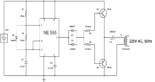
5.4 Inverter
A power inverter, or inverter, is an electronic device or circuitry that changes direct current (DC) to alternating current (AC). The input voltage, output voltage, frequency, and overall power handling depend on the design of the specific device or circuitry. The inverter does not produce any power; the power is provided by the DC source. A power inverter can be entirely electronic or may be a combination of mechanical effects (such as a rotary apparatus) and electronic circuitry. Static inverters do not use moving parts in the conversion process. Inverter circuits can either use thyristors as switching devices or transistors. Normally for low and medium power applications, power transistors are used. The reason for using power transistor is they have very low output impedance, allowing maximum current to flow at the output. One of the important applications of a transistor is in switching. For this application, the transistor is biased in saturation and cut-off region. When the transistor is biased in saturation region, both the collector emitter and collector base junctions are forward biased. Here the collector-emitter voltage is minimum and collector current is maximum. Another important aspect of this circuit is the oscillator. An important use of 555 Timer IC is in its use as an
[image:4.595.310.563.114.249.2]as table multivibrator. An as table multivibrator produces an output signal which switches between the two states and hence can be used as an oscillator. The frequency of oscillation is determined by the values of capacitor and resistors.
Fig. 4. 12 V DC to 220V AC inverter circuit
Circuit Components
V1 = 12V R1 = 100k Ohms R2 = 100k Ohms R3 = 10 Ohms R4 = 10 Ohms Q1 = TIP41 Q2 = TIP42
D1 = D2 = D3 = IN4007 C1 = 0.1μF
C2 = 0.01μF C3 = 2200μF
T1 = 12V/220V step up transformer NE555
5.4.1 Oscillator design using timer 555
An Astable Multivibrator is an oscillator circuit that continuously produces rectangular wave without the aid of external triggering. So Astable Multivibrator is also known as Free Running Multivibrator. Figure 5 shows the circuit diagram of a 555 Timer wired in Astable Mode. 8th pin and 1st pin of the IC are used to give power, Vcc and GND respectively. The 4th pin is RESET pin which is active low and is connected to Vcc to avoid accidental resets. 5th pin is the Control Voltage pin which is not used. So to avoid high frequency noises it is connected to a capacitor C1 whose other end is connected to ground. Usually C1 = 0.01μF. The Trigger (pin 2) and Threshold (pin 6) inputs are connected to the capacitor which determines the output of the timer. Discharge pin (pin 7) is connected to the resistor Rb such that the capacitor can discharge through Rb. Diode D connected in parallel to Rb is only used when an output of duty cycle less than or equal to 50% is required. Since the Control Voltage (pin 5) is not used the comparator reference voltages will be 2/3 Vcc and 1/3 Vcc respectively. So the output of the 555 will set (goes high) when the capacitor voltage goes below 1/3 Vcc and output will reset (goes low) when the capacitor voltage goes above 2/3 Vcc.
Working
will be HIGH and of the higher comparator will be LOW. This SETs the output of the SR Flip-flop. Thus the discharging transistor will be OFF and the capacitor C starts charging from Vcc through resistor Ra &Rb. When the capacitor voltage will become greater than 1/3 Vcc (less than 2/3 Vcc), the output of both comparators will be LOW and the output of SR Flip-flop will be same as the previous condition, thus the capacitor continuous to charge. When the capacitor voltage will becomes slightly greater than 2/3 Vcc the output of the higher comparator will be HIGH and of lower comparator will be LOW. This resets the SR Flip-flop. Thus the discharging transistor turns ON and the capacitor starts discharging through resistor Rb. Soon the capacitor voltage will be less than 2/3 Vcc and output of both comparators will be LOW. So the output of the SR Flip-flop will be the previous state, so the discharging of capacitor continuous. When the capacitor voltage will become less than 1/3 Vcc, the output SETs since the output of lower comparator is HIGH and of higher comparator is LOW and the capacitor starts charging again. This process continuous and a rectangular wave will be obtained at the output.
Design
Capacitor Charges through Ra and Rb.
T_high = 0.693(Ra+Rb)C (6.1)
Capacitor Discharges through Rb
T_low = 0.693RbC (6.2)
Output Frequency,
f = 1/(T_low + T_high)
= 1.44/((Ra + 2Rb) * C) (6.3)
Duty Cycle,
D = T_high/(T_high + T_low)
= (Ra+Rb)/(Ra+2Rb) (6.4)
Where,
T_high and T_low are the time period of HIGH and LOW of the output of 555.
From this we can find that Duty Cycle less than or equal to 50% cannot be obtained. There are two ways to obtain this.
Using a diode parallel to resistor Rb, 50% duty cycle can be
achieved. In this method a diode is connected parallel to resistor Rb. Thus the charging current of capacitor will bypass the resistor Rb, therefore, Thigh = 0.693RaC. Thus a Duty Cycle less than or equal to 50% can easily obtained. To get 50% duty cycle the value of Ra &Rb must equal and a diode should be connected in parallel with the Rb. Using above equation the values of Ra &Rb are calculated and it is Ra=Rb=96k ohm. So 100k Ohm resistors are selected.
5.4.2 Switching circuit
The main aim of the work is to develop an AC signal of 220V. This requires use of high power transistors to allow the flow of maximum amount of current to the load. For this reason a power transistor TIP41 with a maximum collector current of 6A is used, where the base current is given by the collector current divided by the DC current gain. This gives a bias current of about 0.4A *10, i.e.4A. However since this current is more than the maximum base current of the transistor, a value less than the maximum base current is preferred, Let us assume the bias current to be 1A. The bias resistor is then given by
Rb = (Vcc– Vbe(on) )/I bias (6.5)
Fig.5. Astable Multivibrator using 555 Timer Block Diagram
For each transistor, the Vbe(on) is about 2V. Thus Rb for each is
calculated to be 10 Ohms. Since the diodes are used for biasing, the forward voltage drop across the diodes should be equal to the forward voltage drops across the transistors. For this reason, diodes 1N4007 are used. The design considerations for both the PNP and NPN transistors are same and a PNP power transistor TIP42 is used.
5.4.3 Output load design
Since the output from the switching circuit is a pulse width modulated output, it might contain harmonic frequencies other than the fundamental AC frequency. For this reason, an electrolyte capacitor needs to be used to allow only the fundamental frequency to pass through it. Here an electrolyte capacitor of 2200uF is used which is large enough to filter out the harmonics. Since it is required to get 220V output, it is preferred to use a step up transformer. Here a 12V/220V step up transformer is used.
6.
Energy storageWind power turbines have operational limitations over very high and very low speeds. When the power generated exceeds the demand, excess energy can be stored to be used at other times.
Excess energy can be conveniently stored in storage
batteries in the form chemical energy.
Excess energy can also be stored in water power storage
in the form of mechanical energy. Wind power plant (WPP) along with Hydroelectric power plant (HPP), when generated power (Pg) exceeds the power demand (Pd), helps to partly divert hydro power plant output to Pumping motor (PM) to pump water from an auxiliary reservoir at the bottom of the dam to main reservoir.
Excess energy can also be stored in the form of
compressed air. When wind is not blowing, energy stored in compressed air could be used to drive wind turbine whose shaft would then drive a generator, thus supplying the needed power.
7.
Advantages & disadvantages7.1 Advantages
The wind is free and with modern technology it can be
captured efficiently.
Once the wind turbine is built the energy it produces
does not cause greenhouse gases or other pollutants.
Remote areas that are not connected to the electricity
power grid can use wind turbines to produce their own supply.
Wind turbines have a role to play in both the developed
and third world.
Wind turbines are available in a range of sizes which
means a vast range of people and businesses can use them.
6.2 Disadvantages
Installation cost is high.
Often maintenance is required.
Installation site must be non-residential area.
Conclusion
The new mantra of the 21st century is sustainable development, which means that the local population should be able to absorb the development of a country or region. We want the entire population to have access to uninterrupted supply of electricity. This puts a huge burden on the limited fossil fuel resources. The benefits of using wind power over other resources lies in its minimum operational cost. A variable speed constant frequency scheme has been implemented for conversion of wind into electrical energy. So we can generate constant frequency electricity at different speed of wind. Various option of storage facility makes it versatile source of energy. Modern turbines are totally controlled by computers that are totally safe. Since wind is clean source of energy, the power conversion does not pose any environmental hazard.
Future work
In the Inverter part timer 555 is a square wave generator, so the output of switching circuit is square wave, by using proper filter sine wave can be achieved. Or we can replace this oscillator with other sine wave oscillator.
REFERENCES
Basics of Wind Energy Conversion Systems (Wecs),
VenkataYaramasu; Bin WuModel Predictive Control of Wind Energy Conversion Systems; Year: 2017.
Modeling and simulation of AC-DC-AC converter system for MW-level direct-drive wind turbine grid interface, Chuanwei Yang; Hui Liang; Jiuchun Jiang2006 37th IEEE Power Electronics Specialists Conference; Year: 2006.
Renewable energy sources and conversion technology – N.K. Bansal, Electrical India- 15th May 2001 (Wind power special).
VSCF wind turbine control strategy for maximum power generation, Yunqi Xiao; PengxiaoJia, 2010 8th World Congress on Intelligent Control and Automation; Year: 2010.