Master thesis
Multi-level views in a SUM-based
environment
Peter Lanting
Faculty of Electrical Engineering, Mathematics and Computer Science (EEMCS)
Department of Computer Science - Software Engineering specialisation
EXAMINATION COMMITTEE
dr. L. Ferreira Pires dr. ir. M.J. van Sinderen
Contents
List of Figures VI
List of Listings VII
List of Abbreviations IX
Acknowledgements XI
Abstract XIII
1 Introduction 1
1.1 Motivation . . . 1
1.2 Objectives . . . 2
1.3 Research questions . . . 3
1.4 Approach . . . 3
1.5 Structure of the report . . . 4
2 Multi-Level Modelling 7 2.1 MDA limitations . . . 7
2.1.1 Dual Classification . . . 8
2.1.2 Class/object Duality . . . 8
2.1.3 Replication of Concepts . . . 9
2.2 OCA principles . . . 9
2.2.1 Clabject . . . 10
2.2.2 Potency-based deep instantiation . . . 11
2.3 OCA requirements . . . 12
2.4 Visualization of PLM using LML . . . 13
2.5 Conclusion . . . 15
3 View- and SUM-based Modelling 17 3.1 View-based modelling . . . 17
3.1.1 Standard terminology . . . 18
3.1.2 Consistency . . . 19
3.2 SUM-based modelling . . . 20
3.3 Multi-level SUM-based modelling . . . 23
3.3.1 ATL Adapter . . . 24
3.3.2 Multi-level transformations . . . 25
II CONTENTS
3.4 Conclusion . . . 26
4 Available tool support 27 4.1 nAOMi . . . 27
4.1.1 Structure and functionality . . . 27
4.1.2 Current state of development . . . 30
4.2 Melanee . . . 30
4.2.1 Structure and functionality . . . 30
4.2.2 Current state of development . . . 32
4.3 Conclusion . . . 32
5 Context view design 33 5.1 View selection . . . 33
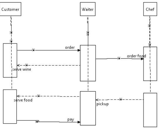
5.1.1 Sequence diagram . . . 34
5.1.2 Context diagram . . . 36
5.1.3 Selection . . . 37
5.2 Context view implementation . . . 38
5.2.1 Metamodel design . . . 38
5.2.2 DSL implementation . . . 39
5.2.3 SUM metamodel extension . . . 41
5.2.4 Alternative representations . . . 42
5.3 Structural view extension . . . 43
5.4 Conclusion . . . 44
6 Model transformations 45 6.1 ATL . . . 45
6.2 Transformation chain . . . 46
6.3 Generate view transformations . . . 47
6.3.1 Generate context view . . . 48
6.3.2 Generate structural view . . . 50
6.3.3 Generate helper view . . . 51
6.3.4 Helpers . . . 51
6.4 Merge transformations . . . 52
6.4.1 Merge context view . . . 53
6.4.2 Merge structural view . . . 54
6.4.3 Merge helper view . . . 54
6.5 Merge SUM transformation . . . 55
6.6 Conclusion . . . 56
7 Implementation 57 7.1 Eclipse plug-ins . . . 57
7.1.1 Transformation plug-in . . . 58
7.1.2 SUM plug-in . . . 59
7.2 Dimension configuration . . . 59
7.3 Conclusion . . . 61
CONTENTS III
8.1.1 Requirements . . . 63
8.1.2 Description . . . 64
8.1.3 Actors . . . 65
8.2 Constructing the context model . . . 66
8.3 Constructing the structural model . . . 67
8.4 Linking the views . . . 69
8.5 Conclusion . . . 70
8.5.1 Current limitations . . . 71
8.5.2 Other cases . . . 71
9 Conclusion 73 9.1 Limitations . . . 74
9.2 Further research . . . 75
References 79
Appendices 81
A Struct SUM2View 83
B Context SUM2View 87
C Struct View2SUM 93
D Context View2SUM 97
E Merge SUM 101
F Helper SUM2View 105
G Helper View2SUM 107
List of Figures
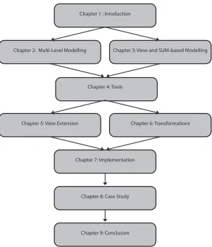
1.1 Report outline and chapter dependencies. . . 5
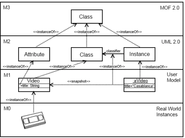
2.1 The four-layer architecture of MDA. . . 8
2.2 The Orthogonal Classification Architecture. . . 10
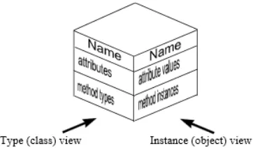
2.3 A clabject with a type and an instance facet [14]. . . 10
2.4 The PLM rendered using LML syntax [28]. . . 14
3.1 Conceptual model of the Architecture Description [32]. . . 18
3.2 Worst case scenario: view-based approach vs. SUM-based approach [19]. . . 20
3.3 Dimension-based navigation principle [19]. . . 22
3.4 Dimension-based navigation in nAOMi. . . 23
3.5 Illustration of a Single-Underlying Model and its views [18]. . . 23
3.6 A multi-level behavioural view, instantiated from a part of the KobrA metamodel [10]. . . . 24
3.7 Architecture of the multi-level ATL adapter. . . 25
3.8 Transformation without explicitly stating * potency defined on component [11]. . . 26
4.1 Kobra-oriented SUM metamodel [10]. . . 28
5.1 SUM metamodel extension concept for a sequence diagram . . . 35
5.3 DSL representation for a sequence diagram . . . 35
5.2 Example of a sequence diagram . . . 36
5.4 Example of context diagram . . . 36
5.5 Context metamodel concept . . . 37
5.6 DSL representation for a context diagram . . . 37
5.7 The context metamodel . . . 39
5.8 Context model based on the metamodel. . . 40
5.9 DSL visualization editor for system entity . . . 41
5.10 DSL representation of the context model. . . 41
5.11 The currently implemented SUM metamodel . . . 42
5.12 The extended SUM metamodel . . . 42
5.13 Helper view, used to connectsubSystemswithcomponents . . . 43
5.14 Context model in specifiction(black box) mode . . . 43
5.15 The current structural view metamodel . . . 44
6.1 Visualization of the transformation chain . . . 46
7.1 Extension point definitions (left) and extensions (right) . . . 58
VI LIST OF FIGURES
8.1 New SUM project with onesystementity. . . 66
8.2 Context view of the holiday booking system. . . 67
8.3 Structural view with one main component. . . 68
8.4 Structural view of the holiday booking system. . . 69
List of Listings
3.1 Multi-level ATL code . . . 26
6.1 Context SUM2View: Actor and RelationshipFrom rule . . . 48
6.2 Struct SUM2View: Component and Creates rule . . . 50
6.3 Contex SUM2View: Helpers . . . 51
6.4 Context SUM2View: Helper createMethods . . . 52
6.5 Context View2SUM: Actor and RelationshipFrom rule . . . 53
6.6 Struct View2SUM: Component and Creates rule . . . 54
6.7 Merge SUM: toTransform helper . . . 55
7.1 Part of the dimensionContainer in the configuration file . . . 59
7.2 Example of a mapping in the configuration file . . . 60
A.1 Struct SUM2View transformation . . . 83
B.1 Context SUM2View transformation . . . 87
C.1 Struct View2SUM transformation . . . 93
D.1 Context View2SUM transformation . . . 97
E.1 Merge SUM transformation . . . 101
F.1 Helper SUM2View transformation . . . 105
G.1 Helper View2SUM transformation . . . 107
H.1 Dimension configuration file . . . 109
List of Abbreviations
ATL ATLAS Transformation Language
CAD Computer-Aided Design
CBD Component-Based Development
DSL Domain Specific Language
EMF Eclipse Modelling Framework
ER Entity Relationship
GMF Graphical Modelling Framework
GPL Graph Product Line
GUI Graphical User Interface
IEC International Electrotechnical Commission
IEEE Institute of Electrical and Electronics Engineers
ISO International Organisation for Standardization
LML Level-agnostic Modelling Language
MDA Model-Driven Architecture
MDE Model-Driven Engineering
MOF Meta Object Facility
OCA Orthogonal Classification Architecture
OMG Object Management Group
X LIST OF ABBREVIATIONS
OSM Orthographic Software Modelling
OWL Web Ontology Language
PIM Platform-Independent Model
PLE Product-Line Engineering
PLM Pan-Level Model
PSM Platform-Specific Model
PVS Prototype Verification System
SUM Single-Underlying Model
SW Semantic Web
SWT Standard Widget Toolkit
UI User Interface
UML Unified Modelling Language
VOSE Viewpoint-Oriented Software Engineering
XML Extensible Markup Language
Acknowledgements
During the time span of my master thesis I have received a lot of support from many people that I would like to thank here. First of all I would like to thank my supervisor Lu´ıs Ferreira Pires, who inspired me to conduct my research in the field of multi-level and SUM-based modelling, and always supported me during my research and writing. I would like to extend my gratitude to my second supervisor Marten van Sinderen, for the support and comments on my work and thesis. Furthermore, I would like to show my gratitude to Christian Tunjic and Ralph Gerbig from the University of Mannheim, for all the support regarding the tools Melanee and nAOMi, which I used during my thesis. Whenever I had problems or questions they found some time to help me, which I greatly appreciated.
Besides, I would like to thank my family, for all the emotional and financial support throughout my study and my life, without them I would be nowhere. Special thanks go to my girlfriend Lily, for all the love and support she gave me throughout the process. Last but not least I would like to thank my friends for all the good times we have had together.
Abstract
In this thesis we investigate the applicability of combining multi-level modelling and Single-Underlying Model (SUM)-based modelling. Multi-level modelling is a modelling methodology that solves the limita-tions of the traditional Model-Driven Architecture (MDA). Multi-level modelling acknowledges the differ-ence between ontological and linguistic entities, and supports an unlimited amount of ontological levels, whereas MDA does not make this distinction and only supports a four-level architecture. SUM-based mod-elling is a branch of view-based modmod-elling that uses one main model to store all the information about a system. From this SUM, different views can be generated on demand. Each view shows a specific part of the system, which can be edited and merged with the SUM, to save the changes.
During this process we also looked into the available tools and found Melanee, a tool that supports the design and transformation of multi-level models, and nAOMi, a tool that supports SUM-based modelling and uses Melanee for the view visualization. nAOMi is still in an early stage of development, and only supported a partial structural view. This inspired us to design an extension for nAOMi that implements an additional view, using both multi-level modelling and SUM-based modelling methodologies. This process consists of several steps such as the selection and design of the view (meta)model, the transformations to generate and merge the view, and the implementation of a modular extension to nAOMi. We chose to implement a context view, because it adds new possibilities to SUM-based modelling in nAOMi, has a clear connection with the currently partly supported structural view, and can be rendered in a custom DSL visualization using the DSL editor of Melanee. Furthermore, we extended the partially supported structural view to a completely supported structural view. For both these views we developed ATL transformations that allow the generation from the SUM, as well as merging the edited views with the SUM. nAOMi is built as an Eclipse plug-in and provides several extension points, which allows us to extend the tool with new views and SUM models. This guarantees that the original code is not changed and thus meets our requirement to provide a modular extension.
In order to test our extension we designed and conducted a case study that resembles the design of a real software system. The results show that there are still some limitations, in both nAOMi and our extension, that mainly concern the visual aspects and rendering of the views. However, all the implemented functionality works, and our extension provides a useful addition to nAOMi.
Chapter 1
Introduction
1.1
Motivation
State-of-the-art methodologies for software design require the use of modelling techniques. The most pop-ular modelling techniques are based on the Model-Driven Architecture (MDA), introduced by the Object Management Group (OMG) in 2001 [35]. Modelling techniques include two different techniques, namely the actual (meta)modelling design of software systems, and the support for model transformations. These transformations enable platform-independent models to be transformed to platform-specific models, or vice versa. Although MDA is the standard for modelling, it still has some limitations and inconsistencies, es-pecially with the metamodelling layering on which it is based. For example, it lacks the ability to carry data across multiple levels. In order to solve these limitations new (meta)modelling techniques were pro-posed [15]. These modelling techniques, now known as multi-level modelling, led to the development of a new architecture, the Orthogonal Classification Architecture (OCA) [12]. In order to enable the utilization of multi-level modelling, the tool Melanee [33] was developed. This tool supports the design of multi-level models, as well as the transformation of these models to other multi-level, or MDA-based, models [9].
Another modelling approach presented in the literature is Single Underlying Model (SUM)-based mod-elling [18], which is a branch of view-based modmod-elling. View-based modmod-elling enables the design of rather complex systems by representing the system in several sub-models, called views. Each view describes a specific aspect of the system, such that the overall complexity can be controlled [20]. SUM-based mod-elling is based on this approach, but instead of using multiple separate views to describe the system, one main model, the SUM, is used to generate these views. By using this technique all the information about the system is stored in the SUM, and the different views can be generated on-demand by the users. These views can then be modified, after which they need to be synchronized with the SUM in order to keep all views consistent. A tool that supports the development of SUM-based modelling is nAOMi [34].
Atkinson et al. proposed the idea of combining multi-level modelling with SUM-based modelling [10]. By developing a new version of nAOMi that supports multi-level modelling, a foundation for developing multi-level SUM-based models was established. In order to represent the multi-level views, nAOMi uses the tool Melanee. Melanee supports the visualization of multi-level models, and also enables the utilization of custom representations. However, the new version of nAOMi is still in an early development stage, and
2 CHAPTER 1. INTRODUCTION
only the structural view of systems is currently supported. In order to contribute to the development of this new field of modelling the tooling needs to be extended with more functionality and views. This project is inspired by this new modelling approach, and the rudimentary tooling that is available. Therefore, during this thesis project, we implement a view as an addition to nAOMi.
1.2
Objectives
The goal of this thesis project is to demonstrate the feasibility of multi-level SUM-based modelling, by extending the existing SUM-based modelling tool nAOMi. Hereby we have also identified the practical limitations that this modelling approach bears in its current state. nAOMi is a SUM-based tool that initially only worked with UML models, but now has a version that also supports multi-level modelling. The tool currently only supports a part of a structural view, and is under development for the complete structural view and a behavioural view. In this project we identified which view would bring a useful addition to the tool, and added this view accordingly. The view is represented in a multi-level environment which is supported by the multi-level model development tool Melanee. This tool has been used to create and represent multi-level views. Using a graphical DSL editor, the view representation can be adjusted such that the view looks like its original design. Since nAOMi is a SUM-based modelling tool, the view should be able to be generated from the SUM, and should be able to merge with the SUM. This required the development of multi-level transformations between the SUM and each view.
Design requirements
The design requirements are the specifications to which the extension should conform. These requirements below show the boundaries of the additional functionality that we have added to nAOMi:
• Design a new view that:
- has unique capabilities that are not covered by the currently implemented views.
- has a logical connection to the current SUM metamodel.
- has a DSL representation that closely resembles the standard visualization of this view.
• Extend nAOMi without affecting the currently available code.
- Add functionality to show a complete overview of the system in the selected view.
1.3. RESEARCH QUESTIONS 3
1.3
Research questions
From the objectives, the following research questions can be defined:
• RQ1: What is the applicability of multi-level SUM-based modelling?
SQ1.1: What is the coverage of multi-level modelling w.r.t. our design requirements?
SQ1.2: What is the coverage of SUM-based modelling w.r.t. our design requirements?
SQ1.3: How stable and complete are the available tools?
• RQ2: How can we extend nAOMi with a view in a modular way?
SQ2.1: How do we extend the SUM metamodel without effecting the original metamodel?
SQ2.2: How do we represent the view in a DSL visualization?
Two main research questions have been defined, the first being a knowledge question and the second being
a design question. The first research question (RQ1) concerns the feasibility of multi-level SUM-based
modelling in its current state and support. Hereby, we look into the maturity and current state of the
multi-level modelling methodology(SQ1.1)) the maturity of SUM-based modelling methodology(SQ1.2)and the
maturity of the tools that are currently supporting multi-level modelling as well as SUM-based modelling (SQ1.3). The second research question (RQ2)asks for an implementation of a modular extension to the tool nAOMi. In order to create a modular extension we need to find a way to extend the current SUM
metamodel without overwriting the original one(SQ2.1). Furthermore, we should find a manner to represent
the extended view in its standard DSL visualization(SQ2.2).
1.4
Approach
The approach we have taken in this project consists of the following steps:
1. Study existing views and choose one to extend the tool with.
2. Explore the tools nAOMi and Melanee.
- Study the source code of both tools.
- Study the core structure of the KobrA-based SUM in nAOMi.
- Identify the interoperability between nAOMi and Melanee.
4 CHAPTER 1. INTRODUCTION
4. Create the graphical representation for the view using the DSL editor in Melanee, and identify how to implement this representation using code.
5. Create the multi-level transformations between the Kobra-based SUM and the view.
6. Implement the view as an extension to nAOMi.
- Figure out how to generate the view from the SUM.
- Figure out how to merge the view with the SUM.
7. Design a case study that shows the applicability of the extended view.
- Test the implementation with this case study.
1.5
Structure of the report
1.5. STRUCTURE OF THE REPORT 5
Chapter 1 : Inroduction
Chapter 2: Multi-Level Modelling Chapter 3: View-and SUM-based Modelling
Chapter 4: Tools
Chapter 5: View Extension Chapter 6: Transformations
Chapter 7: Implementation
Chapter 8: Case Study
[image:21.612.146.447.206.558.2]Chapter 9: Conclusion
Chapter 2
Multi-Level Modelling
Multi-level modelling is an approach to modelling whereby multiple ontological classification levels are covered within one model. This approach is used to solve some limitations of the classical Model-Driven Architecture (MDA) [35]. In this chapter these limitations and their solutions regarding multi-level mod-elling are discussed. Furthermore this chapter elaborates on the Pan Level Model and the Level-agnostic Modelling Language, which implement the Orthogonal Classification Architecture.
2.1
MDA limitations
The Object Management Group (OMG) fostered the development of the Model-Driven Architecture (MDA), in order to create an architecture that achieves interoperability, portability and reusability of platform-independent models. MDA is based on two main techniques, namely, metamodelling and model trans-formation. The former can be used to design models of software systems, and the latter can be used to transform these models to, e.g., platform-specific models, or vice versa. MDA is built on the principles of object-oriented modelling, and uses a four-layer metamodelling architecture. The top level M3 is the Meta-Object Facility (MOF) level, which is the metamodelling language to define metamodels at the M2 level. A widely used metamodel language is the Unified Modelling Language (UML) [26], which on its turn can be used to build user models on M1. M0 represents the real world instances of the model, as it can be seen in Figure 2.1.
An important principle that is used within the MDA is strict modelling. Strict modelling implies that every element of a model on level N must be an instance of exactly one element on level N+1. All relationships other than instance-of relationships between two elements must be defined on the same level. Using strict modelling results in many benefits, since it makes it much easier to type-check and therefore debug pro-grams or models. This contributes to a rather simple design of models. Loose modelling is the opposite of strict modelling, and allows all relationships to cross multiple levels and to connect to multiple elements. This usually results in rather complex models that are hard to understand. Besides this, loose modelling increases the chance of defining logical inconsistencies. So although strict modelling gives us some limi-tations towards the relationships between elements, it also gives great benefits for the consistency and the relative simplicity of the models.
8 CHAPTER 2. MULTI-LEVEL MODELLING
[image:24.612.154.467.144.378.2]Strict modelling is one of the underlying reasons for the current limitations in MDA. These limitations of MDA have been identified, and solutions have been proposed in [8] [15] [5]. Almost all of these limitations can be found on the M3 level, where the MOF is defined. The most important limitations are discussed below.
Figure 2.1: The four-layer architecture of MDA.
2.1.1 Dual Classification
One of the main problems with MDA is dual classification. On level M1 in Figure 2.1, there is an element
namedaVideowith an attributetitlethat holds the valueCasablanca. Next to this element there is another
element namedVideowith an attributetitleof type String. Normally speaking,aVideowould be an instance
of Video. However, Figure 2.1 only shows that aVideo is an instance of the linguistic Instance on the
M2 level. This is because MDA only uses linguistic instantiations. So even though aVideo is actually
an instance of two elements, namely the ontological Videoand the linguisticInstance, only the linguistic
instance relation is supported. In order to model the ontological instantiation in MDA, workarounds have to
be used. In Figure 2.1 a stereotyped dependency namedsnapshotis used to represent the instance relation
betweenVideoandaVideo.
2.1.2 Class/object Duality
Another problem with MDA is the Class/Object duality problem. In the MOF there are two kinds of elements
namely, types and instances. Looking at Figure 2.1,Videoinstantiates fromClassandaVideofromInstance.
This means thatVideois the type andaVideois the instance. This makes perfect sense, however, when we
introduce an element that represents the type of a type, this could cause some problems. Imagine that
2.2. OCA PRINCIPLES 9
instantiated (likeaVideois ontologically instantiated fromVideo). Looking from the point of view ofMedia,
Videoshould now be an instance rather than a type. This introduces a problem, sinceVideoshould have the
properties of a type and an instance at the same time, which is not possible according to the MOF. Similar to the previous problem, workarounds have been provided in order to cope with this problem, such as stereotypes and powertypes [25].
2.1.3 Replication of Concepts
Replication of concepts arises when information should be transferred across more than one instantiation level. In UML it is only possible to influence elements on the next instantiation level, e.g., from M3 to M2. So in order to influence over more than one level it is necessary to duplicate this information over multiple levels. This leads to unnecessarily complex models, with the same data replicated by different elements.
Imagine, for example, that there are some properties of theClass type on the M3 level of Figure 2.1 that
should influence the properties of Videoat the M1 level. Since information can only influence the direct
adjacent level, this is not possible without specifying the same information again on level M2.
2.2
OCA principles
For most of the MDA limitations, workarounds have already been provided, but even though they do their job, they bring unnecessary complexity to the models. This leads to more time being used to develop the models, and to additional techniques that have to be learned by the developers in order to create models. Therefore, an architecture that solves these limitations has been developed, namely the Orthogonal Clas-sification Architecture (OCA), which supports multi-level modelling. The theoretical foundations of OCA have been proposed by Atkinson and K¨uhne [12]. Several other researchers contributed to these proposals by creating NIVEL, which is a formal foundation introduced by Asikainen and M¨annist¨o [4], or by using real cases in practice, like Aschauer et al. [3]. Like MDA, OCA uses the principles of strict modelling as a foundation for creating models. As we discussed above, strict modelling gives great benefits regarding consistency and the ease of understanding and developing models. Figure 2.2 shows the same model as Figure 2.1, but now according to OCA.
The main difference that immediately stands out in Figure 2.2 is that this architecture does not use one dimension with four M levels like MDA, but it uses two dimensions each according to the principles of strict modelling. These dimensions are represented by L, for the linguistic dimension, and O, for the ontological dimension. The linguistic dimension consists of three different levels: the top level L0 contains the language definition, which is the Pan-Level Model (PLM); level L1 corresponds to the M1 level of the MDA and contains the models created by the user using instantiations from L0; and the final level L2 represents the real world instances of the elements created at L1. The number of ontological levels is not fixed, and theoretically it can range from only one to an unlimited amount of levels. All the ontological levels are present at the L1 level of the linguistic dimension. Within the ontological dimension, the O0 level represents the main elements from which other elements at the O1 level can be instantiated. O1 contains types that can be instantiated at O2, and so forth, until the lowest ontological level is reached.
instan-10 CHAPTER 2. MULTI-LEVEL MODELLING
tiated from both an ontological type and from a linguistic type. This structure immediately solves the dual classification problem described in Section 2.1.1. Without any workarounds, and using a simple and clear
relationship,aVideocan now be instantiated from bothVideoas well asInstance. Unlike UML, OCA
com-bines types and instances into one element calledClabject, which is discussed in the next section. Therefore,
[image:26.612.215.396.551.657.2]in Figure 2.2Videois instantiated fromClabject, which is both a class and and instance.
Figure 2.2: The Orthogonal Classification Architecture.
2.2.1 Clabject
A key element to enable the utilization of multiple ontological levels is the clabject. The term clabject is originated from the combination of class and object, due to the roles that it combines. In MDA there was a distinction between a type and an instance element, where in OCA the clabject combines both of these elements. In order words, clabjects have both a type facet as well as an instance facet. A visualization of a clabject is shown in Figure 2.3, with on the right hand side the instance facet, and on the left hand side the type facet. Clabjects can also contain attributes and method types, and attribute values and method instantiations, depending on the facet(s) it offers.
Figure 2.3: A clabject with a type and an instance facet [14].
As we showed in the example of the class/object duality problem in Section 2.1.2, in MDA it was impossible
2.2. OCA PRINCIPLES 11
type facet foraVideoon the right, and an instance facet forMediaon the left. This solves the class/object
duality problem and enables the utilization of multiple ontological levels.
2.2.2 Potency-based deep instantiation
In order to solve thereplication of conceptsproblem, it was necessary to find a way to pass on
informa-tion across multiple levels. Therefore Atkinson and K¨uhne introduced the concept of potency-based deep instantiation [8]. Deep instantiation means that elements can be instantiated over more than one level, and the potency helps keep track of the number of instantiations. Every clabject can have a potency, which is a positive integer value representing the number of instantiations it allows. The value of the potency can be classified in three categories:
• Potency 0. With a potency of zero the clabject or attribute cannot be instantiated. This also implies that if a clabject has a potency zero, it corresponds to an abstract class, since it cannot be instantiated.
• Potency 1 or more.Potency with a value of 1 or higher indicates that the clabject or attribute can be instantiated. Depending on the value n of the potency it can be instantiated n times. If, for example,
clabjectxinstantiates clabjecty, ymust have a potency of exactly one lower than the potency of x.
For example, if the potency ofxis one, the potency ofyis zero.
• Potency *.The potency with value * indicates that the number of instantiations allowed by the clabject is unbounded. This means that it is not specified how many instantiations are allowed for the specific clabject. A clabject instantiated from a clabject with potency * can have either again potency * or any positive integer value. Clabjects instantiated from a clabject with a numeric potency value can never get a * potency.
Besides clabjects, the attributes and values of the attributes also have potencies. To prevent any confusion
we use the word potencyfor clabjects, durability for attributes and mutability for the value of attributes.
All these potency values obey the standard rules mentioned above, however, there are a few differences between them. Durability indicates the number of instances of the clabject it belongs to that also have this
attribute. For example, clabject A has a potency of two and an attributexwith durability one. Clabject B
is an instance of clabject A and clabject C is an instance of clabject B. Sincex has a durability of one, it
means that clabject B has an attributexwith durability zero, which then means that clabject C does not have
attributex. Furthermore the durability of zero indicates that the attribute should have a value at this level.
The durability is not allowed to be higher than the potency of its corresponding clabject. This is a logical conclusion from the boundedness of a clabject, and thus cannot exist without one.
Mutability
12 CHAPTER 2. MULTI-LEVEL MODELLING
mutability is one or higher, the value can be altered if desired. Every time the clabject with this attribute is instantiated the mutability decreases with exactly one, as with the durability. The mutability is not allowed to have a higher value than the attribute durability, and it can only have a * mutability when the durability is also *.
2.3
OCA requirements
The language used to describe OCA comprises two syntaxes, namely a concrete syntax named the Level-agnostic Modelling Language (LML) and an abstract syntax named the Pan-Level Model (PLM). Together they form the foundation for the implementation of OCA, which supports the multi-level modelling princi-ples. LML was developed by Atkinson et al. [13] and PLM by Kennel [28]. PLM provides the fundamental metamodel from which models on the L1 level can be created. In order to develop the language that imple-ments OCA, several requireimple-ments have been set. The most important requireimple-ments are discussed below.
• UML-like
Although UML has some limitations, it is has become the standard modelling language for creat-ing graphical software models. Software engineers are familiar with the UML representation and therefore LML was designed to use a similar visualization to UML, such that it would be easy for developers to switch to LML without the need to learn a complete new modelling language. Besides the visual aspects of UML, the abstract concepts used in PLM are also designed to work similarly to UML, like the use of classes and objects.
• Level-agnostic
LML and PLM are based on the concepts of the OCA, and therefore should include all the multi-level modelling features. In UML different elements and their connections can be represented in different ways, e.g., classes and objects. LML and PLM represent these elements and connections in a uniform way. Being level-agnostic basically means that the language should support the uniform representation of all elements across the different ontological levels.
• Include different modelling paradigms
Besides UML, which is the standard language in software engineering, there are more modelling paradigms from different communities. Examples include the Web Ontology Language (OWL) [27], for the Semantic Web (SW) community, and the Entity Relationship (ER) modelling languages for the database community. One of the goals of the OCA language design was to support these mod-elling paradigms, but respecting the restrictions of being UML-like. Together, the SW and database communities can be considered as the knowledge engineering community.
2.4. VISUALIZATION OF PLM USING LML 13
• Include reasoning services
Reasoning services come from the knowledge engineering community and are convenient for model development and model checking. OWL is a modelling language that supports reasoning services. Because reasoning services are convenient for model development and checking, PLM and LML implement a foundation to support these services. A reasoning service can be, for example, a service that allows the user to add all instantiation relationships to an element with a single action. Other possibilities include checking the consistency of the models during development.
• Straightforward
The language should be straightforward to use. Supporting all requirements in this section is not enough if the resulting language is too complex to use and understand. Therefore the language aims to use as few elements as possible, such that it is easy to use and understand. At some points this goes at the expense of the efficient implementation of the PLM, but this was the trade-off that had to be made.
These key requirements resulted in a straightforward language that is used to represent both the concrete and the abstract syntax for a multi-level modelling foundation based on the OCA principles. This language has the look and feel of UML, but also combines both the software engineering and knowledge engineering communities, by e.g. supporting reasoning services. PLM models are represented using the LML concrete syntax, used in Figure 2.4, which is discussed in Section 2.4.
2.4
Visualization of PLM using LML
The PLM is the abstract syntax and the LML the concrete syntax of the OCA. Figure 2.4 shows the PLM metamodel with all its aspects in an LML representation. Compared to the concrete syntax of UML, it directly stands out that there is no clear hierarchical view, but using LML it is rather easy to spot the important elements of the system. Looking at Figure 2.4 it is directly visible that the clabject plays a central role in the PLM, but using UML this would not necessarily be visible. Besides this, the PLM uses less concepts to visualize the same amount of information, making it easier to use than UML. All the specific details on the different aspects of the PLM are discussed in [28]. This section elaborates on the concrete syntax defined in the LML, using Figure 2.4 as an example. Since research on this topic is still ongoing, the implementation shown in Figure 2.4 might slightly differ from the currently implemented version.
DeepModel
The deepModel is the main component in which everything is drawn. It is visualized as a rectangle with round corners, with the name of the ontology written in the right top corner. In Figure 2.4 this is the outer
most rectangle namedPLM.
Level
The level is a compartment in which the models are created, and represents an ontological level. The level is drawn within the deepModel and is represented as a rectangle. A deepModel can have multiple levels, which are separated by a horizontal line. Every level has its name written in the left top corner. The deepModel in
14 CHAPTER 2. MULTI-LEVEL MODELLING
Figure 2.4: The PLM rendered using LML syntax [28].
Entity
An entity is the main component within the model, and is similar to the UML class element. The entities are visualized as rectangles with three compartments separated by horizontal lines. On the top there is the header, in the middle the attributes, and the methods are shown in the bottom. Examples of Entities in Figure
2.4 areClabject,ConnectionandFeature.
Attribute
Attributes are defined in terms of a name and datatype, with optionally their value, durability and mutability.
In Figure 2.4, examples of attributes can be found in the mid compartment ofClabject.
Method
Methods, like attributes, have a textual representation within the entities. Methods are shown in the bottom
compartment and contain only the method signature, like”order() : int”in the entityConnectionin Figure
2.4.
Connection
2.5. CONCLUSION 15
between entities.
Role
Roles connect entities to connections. A role is represented by lines with optionally a black arrowhead in the end, depending on whether the role is navigable. Furthermore, the multiplicity and the name can be
represented close to the end of the line, as shown in Figure 2.4 e.g. betweenRole andConnection. The
name of the role is also displayed above the line, whereas the multiplicity is shown below the line.
Generalization
A generalization can be represented as either an octagon or as a small square dot, similarly to connections. Generalizations indicate the subtype / supertype relationship between entities. In order to indicate which entity is the supertype, an empty triangle is shown at the end of the supertype. A generalization should have at least (but not limited to) one subtype and one supertype. An example of a generalization in Figure 2.4 is
the relation betweenAttribute,Method, andFeature, whereAttributeandMethodare both subtypes of the
supertypeFeature.
Classification
A classification indicates an instance-type relation between entities, and can therefore cross the model boundaries. Classifications are represented by dashed lines with an empty triangle at the end of the type entity.
SetRelationship
A setRelationship describes the relation between two entities. They are represented by a rectangle with the top and bottom lines slightly curved. There are three different types of setRelationships, namely comple-ment, equal and inversion. To indicate the type of relationship one of these three names is included in the rectangle.
Potency
Potency is expressed by giving the value of the potency as a superscript on the right side of the name. As we mentioned before, the potency should either be an integer or a *. The same visualization and rules apply for the durability and the mutability.
2.5
Conclusion
Chapter 3
View- and SUM-based Modelling
In this chapter we discuss the concepts of view-based modelling and Single-Underlying Model (SUM)-based modelling. We look into the current state of these modelling techniques, and the difficulties that arise when using them. Furthermore we look into the differences between them, and investigate the idea of combining SUM-based modelling with the multi-level modelling techniques.
3.1
View-based modelling
Modelling software systems can be a complex activity. Especially with large systems, there are often mul-tiple experts in different fields that have different responsibilities, concerns and roles with respect to the system. The concerns of these experts often overlap or intersect, and is often represented in different per-spectives. Developing a system with all these experts can therefore be rather hard, if only a single repre-sentative model is constructed. It would be much more beneficial if each expert could work on his/her own part of the model, having only to deal with his own field of expertise. Therefore, in the early 90’s a new modelling approach was introduced, namely view-based modelling [23]. View-based modelling does not use one single model to develop a system, but uses several smaller models, the so called views. Each view represents a different aspect of the system, which enables experts to work only in their field of expertise without having to care about other aspects of the system. This enables faster and more efficient modelling of systems.
The first view-based modelling technique, developed in the early 90’s, is known as Viewpoint-Oriented Software Engineering (VOSE). VOSE is based on viewpoints that were introduced by Finkelstein et al. [22]. A viewpoint represents a specific aspect of the system, which is important to a specific developer. Each developer of the system has a different viewpoint based on his/her role and domain.
Based on this approach, several different view-based modelling frameworks have been introduced over the years. Among those are RM-ODP [21], ArchiMate [29] and Zachman [37], all using their own implementa-tions of view-based software engineering. Since systems become increasingly larger and more complex, the need to separate the system in different views has greatly increased. Therefore, it also became increasingly important to define a standard terminology for view-based software development, such that the current and
18 CHAPTER 3. VIEW- AND SUM-BASED MODELLING
future frameworks would be based on a common view-based technique. In 2000 the first standard defi-nitions were documented in the IEEE 1471-2000 standard, which standardized the concepts of views and viewpoints, and how they should be implemented in a view-based system. This standard has been adopted by ISO/IEC as ISO/IEC 42010:2007 in 2007 and has been superseded by the currently used ISO/IEC/IEEE 42010:2011 [32].
[image:34.612.157.478.193.482.2]3.1.1 Standard terminology
Figure 3.1: Conceptual model of the Architecture Description [32].
Figure 3.1 shows the conceptual model of the architecture description on which the requirements of ISO/IEC/IEEE 42010 are based. The most important aspects of this model and thus of the view-based modelling principles are the following:
• Architecture Description The architecture description always describes only one system and can be expressed in several ways, such as a document or a set of models. Furthermore it includes extra information that is determined by the organization, like authors, reviewers, change history, references, scope etc. Figure 3.1 shows that the architecture description plays the central role in this model and contains information about all the linked elements.
• Stakeholder & ConcernsEvery system has stakeholders that all have different interests and concerns with respect to the system. Examples of stakeholders and concerns can be developers interested in functionality or behaviour, or managers interested in the development or operational costs.
3.1. VIEW-BASED MODELLING 19
Each concern identified by any of the stakeholders must be addressed by at least one viewpoint. Viewpoints can also contain correspondence rules or methods for checking the consistency between models or their completeness.
• Model kindModel kinds define the conventions of one type of architectural model. It defines the languages, notations, modelling techniques, etc. used in this kind of model. Each viewpoint can have several model kinds to address its concerns in the most suitable way.
• Architecture views For each viewpoint there is exactly one architecture view, which expresses a concern of one or more of the stakeholders. This can be, for example, a behavioural view of the system-in-interest. All views have to adhere the conventions specified by its viewpoint, and they include one or more architecture models. Furthermore, they can contain information such as known issues with respect to its viewpoint, for example, known consistency conflicts.
• Architecture modelAn architectural model is created by adhering to the conventions described in its model kind. An architectural model must always comply to a model kind. With the use of architecture models, multiple notations within a view can be used, or information between different views can be shared. Models are not bound to one view, and can thus also be part of multiple views.
3.1.2 Consistency
20 CHAPTER 3. VIEW- AND SUM-BASED MODELLING
3.2
SUM-based modelling
SUM-based modelling is closely related to view-based modelling. The main difference lies in the way the system is modelled. In view-based modelling, the system is defined in different views all linked together, whereas SUM-based modelling uses one single-underlying model to which all views are linked. One big advantage of using a single-underlying model is that there are fewer consistency checks to be performed. Each view has to conform to the main model only, and no longer to each view it overlaps with. Since consistency checks are one of the most difficult parts of view-based modelling, reducing consistency checks highly improves the development process.
Figure 3.2: Worst case scenario: view-based approach vs. SUM-based approach [19].
In order to give an example of how much clearer the system development looks like when using the SUM-based approach, Figure 3.2 shows a comparison of both methods. In both methods, the system is represented in five different views. On the left side we see the view-based approach, where each view has to be consistent with the views it overlaps with. Figure 3.2 shows a worst case scenario, where a lot of views overlap, leading to a lot of connections. On the right side we see the SUM-based approach, which only requires two connections for each view. This potentially facilitates the system development, since it reduces the amount of consistency checks that should be performed.
Orthographic Software Modelling
3.2. SUM-BASED MODELLING 21
Kobra 2
The original version of KobrA [16] was developed to combine three different techniques, namely Model-Driven Engineering (MDE), Component-Based Development (CBD) and Product-Line Engineering (PLE). Each technique represents one of the main dimensions that cover specific aspects of the system. MDE represents the abstraction dimension, CBD the composition dimension and PLE the projection dimension. Kobra 2 added two more dimensions, namely the encapsulation dimension and the variant dimensions. This leaves us with the following five dimensions:
Abstraction The abstraction dimension addresses the level of abstraction of a certain component, by se-lecting a view in this dimension. Although the views are not limited, there are three main views representing the Platform-Independent Model (PIM), the Platform Specific Model (PSM) and the implementation.
Composition The composition dimension addresses the specification of the selected elements. It includes the (de)composition of the selected elements as well as the sub-elements.
Projection The projection dimension addresses the kind of information displayed in the view. This can be, for example, structure or behaviour.
Encapsulation The encapsulation dimension addresses whether the selected component is viewed in a public (black box) or a private (white box) view. The public view contains all the information about external properties and can thus also be used as a requirements specification. The private view contains all the internal properties as well as the external properties of the public view. In OSM the public view
is known asspecificationview, whereas the private view is known asrealizationview.
Variant The variant dimension addresses the different variants of a system. This can be, for example, a
Windows-versionor aMac-version. Besides this, it also includes the decision model and all possible
features of the selected variant.
OSM principles
Besides the dimensions that are present in KobrA, OSM added two dimensions to enable more specific
views of the system: thegranularitydimension and theoperationdimension.
Granularity The granularity dimension addresses the distinction between type granularity and service granularity. Type granularity contains views that describe the types used by components, whereas service granularity focuses more on the required and provided interfaces.
Operation The operation dimension enables the selection of the different operations (methods) present in each component.
Dimension-based View Navigation
22 CHAPTER 3. VIEW- AND SUM-BASED MODELLING
dimensions to cover all the different perspectives of the system. The navigation between these views is based on the navigation used in CAD tools. Figure 3.3 shows the basic idea of this principle. Each cube consists of several different cells represented by the different sides of the cube, from which the system can be viewed. Each cell represents a different dimension of the system. This differs from the normal tree-based structures and prevents the developer from having to learn the organizational structures of the development environment. The different dimensions can be selected by selecting a cell within the cube, that represents a view.
Figure 3.3: Dimension-based navigation principle [19].
In case the view needs a specific representation, this representation is automatically loaded in the environ-ment. A structural view uses, for example, an UML-based environment, while the implementation view needs to show the source code in a specific language. In order to realize this, the environment supports different kinds of representation within the main environment, in this case the Eclipse IDE.
Figure 3.4 shows an implementation of the OSM methodology with all the seven dimensions on the right
side of the picture. In Figure 3.4, the structural view of the component TravelBookingSystem is shown,
using thespecificationdimension together with theServicegranularity. Furthermore, the PIM abstraction,
the latest version and all operations available are displayed. The OSM tool implementation is known as nAOMi, which is discussed in more detail in Section 5.2.
On-the-fly View Generation
One of the most important features of OSM is the on-the-fly generation of views. Since all the information is present in the SUM, all information should be quickly and easily accessible. By using predefined transfor-mations for the on-the-fly generation of views, it is no longer necessary for the developer to work on these transformations. Figure 3.5 illustrates this principle. The SUM contains all the information of the views, and the views can then be generated on-demand, whenever necessary. In this example, four different views are shown, however more views are possible.
3.3. MULTI-LEVEL SUM-BASED MODELLING 23
Figure 3.4: Dimension-based navigation in nAOMi.
[image:39.612.191.421.68.406.2]check whether the changes are consistent with the other parts of the model. Transformations in nAOMi can be described using the ATLAS Transformation Language (ATL) [24].
Figure 3.5: Illustration of a Single-Underlying Model and its views [18].
3.3
Multi-level SUM-based modelling
24 CHAPTER 3. VIEW- AND SUM-BASED MODELLING
of both languages can be used to create a powerful modelling environment.
[image:40.612.133.471.241.488.2]Using this methodology, the SUM and most of the views are described using the multi-level syntax of LML. Section 4.1 shows that OSM uses the nAOMi implementation to model SUM-based models. Atkinson et al. extended this tool by allowing it to support modelling with multi-level models. All the different dimensions can now be views using the Melanee tool, which is discussed in more detail in Chapter 5. Since everything is based on multi-level concepts, the KobrA foundation had to be modelled in LML, such that it can be used to instantiate models on the O1 level. To give an example of the multi-level views, Figure 3.6 shows a behavioural view of a model. Using the graphical DSL capabilities of Melanee, the representation of the views can be visualized in any customized DSL. On the O0 level a part of the KobrA metamodel that is used for the behavioural aspects of the system is shown.
Figure 3.6: A multi-level behavioural view, instantiated from a part of the KobrA metamodel [10].
3.3.1 ATL Adapter
Since none of the transformation languages that are currently available supported multi-level transforma-tions, an additional adapter had been developed [9] [11]. The adapter is an extension to the ATL trans-formation language, which is the most popular metamodel-based model transtrans-formation language available nowadays. The adapter has been developed in such a way that it would be easy for new developers to un-derstand the extensions. Figure 3.7 illustrates how the adapter has been implemented. The adapter has been built on the Regular ATL Virtual Machine, and consists of three different components:
3.3. MULTI-LEVEL SUM-BASED MODELLING 25
Figure 3.7: Architecture of the multi-level ATL adapter.
• AtlPLMModelHandlerThis component delegates function calls to the multi-level implementations of the ASMModel and ASMModelElement.
• ASMPLMModelElementThis component enables the accessibility to the ontological and linguistic elements and attributes. The default implementation of operations has been overridden to enable the reading and writing of the ontological and linguistic features, when defined on the ontological level. The linguistic requests are handled by the default ASMEMFModelElement implementation.
3.3.2 Multi-level transformations
Although the multi-level SUM is based on OCA and implements multi-level transformations, transforma-tions between two-level and multi-level models are still necessary in order to support the compatibility with MOF-based models, such as UML models. This means that three different kinds of transformations should be supported:
1. Multi-level to multi-level transformations
These transformations are only used to transform models based on OCA, and are therefore not that hard to accomplish. Both models support multiple ontological levels and are thus rather easy to trans-form.
2. Two-level to multi-level transformations
These transformations can be used, for example, to transform UML models to LML models. Because the multi-level models can also have two levels, these transformations are not that hard either. The first level can be transformed to the O0 level, whereas the instances can be transformed to the O1 level.
3. Multi-level to two-level transformations
26 CHAPTER 3. VIEW- AND SUM-BASED MODELLING
[image:42.612.99.512.155.240.2]are used. When we specify potency ”1”, the next ontological level is transformed, for potency ”2” the one after that, and so on. In case the number of levels is unknown, it is possible to specify potency ”*”, which always picks the last ontological level. Besides specifying an ontological level, it is also possible to specify a range of levels. This is especially useful for multi-level to multi-level transformations.
Figure 3.8: Transformation without explicitly stating * potency defined on component [11].
Another feature added by the ATL adapter is the possibility to specify whether to target the ontological or the linguistic part of the element. This is done by adding ” l ” for access the linguistic part and ” o ” to access the ontological part. Besides this, it is also possible to distinguish between the different ontological
levels. This is done by using a pattern likePLM!O0.Component. In this case theComponenton the
ontolog-ical level O0 of the PLM model is accessed. Figure 3.1 illustrates part of a multi-level aware transformation using ATL.
1 r u l e C o m p o n e n t 2 C l a s s {
from
s : PLM! O0 . Component
t o
t : UML! C l a s s (
6 name<− s . l . name )
do {
t h i s M o d u l e. umlModel . p a c k a g e d E l e m e n t <− t h i s M o d u l e. umlModel . p a c k a g e d E l e m e n t −>
a p p e n d ( t ) ; } }
Listing 3.1: Multi-level ATL code
3.4
Conclusion
Chapter 4
Available tool support
In this chapter we discuss the tools that we have used in this project. These tools have been chosen based on their ability to support multi-level modelling or SUM-based modelling. The general functionality and goals of these tools are discussed, as well as the current state of development and usability. In Section 4.1 we discuss the SUM-based modelling tool nAOMi. nAOMi has a multi-level version that is used for the implementation of our additional view. In Section 4.2 we discuss the multi-level modelling tool Melanee, which enables the design and representation of multi-level models. Both these tools are developed as Eclipse plug-in projects, which allows nAOMi to use Melanee to visualize the generated views.
4.1
nAOMi
Naomi is a SUM-based modelling tool that has initially been developed for the OSM SUM-based soft-ware modelling technique [34]. At the moment the tool is being extended to support multi-level modelling, based on the ideas proposed by Atkinson et al. [5]. Therefore, there are currently two versions available, namely the OMS-based tool, which is built for the Indigo version of Eclipse and uses uml2tools to visu-alize the views. The multi-level version is still under development, and currently uses the Luna version of Eclipse in combination with the multi-level tool Melanee to show the views. Melanee is an Eclipse plug-in which supports multi-level model design. The OSM version of nAOMi is available as a repository at http://www.Eclipselabs.com/naomi/. The multi-level version is available on request at the software engi-neering group of the University of Mannheim, where the tool is being developed. Because we are mainly interested in the multi-level version of nAOMi, we focus on this version.
4.1.1 Structure and functionality
Since nAOMi was built to support OSM SUM-based modelling, it adheres to the OSM principles. nAOMi uses a dimension based navigation system to show all the different available views. This dimension naviga-tion system consists of the following dimensions:
28 CHAPTER 4. AVAILABLE TOOL SUPPORT
• Version
The version indicates which version of the system is shown. It is possible to switch back to older versions of the system.
• Abstraction
The abstraction indicates whether the system is shown as a PIM (Platform-Independent Model) or as a PSM (Platform-Specific Model). The PIM is visualized in the standard concrete syntax, whereas the PSM is visualized in a DSL representation.
• Component
The component indicates which component of the system is shown. By selecting a different compo-nent, different parts of the system can be shown.
• Encapsulation
The encapsulation indicates whether to show the specification (black box) or the realization (white box) of the system.
• Projection
The projection indicates which view of the system should be shown. This can be, for example, a structural view.
• Granularity
The granularity indicates whether to show the services or the types of a system.
• Operation
The operation allows us to select a certain operation of the selected component.
For all these dimensions there is at least one possible selection.Abstraction,encapsulationandgranularity
provide two options, whereas the other dimensions can provide one or more options. Thecomponent
di-mension usually provides most options, as this didi-mension enables to navigate through all the components present in the system. Depending on which options are selected, a view of the system can be generated. The
type of the view is specified by theprojectionand is currently fixed at a structural view.
[image:44.612.139.472.592.674.2]All the views are based on the Kobra-oriented SUM metamodel, shown in Figure 4.1. This metamodel, represented in LML, defines all the concepts used in Kobra to create the structural or behavioural views of a system.
4.1. NAOMI 29
Views
The metamodel supports the structural and the behavioural view. Figure 4.1 shows that we can divide the
Kobra metamodel into two parts: one consisting of theComponentelement with the fourAssociations, and
another consisting of the elementsStatewith its sub-elementsStartandStop, andTransaction. The former
part is used to represent the structural view, and the latter part is used to represent the behavioural view. All the views are shown by using the Melanee plug-in. This plug-in allows the visualization of LML diagrams and allows these LML models to be edited.
Structural view The structural view is represented in LML. All elements created for the structural view
are instantiated fromComponent, and are connected with each other using one (or more) of theAssociations.
The potency values of theComponent andAssociationsdetermine thatComponent,AcquiresandCreates
can be instantiated over two levels, whereasContainsandImportscan only be instantiated once. This means
that the only associations available for relations between runtime elements areAcquiresandCreates, and
thatContainsandImportsare only used for the relation between the direct instances of theComponent.
Behavioural view The behavioural view represents the state/transition diagram of the model. This view is currently not integrated within the tool, but is expected to be added in the future. The elements are
instantiated from theStateand connected with each other byTransactions. All the behavioural models have
at least oneStart state and oneEnd state, to start and terminate the behaviours. The behavioural view is
always designed at a single level since these diagrams are type abstractions, and therefore they can not be instantiated. This view is also more likely to be shown in a DSL representation than in the standard LML representation.
Transformations
30 CHAPTER 4. AVAILABLE TOOL SUPPORT
4.1.2 Current state of development
Due to the early stage of development of nAOMi, there is still limited documentation available, which makes it sometimes rather hard to understand the structure and functionality of the tool. This also means that not all the functionality has been implemented yet, and there are still some bugs that need to be solved. At the moment the multi-level version of nAOMi supports only the structural view (projection) and even this view is not completely implemented yet. In the future the tool will be extended such that the complete view is
supported, as well as the complete behavioural view. Furthermore, the version is always set tolatest, the
abstraction is set toPIM, the encapsulation tospecification, the granularity totypeand the operation toall
owned. This means that currently only the selection of different components is supported. Since only one projection is partly supported, there is also only one generation and merge transformation available. The transformation that merges the new SUM with the old SUM is already completely implemented.
The tool has been developed in a modular way, which means that it can be extended by adding other modules to the program without affecting the original code. nAOMi is being developed as an Eclipse plug-in project, which uses extension points to create these modules. These extension points are currently available and contain variables necessary to link models and transformations.
4.2
Melanee
Melanee is a tool that has been built to support multi-level modelling. Melanee stands for Multi-lEvel
modeLingAnd oNtologyEngineeringEnvironment [33]. Melanee is based on OCA and therefore it uses
PLM as abstract syntax and LML as concrete syntax. It supports multi-level modelling as well as all the other functionality that is implemented in the PLM, like the support for different modelling modes and reasoning services. Melanee is implemented as an Eclipse plug-in and the PLM is defined as an Ecore metamodel. This enables the support for the basic modelling features offered by EMF. In Melanee, LML is used for the graphical representation of models. The current available version is Melanee 2.0 and is available to
download athttp://www.melanee.orgor athttps://github.com/deep-modelling(Github repository). Melanee
is also used as the model visualization in nAOMi, which means that all the functionality of Melanee is availabe in nAOMi.
4.2.1 Structure and functionality
4.2. MELANEE 31
Graphical domain-specific languages
Domain-Specific Languages (DSL) often prescribe the use of different notations for the elements and rela-tionships between these elements. Therefore, Melanee supports not only the default multi-level representa-tion, but also allows the user to create domain-specific renderings for each element or relationship. Custom representations are defined by using a tree-based editor based on the concepts of common GUI frameworks, like Standard Widget Toolkit(SWT) and Graphical Modelling Framework (GMF). This tree-based editor offers some standard visualizations, like lines, circles or rectangles, which can be configured accordingly, but also allows users to define complete new shapes by setting x/y-points. After the customization has been completed, the user can configure each element individually, by defining whether it should be visualized using the DSL or the default rendering. This enables symbiotic language support [7], which is the support of multiple visual representations within one model.
Textual Domain-specific languages
DSLs can be rendered with graphic elements, but also with textual elements. Therefore, Melanee does not only support graphical customization of language elements, but it also allows a textual representation. The implementation of textual DSLs is similar to that of graphical DSLs, and therefore it also allows symbiotic language support, by using elements with a textual representation and elements with a graphical representa-tion simultaneously.
Reasoning services
One of the design goals of OCA was the support of different modelling modes. Traditionally, tools sup-port either constructive modelling for the software engineering community or exploratory modelling for the knowledge engineering community. OCA supports both these modelling techniques and therefore it also enables reasoning services for both modes. Melanee, which is based on OCA, uses these reasoning services
for two different purposes: ontology validation, which basically means that the model is considered as an
ontology, and can be validated for correctness, andontology population, which enables features like
auto-matically defining instances that instantiate types, or identifying inheritance relationships between elements based on its characteristics.
Transformations
32 CHAPTER 4. AVAILABLE TOOL SUPPORT
Emendation
In order to make Melanee more user-friendly, it uses automated emendation, which ensures that changes made by the user directly affect the other elements connected to this change. In this way, the user does not have to change all these elements manually. Melanee keeps track of all the changes being made, and in case multiple elements are affected by the change, Melanee suggests to the user additional changes for the other elements. In this way, the user is aware of all the changes being made to the model, which reduces the chance of introducing inconsistencies.
4.2.2 Current state of development
Melanee 2.0 is currently still under development, but is already capable of supporting multi-level model design and transformations. Although it still lacks some documentation, there is a simple tutorial that helps people to get started with model design. The UI offers a clear overview of all the functionality and available components. Melanee offers an emandation service that notifies the user when certain parts of the model should be changed to prevent inconsistencies, which can then be done automatically or manually. Furthermore, there is graphical and textual DSL editor that allows customized model visualizations. All this functionality fosters the simplicity to design multi-level models. A downside of Melanee, especially in combination with the generation of views by nAOMi, is the layout and the alignment of the different components. A generated view often has overlapping components and connections, which creates a messy representation. There are some simple functions to align the components, but this could be improved, especially with nAOMi’s view generation. Additionally, the DSL editor could be extended with some more options regarding the connections, to improve the support for DSL representations.
Like nAOMi, Melanee 2.0 is being developed as an Eclipse plug-in and is therefore built in a modular way, which fosters the extension of the tool by third parties.
![Figure 2.4: The PLM rendered using LML syntax [28].](https://thumb-us.123doks.com/thumbv2/123dok_us/9830563.484321/30.612.76.542.75.413/figure-the-plm-rendered-using-lml-syntax.webp)
![Figure 3.1: Conceptual model of the Architecture Description [32].](https://thumb-us.123doks.com/thumbv2/123dok_us/9830563.484321/34.612.157.478.193.482/figure-conceptual-model-architecture-description.webp)
![Figure 3.5: Illustration of a Single-Underlying Model and its views [18].](https://thumb-us.123doks.com/thumbv2/123dok_us/9830563.484321/39.612.191.421.68.406/figure-illustration-single-underlying-model-views.webp)
![Figure 3.6: A multi-level behavioural view, instantiated from a part of the KobrA metamodel [10].](https://thumb-us.123doks.com/thumbv2/123dok_us/9830563.484321/40.612.133.471.241.488/figure-multi-level-behavioural-view-instantiated-kobra-metamodel.webp)
![Figure 3.8: Transformation without explicitly stating * potency defined on component [11].](https://thumb-us.123doks.com/thumbv2/123dok_us/9830563.484321/42.612.99.512.155.240/figure-transformation-explicitly-stating-potency-dened-component.webp)
![Figure 4.1: Kobra-oriented SUM metamodel [10].](https://thumb-us.123doks.com/thumbv2/123dok_us/9830563.484321/44.612.139.472.592.674/figure-kobra-oriented-sum-metamodel.webp)