© 2019, IRJET | Impact Factor value: 7.211 | ISO 9001:2008 Certified Journal | Page 2733
ANALYSIS OF PROCESS PARAMETERS OF PLASMA ARC CUTTING USING DESIGN
OF EXPERIMENT
Prateek Kumar Gautam
1, Vivek Gupta
21
M.Tech. Scholar, Department of Mechanical Engineering, Institute of technology & Management, Aligarh,
U.P., India
2
Assistant Professor, Department of Mechanical Engineering, Sanskar College of Engineering and Technology,
Ghaziabad, U.P., India
---***---
Abstract - In last forty years there is tremendous research in machining and development in technology. With increase in competition in market and to attain high accuracy now a days the nonconventional machining are become lifeline of any industry. One of the most important non conventional machining methods is Plasma Arc Machining. Its high accuracy, finishing, ability of machining any hard materials and to produce intricate shape increases its demand in market.
In thesis work literature has been studied in context to parametric optimization of Plasma Arc Cutting Machine. In order to attain target and optimum results, Taguchi method employed. The appropriate orthogonal array has been selected as per number of factors and there levels to perform minimum experimentation.
The work pieces of Stainless Steel (316 L) materials were used for experiment purpose. The optimum value has been determined with the help of main effect plot and ANOVA table. The Regression equation for MRR and Surface Roughness (Ra) has been developed with the help of Minitab 15 Software. Confirmation test have done to confirm the value estimated through thesoftware.
The Confirmation for MRR run was done by using the setting of 5.0 bar (Gas pressure), 150 A (Current flow rate), 600 mm/min (cutting speed) and 4.0 mm (arc gap). The optimum parameter level for Surface Roughness are 6.0 Bar (Gas Pressure), 150 A (Current), 400 mm/min (Cutting Speed) and 2 mm (Arc Gap). Experimental results are provided to confirm the effectiveness of this approach. After the confirmation the MRR value was 0.8331g/secand Ra2.635µm. Error within 10% was allowed.
INTRODUCTION
The topic for the thesis writing is the Analysis of Process Parameters of Plasma Arc Cutting Using Design of Experiment Techniques. The focus on this project is to obtain an optimum condition (setting) to obtain maximum MRR and minimum the surface roughness (SR).
A person doesn't need to be a physicist or chemist to understand the Plasma Arc Cutting (PAC) and Gouging process. There are four states in which physical matter may be found: solid, liquid, gas or plasma. Changes from one physical state to another occur, by either supplying or subtracting energy, in the form ofheat.
Water can be used as an example of these four states of matter. In the solid state it is ice at temperatures of 0 degrees Celsius or colder. With the addition of heat the ice melts and changes to water, the liquid state. The addition of more heat to temperatures of 212 degrees F. (100 degrees C.) or hotter) converts this liquid to its gaseous state,steam.
The fourth state of matter, plasma, looks and behaves like a high temperature gas, but with an important difference; it conducts electricity. The plasma arc is the result of the electrical arcs heating of any gas to a very high temperature so that its atoms are ionized (an electrically charged gas due to an unequal number of electrons to protons) and enabling it to conduct electricity. The major difference between a neutral gas and plasma is that the particles in plasma can exert electromagnetic forces on one another.
© 2019, IRJET | Impact Factor value: 7.211 | ISO 9001:2008 Certified Journal | Page 2734
the ends of the tube and conducts an electric current which causes the plasma to radiate which in turn causes the phosphor coating on the inner surface of the tube to glow [19] .
For many years, oxy-acetylene cutting was often the process of choice for quickly cutting through steel plate. Over the past few years plasma cutting has pretty much taken over, for some very good reasons to perhaps most importantly. A plasma cutter will cut through any metal that is electrically conductive. That means that one unit will cut steel, stainless steel, aluminium, copper, bronze, and brass etc.
The plasma jet that does the cutting is hotter and narrower than an oxy-acetylene flame, so the kerfs width is smaller, and can get cleaner cuts. This makes plasma cutting particularly well-suited for cutting sheet metal, a task the oxy-acetylene cutting torch is not particularly well-suited for since it leaves a lot of slag on the edges. The extremely tight focus of the plasma arc tends to minimize heat distortion in the cut parts, as well. Objectives of the present work
The present research work is undertaken to develop a new class of natural fiber reinforced polymer composite filled with ceramic filler and to study their mechanical and erosion wear behavior. Attempts have been made to explore the potential use of bamboo fiber as reinforcement in polymer composites.
2. Methodology
Problem statement
Plasma arc cutting can be characterized in terms of two distinct speeds. At cutting speeds above, the plasma jet does not cut through metal plate. At speeds below, the molten metal from the kerf sticks to the bottom of the plate, forming the so-called dross and how to properly select a plasma cutting system. Plasma can cut in a wide range of cutting parameters (currents, metal thicknesses and nozzle orifice diameters) for plasma arc cutting of stainless steel materials.
The plasma arc cutting process employs a plasma torch with a very narrow bore to produce a transferred arc to the work piece at an average current density of within the bore of the torch. The energy and momentum of the high-velocity plasma jet generated by the plasma torch melts, vaporizes and removes the metal from the region of impingement of the nozzle. Others problems:
1. What type of metal is to cutting?
2. What is primary input power when cutting process? 3. How thick is the metal want to cut?
4. Traditional way of cutting takes a lot of time.
5. The effective way to conduct the cutting process for Stainless Steel. 6. The most important factors that influence the cutting process? 7. What are the best conditions to achieve optimum performances?
Experimental Design
The objective of this research work is to study MRR and Surface roughness, the design variables can be summarized as follows:
Two levels of the Gas Pressure (6Bar and 7Bar).
Two levels of Current Flow Rate (150A and 200A).
Two levels of Cutting Speed (400mm/min and 600mm/min).
Two levels of Arc Gap (2mm and 4mm)
For conducting the experiments, it has been decided to follow the Taguchi method of experimental design and an appropriate orthogonal array is to be selected after taking into consideration the above design variables. Out of the above listed design variables, the orthogonal array was to be selected for four design variables (namely Gas Pressure, Current, Cutting Speed and Arc gap) which would constitute the L16 orthogonal array.
© 2019, IRJET | Impact Factor value: 7.211 | ISO 9001:2008 Certified Journal | Page 2735
on these two response parameters and the experimental data will be analyzed as per Taguchi method to find out the optimum machining condition and percentage contribution of each factor. The following machining parameters were kept fixed.
Task
4.5 ANOVA (Analysis of Variance)
The purpose of the statistical analysis of variance (ANOVA) is to `investigate which design parameter significantly affects the material removal rate and surface roughness. Based on the ANOVA, the relative importance of the machining parameters with respect to material removal rate and surface roughness is investigated to determine more accurately the optimum combination of the machining parameters.
Two types of variations are present in experimental data:
1. Within treatment variability
2. Observation to observation variability
So ANOVA helps us to compare variabilities within experimental data. In my thesis ANOVA table is made with help of MINITAB 15 software. When performance varies one determines the average loss by statistically averaging the quadratic loss.
The average loss is proportional to the mean squared error of Y about its target T. The initial techniques of the analysis of variance were developed by the statistician and geneticist R. A. Fisher in the 1920s and 1930s, and are sometimes known as Fisher's ANOVA or Fisher's analysis of variance, due to the use of Fisher's F- distribution as part of the test of statistical significance.
Various formulas for ANOVA:
Degrees of freedom (DF)
Indicates the number of independent elements in the sum of squares. The degrees of freedom for each component of the model are: DF (Factor) = r-1 DF (Error) = nt – r Total = nt – 1
Where nT = the total number of observations and r = the number of factor levels.
Sum of squares (SS)
The sum of squared distances. SS Total is the total variation in the data. SS (Factor) is the deviation of the estimated factor level mean around the overall mean. It is also known as the sum of squares between treatments. SS Error is the deviation of an observation from its corresponding factor level mean. It is also known as error within treatments. The calculations are:
SS (Factor) = S ni (yi. - y..)2 SS Error = Si Sj (yij - yi. )2 SS Total = Si Sj (yij - y.. )2
Where yi.= mean of the observations at the ith factor level, y.. = mean of all observations and
yij = value of the jth observation at the ith factor level.
S. No. Machining Parameters Fixed Value 1 Material Type Stainless Steel (316 L) 2 Material Thickness 12 mm
3 Kerf 5mm
© 2019, IRJET | Impact Factor value: 7.211 | ISO 9001:2008 Certified Journal | Page 2736
Pure sum of squareSS’ (Factor) = SS (Factor) – DF (Factor) * MS (Error)
Mean square (MS)
The calculations for the mean square for the factor and error are: MS (Factor) = SS (Factor)/ DF (Factor)
MS (Error) = SS (Error)/ DF (Error)
F Value
A test to determine whether the factor means are equal or not. The formula is: F = MS (Factor)/ MS (Error)
The degrees of freedom for the numerator are r - 1 and for the denominator are nT - r. Larger values of F support rejecting the null hypothesis that the means are equal. Drill speed.
EXPERIMENTAL LAYOUT:
Since in my thesis work there are four factors and two levels for each which are shown below:
Values of variables at different level
After deciding parameters and levels as shown above orthogonal array L16 decided as per degree of freedom of each factor and dof of interaction among the parameters. Data of parameter was collected in such a way that it shouldn’t damage or cause any accident to operator and as per literature review. Now perform experiment as per orthogonal array (L16) on Plasma Arc Cutting Machine Number B/0/2163, output like MRR and surface roughness is being given in tabulated form. After the experimental results have been obtained, analysis of the results was carried out analytically as well as graphically. Graphical analysis is done by MINITAB, shows interactions of all parameters. Then ANOVA of the experimental data has been done to calculate the contribution of each factor in each response. Then we calculated S/N ratio for MRR and surface roughness of specimens.
Then we obtain optimal conditions has been calculated for MRR and surface roughness of specimen. The following table shows readings of MRR and surface roughness at each experiment, it also shows S/N ratio for MRR and surface roughness at each experiments.
Calculation Sheet for MRR and Surface Roughness
Exp No. Mass 1 (Before Cutting)
Mass 2 (After
Cutting) Mass Loss (g) Taken Time (Sec)
MRR
(g/Sec) roughness Surface
1 90 61.2 28.8 45 0.640000 3.834 2 87 58.6 28.4 45 0.631111 3.688 3 85.4 56.4 29 40 0.725000 4.393 4 79.05 49.65 29.4 36 0.816667 4.679 5 98.54 69.74 28.8 40 0.720000 3.180 6 79.69 52.69 27 36 0.750000 3.458 7 102.77 73.87 28.9 36 0.802778 4.571 8 99.48 70.68 28.8 35 0.822857 3.568 9 82.63 56.23 26.4 40 0.660000 3.255
Control Factors Unit Level 1 Level 2 DOF
Gas Pressure bar 5 6 1
Current Flow Rate ampere 150 200 1
Cutting Speed mm/min 400 600 1
© 2019, IRJET | Impact Factor value: 7.211 | ISO 9001:2008 Certified Journal | Page 2737
10 82.67 53.77 28.9 39 0.741026 3.688 11 72.4 43 29.4 38 0.773684 3.951 12 73 43.2 29.8 37 0.805405 3.958 13 93.45 64.65 28.8 49 0.587755 2.352 14 89.1 60.9 28.2 47 0.60000 2.636 15 86.75 58.55 28.2 37 0.762162 3.969 16 93.27 64.77 28.5 35 0.814286 4.123
Plasma Arc Cutting System:
[image:5.612.170.442.271.385.2]Plasma Arc Cutter used in this work is Silverin Make with Sharp line Bombay make Burny 10 LCD. Before cutting, worker always know plasma arc cuts all electrically conductive metals (Ox fuel is usually limited to steel), plasma arc cutting requires no preheating, turnaround time is fast, the process produces a small heat-affected zone.
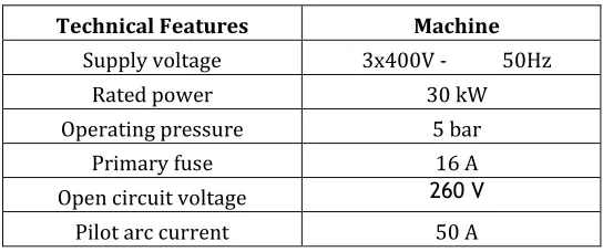
Table 3.3 Technical Features
Digital Weight Balancer
The weight of the work pieces (specimens) before and after the cutting process need to be measured in order to obtain the amount of Material Removal Rate (MRR).
Surface Roughness Tester
There are five steps to measure the surface roughness of specimens. Firstly, clamp the work piece of project use a clamping in the machine. And then, setting a prop of axis likes up and down, right or left direction. After finish setting, can start measured a work piece. Lastly, a data value for roughness can print out after finish measured.
The surface roughness tester (FORM TALY SURF) used in this work, with the following specifications:
Manufacturer: Taylor Hobson, U.K, Travelling length: 01mm-50mm, Force: 4mN,
Stylus: Diamond 2µm tip radius, Resolution: 16nm/1.0mm,
Software: Form ultra software
Power Supply
The power supply required depends on the material thickness and cutting speeds desired. Increasing the power increases the cutting speed or enables thicker metals to be
cut without slow down. Power ratings are commonly between 20 and 200 kW.
Technical Features Machine
Supply voltage 3x400V - 50Hz Rated power 30 kW Operating pressure 5 bar
Primary fuse 16 A Open circuit voltage 260 V
© 2019, IRJET | Impact Factor value: 7.211 | ISO 9001:2008 Certified Journal | Page 2738
Fig. DC Power Supply Source
DESIGN FACTORS
Design of Experiments technique has been utilized to obtain the best combination of design factors to achieve optimum performance measures. Plasma Arc Cutting involves several input parameters to be considered during machining process. In this thesis, the combination factors such as Gas Pressure [bar], Current Flow Rate [A], Cutting Speed [mm/min] and Arc Gap [mm] are considered. These factors are the most important to have the best value for Material Removal Rate (MRR) and Surface Roughness (Ra) when cutting material like Stainless Steel or Nickel Base A
3. DATA COLLECTION AND RESULTS
16 test specimens having dimension 30mm x 30mm x 12 mm were prepared for the experimental work.
The material for test specimen was Stainless Steel ASTM A 240 TP 316 L. Here L stands for Low Carbon Content.
Fig. Test Specimen
EQUIPMENTS
Equipment for the experiment use is:
Plasma arc cutting system Silvering Make with Sharpline Bombay make Burny 10 LCD
[image:6.612.208.415.465.608.2]© 2019, IRJET | Impact Factor value: 7.211 | ISO 9001:2008 Certified Journal | Page 2739
The surface roughness tester (FORM TALY SURF) Taylor Hobson Make (U.K.)
Result
The Optimum levels of parameters for maximizing MRR are A1 B2 C2 D2 i. e. Gas Pressure: 5 Bar
Current: 150 A
Cutting Speed: 600 mm/min Arc Gap: 4mm
The optimum levels of parameters for minimizing Surface Roughness (Ra) are A2 B2 C1 D1 i. e.
Gas Pressure: 6 Bar Current: 150 A
Cutting Speed: 400 mm/min Arc Gap: 2 mm
[image:7.612.101.510.427.661.2]After performing experiment as per given optimum levels for MRR and SR following results obtained:
Table Results Before and After Optimisation
So we can say that there is 0.81% improvement in MRR and also Surface Roughness reduce with 5.91%. This finding indicated that the experiments in this study possess excellent repetitiveness and great potential for future reference.
EXPERIMENTAL RESULTS FOR MRR
Graph :Effects of various factors on S/N Ratio of MRR
By using MINITAB software we obtain some interactions if we look at the graph we will observe that with increase in Gas Pressure MRR S/N ratio is decreasing. Material removal rate increases with increase in Current, Cutting Speed and Arc gap.
MRR (g/sec) Predicted value of
A1B2C2D2 = 0.8264 Experimental result of A1B2C2D2=0.8331 Percentage = 0.81% Surface Predicted value of A2B2C1D1 =
© 2019, IRJET | Impact Factor value: 7.211 | ISO 9001:2008 Certified Journal | Page 2740
EXPERIMENTAL RESULTS FOR SURFACE ROUGHNESSGraph : Effects of various factors on S/N Ratio of SR
Above graph represent the effect of parameters on Surface Roughness. It can be seen that as value of Gas Pressure and Current increases, S/N ratio of Surface roughness also increases. However S/N ratio of Surface roughness decreases with increase in the Cutting Speed and Arc Gap.
CONCLUSIONS:
This thesis has presented an application of the Taguchi method to the optimization of the machining parameters of Plasma Arc Cutting Machine. As shown in this study, the Taguchi method provides a systematic and efficient methodology for determining optimal parameters with far less work than would be required for most optimization techniques. The confirmation experiments were conducted to verify the optimal parameters. It has been shown that Material Removal Rate (MRR) and Surface Roughness (Ra) can be significantly improved in the Plasma Arc Cutting process using the optimum level of parameters.
Plasma Arc Cutting Machine is widely utilized in BHEL, Bhopal to cut materials such as Stainless Steel and Nickel-Base Alloys. This is the basis work where Plasma Arc Cutting was utilized to perform the material removal process at finishing stage. The Plasma Arc Cutting (PAC) machining of Stainless Steel (316L) has been performed with the application of combination with design of experiment (DOE).The PAC parameters studied were how to have setting for the parameter such as Gas Pressure, Current flow, Cutting Speed and Arc gap of machine.
From ANOVA of MRR we can say that some parameters are not making any significant effect .This is because we must take large number of observations either by considering L27 0r L32 orthogonal array with 3 level designs.
Mathematical equation for MRR of first order is of R-sq of 71.2% and for Surface Roughness (Ra) is of R-sq 77.5% which is acceptable.
Signal-to-noise: Smaller is better
© 2019, IRJET | Impact Factor value: 7.211 | ISO 9001:2008 Certified Journal | Page 2741
REFERENCES: Journals Referred:
Joseph C. Chen, Ye Li (2009) Taguchi Based Six Sigma Approach to Optimize Plasma Arc Cutting Process: an Industrial Case Study. International Journal of Advanced Manufacturing Technology 41:760-769.
Asiabanpour Bahram (2009) Optimising the automated plasma cutting process by design of experiments. Int. J. Rapid Manufacturing, Vol. 1, No. 1,2009.
Mahapatra S S, Patnaik Amar (2006) Optimization of wire electrical discharge machining (WEDM) process parameters using Taguchi method. International Journal of Advanced ManufacturingTechnology.
Hatala Michal Faculty of Manufacturing Technologies of the Technical University of KošiceŠtúrova The Principle of Plasma Cutting Technology and Six Fold Plasma Cutting. 5th International MultidisciplinaryConference.
Mahapatra S S (2007) An evolutionary approach to parameter optimisation of submerged arc welding in the hard facing process 462 Int. J. Manufacturing Research, Vol. 2, No. 4, 2007.
Uttarwar S S, Chopade I K, Effect Of Voltage Variation On MRR For Stainless Steel EN Series 58A (AISI 302B) In Electrochemical Machining: A Practical Approach. 2OHProceedings of the World Congress on Engineering 2009 Vol II WCE 2009, July 1 - 3, 2009, London,U.K.
Hussain Altaf (2010) Surface Roughness Analysis in Machining of GFRP Composites by Carbide Tool (K20). European Journal of ScientificResearch. ISSN 1450-216X Vol.41 No.1 (2010), pp.84-98.
LajisMohammdAmri (2009) The Implementation of Taguchi Method on EDM Process of Tungsten Carbide. European Journal of Scientific Research ISSN 1450-216X Vol.26 No.4 (2009),pp.609-617.
Kandananond Karin (2009) Characterization of FDB Sleeve Surface Roughness Using the Taguchi Approach. European Journal of Scientific Research ISSN 1450-216X Vol.33 No.2 (2009),pp.330-337
Abdul KadirGullu, UmutAtici (2006) Investigation of the Effects of Plasma Arc Parameters on the Structure Variation of AISI 304 and St 52 Steels. International Journal of Material and Design 27:1157-1162
ASTM Standard Designation: A 240/A 240M-09a. Standard Specification for Chromium and Chromium-Nickel Stainless Steel Plate, Sheet, and Strip for Pressure Vessels and for GeneralApplication.
Tarng Y S, Yang W. H. (1998) Application of the Taguchi Method to the Optimization of the Submerged Arc Welding Process. Journal of Material and Manufacturing Processes,13:3,455-467
Uey-JiuhTzou, Ding Yeng Chen (2006). “ Application of Taguchi Method in the Optimization of Cutting Parameters for Turning Operation” Lunghwaniversity of Science and Technology, Taiwan (R. O.C.)
Martikainen, J.K.,andMoisio,T.J.I.(1993).Invetigation of the effect of welding parameters on weld quality of plasma arc keyhole welding ofstructural steels,Welding Journal 72(7): 329-340
Lin, J.L. and Lin, C.L. (2001). The Use of the Orthogonal Array with Grey Relational Analysis to Optimize the Electrical Discharge Machining Process with Multiple Performance Characteristics, Journal of Machine Tools Manufacture.
Books Referred:
Roy, R.K. (2001).Design of Experiment Canada: John Wiley &Sons,Inc.
© 2019, IRJET | Impact Factor value: 7.211 | ISO 9001:2008 Certified Journal | Page 2742
Design of Experiment Manual. Minitab 15 StatisticalSoftware. Plasma Arc Cutting Theory, Miller Electric Mfg. Co.Publication.
Ross J. Philip (2008) Taguchi Techniques for Quality Engineering 4th Edition Tata Mcgraw HillPublication.
Montgomery C. Douglas (2007) Design and Analysis of Experiments 5th Edition: John Wiley & Sons, Inc; p.76-86
Kalpakjian, S & R Schmid, S.(2000).Manufacturing Engineering and Technology:4th Edition UK: Prentice-Hall, Inc; p.164-165
Jeffus Larry (2003). Welding Principles and Applications: Sixth Edition: Inc; p.182-203.
Websites:
Plasma Cutting,http://en.wikipedia.org/wiki/Plasma_cutting
PlasmaEquipment,http://www.answers.com/topic/plasma-torch?cattechnology
Benefits Of Plasma Arc Cutting,http://www.airgas.com
http://www.aws.org/wj/2003/02/024/#A,
Plasma(Physics),http://en.wikipedia.org/wiki/Plasma_(physics)#History
PlasmaCutting,
http://www.lincolnelectric.com/knowledge/articles/content/plasma.asp
PlasmaCutting, http://www.esab.com/global/en/education/processes-plasmacutting.
Cutting Process,http://www.twi.co.uk/j32k/protected/band_3/jk51.html
Cutting Torch,http://www.welding-advisers.com/Cutting-torch.html
Quality,http://www.centricut.com/TA_CutQualityProblems.htm,4 April2008
Technical System Consideration,http://tristate.apogee.net/et/eftcpat.asp
Plasma Cutting,http://www.hypertherm.com/technology.htm
Roughness,http://en.wikipedia.org/wiki/Roughnesshttp://home.howstuffworks.com/plasma-cutter1.htm