Abstract—The objective of inverse halftoning is to reconstruct high quality grayscale images from bi-level halftone images. Different from the previous inverse halftoning approaches, our algorithm computes the difference image between the predicted image using Gaussian filtering from a halftone image and the original grayscale one. The difference image is then compressed and embedded into the halftone image using a reversible data hiding method. In the image reconstruction process, the marked halftone image is scanned to extract the embedded data. Finally, a better quality of reconstructed image can be generated by adding the extracted difference image to the predicted image. Experimental results show that the proposed approach can efficiently improve the quality of reconstructed images for inverse halftoning when compared to the previous approaches.
Index Terms—inverse halftoning, pattern substitution, reversible data hiding, Gaussian filtering
I. INTRODUCTION
ALFTONE techniques have been widely applied to many fields, including the printing of newspapers, magazines, books, and display devices. It is a process of converting grayscale images into halftone images for the devices that can only process bilevel images. Halftone images are binary images that provide a rendition of gray-scale images and consists of „0” and „1”. In the halftoning process, it needs to use a kernel to carry out the conversion, and the common kernel is such as Floyd-Steinberg kernel, and is difficult to recover a continuous-tone image through halftone manipulation, conversion, compression, etc. Inverse halftoning is a process which transforms halftone images into grayscale images. The objective of inverse halftone reconstruction is to convert halftone bilevel images into gray-level images with the minimum distortion. In the past few years, many efficient inverse halftoning algorithms have been proposed, but there is no way to construct a perfect gray-scale image from a given halftone image. There exist several inverse halftoning methods, including kernel estimation [1], wavelet [2], filtering [3][4], and set theoretic approaches[5]. Most of these methods can obtain good Manuscript received March 19, 2011; revised April 15, 2011. This work was Mei-Yi Wu. Author is with General Education Center, National Kaohsiung University of Hospitality and Tourism. No.1, Songhe Rd., Xiaogang Dist., Kaohsiung City 81271, Taiwan (e-mail:barbara
@mail.nkuht.edu.tw)
Jia-Hong Lee. Author is with Information Management Department, the National Kaohsiung First University of Science and Technology, 2 Jhuoyue Rd., Nanzih, Kaohsiung City, 811, Taiwan (corresponding author, phone:
886-7-6011000; fax: 886-7-6011069; e-mail: jhlee@ nkfust.edu.tw).
Hong-Jei Wu. Author is with Information Management Department, the National Kaohsiung First University of Science and Technology.
.
reconstruction image quality but require relatively high computational complexity.
The halftoning and inverse halftoning processes can be regarded as the encoding and decoding processes of vector quantization. Therefore, the codebook design methods can be applied to build the inverse halftoning lookup tables [6] [7].
The content of a table entry is the centroid of the input samples that are mapped to this entry. The results are optimal in the sense of minimizing the MSE for a given halftone method. Although the table lookup method has the advantages of good reconstructed quality and fast speed, it faces the empty cell problem in which no or very few training samples are mapped to a specific halftone pattern.
In this paper, a reversible data hiding scheme is proposed to embed some “useful” information into the halftone images.
Then users can extract the embedded information and reconstruct the original halftone image from the marked halftone image. The extracted information can improve the quality of generated grayscale images by using a filter based inverse halftoning method.
II. REVIEW OF INVERSE HALFTONING AND REVERSIBLE DATA HIDING
A. LUT-based Inverse Halftoning (LIH) Method
The LUT-based method includes two procedures: the LUT build-up and the LUT-based inverse halftoning (LIH) procedures. The LUT build-up procedure is to build the LUT information by scanning selected grayscale images and their corresponding halftone images with a 3×3 or 4×4 template.
Template is used as a sliding window to build up the LUT. In the LIH procedure, a grayscale image can be reconstructed from a given halftone image using the LUT information. The LUT information contains a set of pairs of binary pattern and its corresponding estimated gray value. Assume that there are
Ltraining image pair sets and{(O,H)|1 i L}
i
i represents the ith pair, where Oi denotes the ith original image and Hi the corresponding halftone image ofOi. The LUT build-up and LIH procedures using 4×4 template F are described as follows:
Procedure LUT build-up:
Step 1: Let arrays LUT[] and N [] be zero as the initial values.
LUT[] is used to record the mapped gray value corresponding to a specific binary template with index I which is appeared in the input halftone image and N[] is used to store the occurrence frequency of this specific binary template in the halftone image. Select L training grayscale images and generate their corresponding halftone images, respectively.
Inverse Halftoning Method Using Pattern Substitution Based Data Hiding Scheme
Mei-Yi Wu, Jia-Hong Lee and Hong-Jie Wu
H
Step2: Select one image from the L training grayscale images.
Scan the selected image and its corresponding halftone image in raster order with the template F. Let Pk be the binary value of a pixel located on X in a halftone image and the gray value with the same locaton X in a training image is denoted as G(X). The index I and LUT[I] can be calculated using equation (1) where k represents different location on the template F. Since there are totally 16 locations on the template F, the value of I ranges from 0 to 65535. Then, the sum of the template occurrence frequencies and the sum of the gray values on the training image with the same position X can be computed as the equation (2).
k k
KP
I
15
0
2 (1)
) ( ] [ ] [
1 ] [ ] [
X G I LUT I LUT
I N I N
(2)
Step3: Repeat Step 2, until all L images are selected.
Step4: The predicted gray value for a specified 4×4 pattern with indexed I can be computed as
] [ ] ] [
[I LUTI NI
LUT (3)
Procedure LIH:
Step1:Perform the above-mentioned LUT build-up algorithm to build LUT.
Step2: Scan a halftone image in raster order with template F, and compute the template index I using equation (1).
The estimated gray value G‟(X) on the location X can be obtained and denoted asG'(X)LUT[I].
Step3: Output the estimated grayscale image.
Note that, some binary patterns in the input halftone image may not exist in the training images. In this situation, we will apply Gaussian filter method to estimate the mean gray value.
Thought the LUT-based inverse halftoning method is easily implemented, there exists a disadvantage of this method, the constructed LUT information must be sent to the receiver.
B. Gaussian Filtering Method
Gaussian filtering is a smoothing algorithm for images.
Equation (4) denotes a 2D Gaussian function, where is the standard deviation of a Gaussian distribution. In the implementation of inverse halftoning using Gaussian filtering, the binary pixel value 0 and 1 in the input halftone image will be regarded as 0 and 255, respectively. A weight mask with specified size and contents should be determined according to the use of Gaussian distribution with parameter .
2 2 2 2
2 2
) 1 ,
(
y x
e y
x G
(4) In the inverse halftoning process, the halftone image is scanned pixel by pixel in a raster order by moving the sliding mask. The output gray value on the corresponding central pixel of the mask is estimated via the summation of the weight value on the mask content multiplying by the binary values on the neighboring pixels.
III. THE PROPOSED METHOD A. Diagram of the Proposed Method
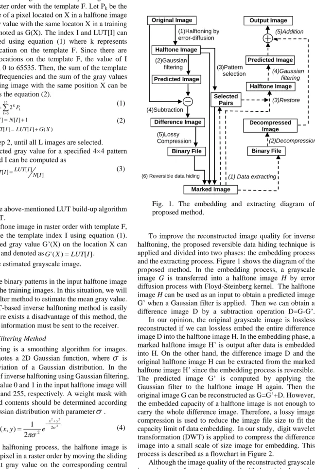
Fig. 1. The embedding and extracting diagram of proposed method.
To improve the reconstructed image quality for inverse halftoning, the proposed reversible data hiding technique is applied and divided into two phases: the embedding process and the extracting process. Figure 1 shows the diagram of the proposed method. In the embedding process, a grayscale image G is transferred into a halftone image H by error diffusion process with Floyd-Steinberg kernel. The halftone image H can be used as an input to obtain a predicted image G‟ when a Gaussian filter is applied. Then we can obtain a difference image D by a subtraction operation D=G-G‟.
In our opinion, the original grayscale image is lossless reconstructed if we can lossless embed the entire difference image D into the halftone image H. In the embedding phase, a marked halftone image H‟ is output after data is embedded into H. On the other hand, the difference image D and the original halftone image H can be extracted from the marked halftone image H‟ since the embedding process is reversible.
The predicted image G‟ is computed by applying the Gaussian filter to the halftone image H again. Then the original image G can be reconstructed as G=G‟+D. However, the embedded capacity of a halftone image is not enough to carry the whole difference image. Therefore, a lossy image compression is used to reduce the image file size to fit the capacity limit of data embedding. In our study, digit wavelet transformation (DWT) is applied to compress the difference image into a small scale of size image for embedding. This process is described as a flowchart in Figure 2.
Although the image quality of the reconstructed grayscale image is not perfect when compared with the original one, the obtained image quality is better than the traditional inverse halftoning methods.
Original Image
(1)Halftoning by error-diffusion
(2)Gaussian filtering
(5)Lossy Compression
(1) Data extracting (6) Reversible data hiding
(3)Pattern selection Halftone Image
Predicted Image
Difference Image
Binary File
Selected Pairs
Marked Image
Binary File Decompressed
Image Halftone Image Predicted Image Output Image
(3)Restore
(2)Decompression (4)Gaussian
filtering
(4)Subtraction
(5)Addition
Fig. 2. The process of generating a difference image.
B. Reversible Data Hiding for Binary Images
Reversible data hiding can embed secret message in a reversible way. Relatively large amounts of secret data are embedded into a cover image so that the decoder can extract the hidden secret data and restore the original cover image without any distortion. Recent, a boundary-based PWLC method is presented [8]. This method defines the same continuous 6 edge pixels as an embeddable block through searching for binary image edges. And then one can embed data in the pair of the third and fourth edge pixels. A reversible data hiding method for error diffused halftone images is proposed[9] (Pan, Luo & Lu, 2007). This method employs statistics feature of pixel block patterns to embed data, and utilizes the HVS characteristics to reduce the introduced visual distortion. The method is suitable for the applications where the content accuracy of the original halftone image must be guaranteed, and it is easily extended to the field of halftone image authentication. However, these two methods both have a drawback that the capacity of data hiding is still limit.
Recently, Ho et al. [10] proposed a high-capacity reversible data hiding method for binary images using pattern substitution. The method is capable of both successful extraction of secret data from a stego-image and restoring the binary image completely after the extraction of secret data.
Their method gathers statistical data concerning the occurrence frequencies of various patterns and establishes the pattern exchange relationships. Pattern substitution can be used according to the pattern relationships for data hiding. In this paper, Ho‟s scheme is applied to embed some “useful”
information into the halftone images and the information can be extracted and used to improve the quality of generated grayscale images. The flowchart of Ho‟s method is displayed in Figure 3.
Fig. 3. The flowchart of data embedding process in Ho‟s method.
It is not discernible to human eyes if we modify or add a pixel on the edge of a binary image. Therefore, the image flipping operation of Ho‟s method is to find the boundaries where black and white pixels meet. The flipping formula is as follows.
) 1 , ( ) , (
) , 1 ( ) , (
) , ( ) , (
i j P j i P
i j P j i P
j i P j i D
otherwise
i and j
if
i and j
if
1 1
1 1
(5)
For a flipped image, we divide it into non-overlapped 4×1 image blocks. Each four-pixel block from the flipped image can be regarded as a pattern. Then we can compute the occurrence frequencies for each kind of pattern type. TABLE I is the computed results for Lena image.
In this study, we modified Ho‟s method to embed more capacity. All patterns are classified into two groups, high frequent pattern and low frequent pattern. For each high frequent pattern A, a low frequent pattern B which content is the most closest to pattern A will be selected to form a pair for data embedding. In the data embedding process, the original halftone image is partitioned into a group of 4×1 non-overlapping patterns. Then, any pattern p on the halftone image with the same content of A will be selected to embed 1-bit data. If a data bit “0” is embedded on p, then the content of p is remained as A. If a data bit “1” is embedded on p, then the content of p is updated as the content of pattern B. In data extraction process, the embedded message is obtained depending on the pattern A, B when the test image is scanned.
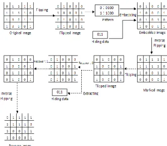
For example, assume that the highest frequent pattern in the image is PH=1111 and its corresponding lowest frequent pattern is PL=0101. If the content of the pattern PH is encountered, then check the bit value which is currently embedded. If the bit value is “0” then remain the content as PH. If the value is “1” then we replace PH with the PL pattern.
Figure 4 shows an example of the data embedding and extracting processes for the used method. However, we had found that the usage of pattern type with PL=0000 would cause “black spot” effect in the marked image. Therefore, we avoid the selection of this pattern type in the data embedding process. Figure 5 is an example to demonstrate the results with and without the usage of pattern type PL=0000. TABLE I shows the frequencies of different 4×1 patterns appeared in Lena Image of size 512×512.
TABLE I
THE FREQUENCIES OF DIFFERENT PATTERNS APPEARED IN LENA IMAGE
Pattern type Frequency Pattern type Frequency
P0000 4615 P0001 2115
P0011 3620 P0010 103
P1100 244 P1000 122
P1001 5281 P1001 4486
P1010 1526 P1110 2226
P0101 230 P0101 6068
P0110 3600 P1101 6072
P1111 20913 P1011 4315
Cover image Image flipping
Pattern selection for modification
Capacity computation
Hiding by key Pattern
substitution Bit stream
Secret data
Marker image
Fig. 4. The processes of data embedding/extracting for the used reversible data hiding scheme.
(a) (b)
Fig. 5. Marked images of the data embedding (a)using the pattern type PL=0000 (b) without using the pattern type PL=0000.
For the purpose of reversibility, we should record the coordinates of the used lowest frequent patterns appeared in the test image. In addition, to achieve a higher capacity of embedding data, more pattern pairs should be determined, whose steps can be presented as below.
Procedure-Pair Selection and Pattern Substitution method for halftone images
Step1. Partition the original image into non-overlapping 4×1 blocks.
Step2. Compute the occurrence frequencies for all appeared patterns. Sort these patterns decreasingly and denoted them asPHi according to their occurrence frequencies.
Step3. Find out all low frequent patterns PL. Assume that there are totally k low frequent patterns, k pairs of patterns (PHi,PLi) should be constructed to perform the data embedding. Here the pattern matching operation should follow the minimum distance rule and the benefit rule, where the distance computation of two patterns is defined as
3
0
) , (
t
t
t PL
PH PL
PH
Dist (6) The embedding capacity benefit of the ith pair of pattern
with pattern type PHt and PLt is determined by the following equation.
) 4 18
* (#
)
#
(#
t t t
i PH PL PL
Benifit (7) where #PH and #PL is the frequencies of the high and
low frequent pattern appeared in the image, and the overhead is for keep the coordinates of the PL patterns (9 bits for x coordinate and 9 bits for y coordinate if the size of the test image is 512×512) and the PL content.
Step 4. Search all blocks in the original image. As long as we come across a pattern in thePHi , if a bit “0” is embedded, the block is remained as PHi; Otherwise the block is updated as the patternPLi.
The distance definition for two patterns in equation 1 means the count of different appearance in the same positions on patterns. The Maximum capacity for different halftoned images using the proposed method is listed as follows.
TABLE II
The Maximum Capacity of the embedding method Image Maximum Capacity(bits)
Lena 27849
Pepper 26612
Airplane 14849
Baboon 6912
C. Overhead Information
There are two kinds of data should be embedded into the halftone image to achieve the reversible data hiding and the high quality of recovery image, they are the selected pairs information (SH) and the compressed difference image(DH), respectively. In the data extraction process, the receiver should know the predefined patterns (PHi,PLi) in the data embedding process to extract data correctly. Assume that there are totally TC pairs of patterns used in the data embedding process, the following data depicted in Figure 6(a) should be embedded sequentially. The size the overhead information is 3 + 9×2×TC bits. We use 3 bits to store the TC value since the total count of pattern pairs for 4×1 different binary patterns is 16=2×23. On the other hand, assume the compressed file size of the difference image is DH, the compressed file of the difference image is arranged in bit streams for embedded into the halftone image after the embedding of pair information. The data structure is shown in Figure 6(b).
TC PH0 PL0 … PHTC1 PLTC1
(a) SH (selected pair header)
DH D'0 D'1 … D'DL2 D'DL1
(b) DH (Data header)
Fig. 6. The data structures of the overhead information: (a) pairs information and (b) the compressed image information.
D. Data Embedding and Extracting
The way to embed SH information is important since the receiver cannot extract any data from the marked images if he doesn‟t have the SH information before data extracting. We divided the halftone image into two regions: one is the place to embed SH sequence and the other one is the place to embed the DH sequence. Since the size of SH information is very small when compared to the entire image size. Two kinds of embedding data can be chosen here. One is the fixed position method to arrange the SH and DH in faxed regions, such as the example in Figure 7(a) and the other is the random position method to randomly select different pixels for embedding DH information. Then we directly replace the selected pixels with the SH sequence. The implementation of the second method requires a secret key K to select the positions for embedding SH sequence and the receiver should also have the key to extract the data. Although the second method needs more computation in SH embedding, it owns a higher security than the first method.
Fig. 7. Two kinds of methods to embed SH and DH.
The block diagram of data extraction is shown in Figure 1, with steps as follows.
Procedure-Data Extraction from a marked halftone image Step1. The SH and DH sequence reconstruction: we use the
same Key K to find the 3 + 9×2×TC pixel locations and arrange the pixel values into the selected pattern pairs (PHi,PLi). Extract the embedded DH sequence by scanning the entire image according to the SH information. If a pattern in the PHi is found then output bit 0. If a pattern in the pattern PLiis found then output bit 1.
Step2. Decompression: DH sequence is decoded using inverse digital wavelet transform (IDWT) and a predicted difference image D‟ is obtained.
Step3. Restore the original halftone image H: The scan of the whole marked image is performed. If a pattern belongs to the pattern PLi then replace the pattern with the corresponding patternPHi. Then, we will update a part of patterns PHi using the coordinate information of all original PLi extracted from SH.
Step4. Compute the predicted image G‟: A predicted image of the halftone image H is output using a Gaussian filter.
Step5. Image reconstruction: A recovery image is obtained by adding the image D‟ to the predicted image G‟.
IV. EXPERIMEANT RESULTS
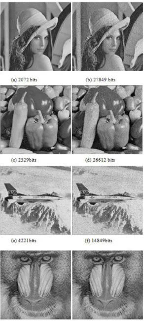
Four 512× 512 error diffused halftone images, Lena, Baboon, Airplane, and Pepper are selected to evaluate the performance of the proposed method, as shown in Figure 8.
These halftones are obtained by performing Floyd–Steinberg error diffusion filtering on the 8-bit gray-scale images.
Comparison of different inverse halftoning methods, including Gaussian filtering, LIH, ELIH are implemented.
The PSNR values of the predicted image from different inverse halftoning method and the original grayscale image are computed as listed in Table III. The marked images of the proposed methods are shown in Figure 8.
Fig. 8. The marked images with different amount of data bits embedded using the proposed method.(a)(c) two pairs of patterns were used (e)(g)three pairs of patterns were used;(b)(d)(f)(h) maximum capacity of data were embedded.
In addition, image quality of restored grayscale images was evaluated.
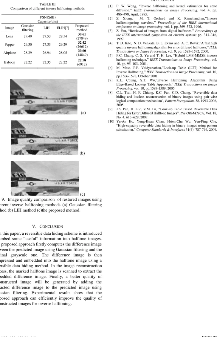
Three sub-images extracted from the restored images using different inverse halftoning methods are shown in Figure 9.
We can found that the print words in the reconstructed image in Figure (c) look clearer than the other two methods.
TABLE III
Comparison of different inverse halftoning methods PSNR(dB)
Capacity(bits) Image Gaussian
filtering LIH ELIH[7] Proposed method
Lena 29.40 27.53 28.54 30.61
(27849)
Pepper 29.30 27.33 29.29 32.42
(26612) Airplane 28.29 26.94 28.05 30.60
(14849)
Baboon 22.22 22.35 22.22 22.58
(6912)
(a)
(b)
(c)
Fig. 9. Image quality comparison of restored images using different inverse halftoning methods (a) Gaussian filtering method (b) LIH method (c)the proposed method.
V. CONCLUSION
In this paper, a reversible data hiding scheme is introduced to embed some “useful” information into halftone images.
The proposed approach firstly computes the difference image between the predicted image using Gaussian filtering and the original grayscale one. The difference image is then compressed and embedded into the halftone image using a reversible data hiding method. In the image reconstruction process, the marked halftone image is scanned to extract the embedded difference image. Finally, a better quality of reconstructed image will be generated by adding the extracted difference image to the predicted image using Gaussian filtering. Experimental results show that the proposed approach can efficiently improve the quality of reconstructed images for inverse halftoning.
REFERENCES
[1] P. W. Wong, “Inverse halftoning and kernel estimation for error diffusion,” IEEE Transactions on Image Processing, vol. 4, pp.
486–498, April, 1995.
[2] Z. Xiong, M. T. Orchard and K. Ramchandran,”Inverse halftoningusing wavelets,” Proceedings of the IEEE international conference on image processing, vol. 1, pp. 569–572, 1996.
[3] Z. Fan, “Retrieval of images from digital halftones,” Proceedings of the IEEE international symposium on circuits systems pp. 313–316, 1992.
[4] T. D. Kite, N. D. Venkata, B. L. Evans and A. C. Bovik,”A fast high quality inverse halftoning algorithm for error diffused halftones,” IEEE Transactions on Image Processing, vol. 9, pp. 1583–1592, 2000.
[5] P.C. Chang, C. S. Yu and T. H. Lee, “Hybrid LMS-MMSE inverse halftoning technique,” IEEE Transactions on Image Processing, vol.
10, pp. 95–103, 2001.
[6] M. Mese, P.P. Vaidyanathan,”Look-up Table (LUT) Method for Inverse Halftoning,” IEEE Transactions on Image Processing, vol. 10, pp.1566-1578, October 2001.
[7] K.L. Chung, S.T. Wu,”Inverse Halftoning Algorithm Using Edge-Based Lookup Table Approach,” IEEE Transactions on Image Processing, vol. 10, pp.1583-1589, 2005.
[8] C.L. Tsai, H. F. Chiang, K.C. Fan, C.D. Chung, “Reversible data hiding and lossless reconstruction of binary images using pair-wise logical computation mechanism”, Pattern Recognition, 38. 1993-2006, 2005.
[9] J.S. Pan, H. Luo, Z.M. Lu, “Look-up Table Based Reversible Data Hiding for Error Diffused Halftone Images”. INFORMATICA, Vol. 18, No. 4, 615–628, 2007.
[10] Yu-An Ho, Yung-Kuan Chan, Hsien-Chu Wu, Yen-Ping Chu,
“High-capacity reversible data hiding in binary images using pattern substitution.” Computer Standards & Interfaces 31(4): 787-794, 2009.