Integrating Reactive Systems Design
in Systems of Systems Framework
R. Guillerm and A. Sahraoui
Abstract—As technology advances, systems perform more
functions and become more interconnected. The result is an
increasing level of complexity. Those charged with acquiring such
systems need to ask whether or not they have the right skills to
successfully complete them. A comprehensive technique is
proposed for addressing reactive systems, such technique is based
on systems engineering concepts. The work is illustrated through
two systems engineering standard as IEEE P1220 and ANSI-EIA
632.
Index Terms Reactive systems; systems engineering deployment; systems of systems; systems engineering standards; IEEE-P1220; ANSI-EIA-632.
I. INTRODUCTION:ABOUTSYSTEMSOFSYSTEMS
FRAMEWORK,NEEDSANDREQUIREMENTS
In [1], a roadmap in SE research and mainly on systems families (known as systems of systems), it is explained that large systems are often formed from a variety of component systems: custom systems that are newly engineered from the “ground up”; existing commercial-off-the-shelf (COTS) systems, which are custom tailored for a particular application; and existing or legacy systems. Such related terms as systems of systems (SOS), federations of systems (FOS), federated systems of systems (F-SOS), and coalitions of systems (COS) are often used to characterize these systems. These appellations capture important realities brought about by the fact that modern systems are not monolithic. Rather, they have five characteristics initially well summarized by Mark Maier (1998) that make one of the system family designations appropriate:
1) Operational independence of the individual systems. A system of systems is composed of systems that are independent and useful in their own right. If a system of systems is disassembled into the constituent systems, these constituent systems are capable of independently performing useful operations by themselves and independently of one another.
R. Guillerm and A. Sahraoui are with LAAS-CNRS, 7 avenue du Colonel Roche,
F-31400 Toulouse, France, Univ de Toulouse;UTM; LAAS, F-31100 Toulouse,
France (email : [email protected])
2)Managerial independence of the systems. The component systems not only can operate independently, but generally they do operate independently in order to achieve the technological, human, and organizational purposes of the individual unit that operates the system.
These component systems are generally individually acquired, serve an independently useful purpose, and often maintain a continuing operational existence that is quite independent of the larger system of systems. 3) Geographic distribution. Geographic dispersion of the constituent systems in a system of systems is often quite large. Often, these constituent systems can readily exchange only information and knowledge with one another, and not substantial quantities of physical mass or energy.
4) Emergent behavior. The system of systems performs functions and carries out purposes that do not reside uniquely in any of the constituent systems. These behaviors arise as a consequence of the formation of the entire system of systems and are not the behavior of any constituent system. The principal purposes supporting engineering of these individual systems and the composite system of systems are fulfilled by these emergent behaviors.
5) Evolutionary and adaptive development. A system of systems is never fully formed or complete. Development of these systems is evolutionary and adaptive over time. Structures, functions, and purposes are added, removed, and modified as experience of the community with the individual systems and the composite system grows and evolves.
II. THEREACTIVESYSTEMS:SYSTEMSINTEGRATION
PROBLEMS
2.1. Characterizing systems
As any information systems engineering, timing is not necessarily high level criteria but the reactivity of system in a global environment. In this respect, embedded real-time systems must react continuously to stimuli from their environment. Therefore, their control-flow patterns differ from those of traditional systems that transform a given input to an output at their own pace. Reactive processors provide direct hardware support for reactive control flow, which keeps executables fast and compact and results in lower power consumption compared to traditional architectures.
environment by generating corresponding outputs. The programming of reactive systems typically requires the use of non-standard control flow constructs, such as concurrency and exception handling. Most programming languages, including languages such as C and Java that are commonly used in embedded systems, either do not support these constructs at all, or their use induces non-deterministic program behavior, regarding both functionality and timing. Furthermore, the concurrent behavior of reactive programs is typically very fine-grained. Measurements indicate that it is not uncommon to have a context switch after, on average, fewer than five instructions. This makes traditional context switch mechanisms, based on an operating system that consumes thousands of instructions per context switch, impractical.
2.2. The general framework
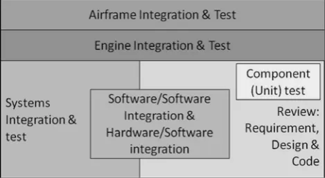
[image:2.595.50.285.351.480.2]A lot of work has been carried in systems integration through SoS framework and many application for systems design as at aircraft engine (Roll Royce) by [2] as illustrated in figure 1.
Fig. 1. General framework of integration and test for aircraft engine
From such experience (Pickard and Paisley) proned the following statement which is fundamental in systems integration in general concerning such issue “From the analysis, we noticed that component testing (testing single software code modules) in general did not find any error types that could not have been found by other means e.g. code reviews. However, the cost to find an error by component testing was nearly 100 times more expensive then code review. If a project wanted to optimize its costs and timescales the intelligent option would be to minimize component testing. Note that component testing does gather product certification data that cannot be gathered by any other means and is therefore required during certification BUT can be optimized out during development.
Similarly, it was noticed that software/software integration testing and hardware/software integration testing found very similar error types. It would be possible to omit one method OR optimize the use of the methods depending on the aspects of the system under test e.g. hardware aspects to be testing with hardware integration. In principle, when
two processes find the same type of error, it is possible to select between the processes depending on the value they each bring”.
III. LEVELSOFCOMPETENCY
3.1. Missions
Often, appropriate missions exist for relatively large systems of systems in which there is a very limited amount of centralized command-and-control authority. Instead, a coalition of partners has decentralized power and authority and potentially differing perspectives of situations. It is useful to term such a system a “federation of systems” and sometimes a “coalition of systems”. The participation of the federation or coalition of partners is based upon collaboration and coordination to meet the needs of the federation or coalition. The notions of autonomy, heterogeneity, and geographic dispersion are not independent of one another. Increasing geographic dispersion will usually lead to greater autonomy and consequently also increase heterogeneity. The Internet is perhaps the best example of a system that began under the aegis of a single sponsor, the U.S. Department of Defense, and has grown to become a federation of systems.
3.2. Support for innovation
Support for innovation and change of all types is a desirable characteristic of these system families [3]. Innovation includes both technological innovation and organizational and human conceptual innovation. Accomplishing this requires continuous learning, a reasonable tolerance for errors, and experimental processes to accomplish both the needed learning and the needed change. The systems fielded in order to obtain these capabilities will not be monolithic structures in terms of either operations or acquisition. Rather, they will be systems of systems, coalitions of systems, or federations of systems that are integrated in accordance with appropriate architectural constructs in order to achieve the evolutionary, adaptive, and emergent cooperative effects that will be required to achieve human and organizational purposes and to take advantage of rapid changes in technology. They can potentially accommodate: system lifecycle change, in which the life cycle associated with use of a system family evolves over time; system purpose change, in which the focus in use of the system emerges and evolves over time; and environment change, in terms of alterations in the external context supporting differing organizational and human information and knowledge needs, as well as in the technological products that comprise constituent systems.
IV. THEAPPROACHANDASSOCIATEDTECHNIQUE
The followings steps can be implemented by using the traditional method developed in [4]:
• define processes,
• develop associated technique, • search for tools or develop if needed.
4.1. Defining the process
Here we directly make use of existing standards; our experience has been developed with ANSI-EIA 632. We focus our work on the three main processes: system design (with the requirements and the solution definitions), product realization (with the implementation), and technical evaluation (with the verification and validation).
For the requirements in reactive systems, we have to set up the general architecture between the final product as part of general systems: reactive systems is subsystems with its own enabling product. At this level we have to take into consideration the systems views and application software view, even we may consider the co-design issue at the later step.
The same follow for implementation, and validation and verification.
4.2. Develop associated technique for reactive systems requirements design and verification/validation
It is at the level where the techniques are addressed depending to each process.
Two leading alternative approaches to the grand design approach for the engineering of systems were initially termed incremental and evolutionary, although the term evolutionary is now generally used to characterize both of these.
1) In incremental development, the system is delivered in pre-planned phases or increments, in which each delivered module is functionally useful. The overall system capability improves with the addition of successive modules. The desired system capability is planned to change from the beginning, as the result of “build N” being augmented and enhanced through the phased increment of “build N+1.” This approach enables a well-functioning implementation to be delivered and fielded within a relatively short time and augmented through additional builds. It also allows time for system users to thoroughly implement and evaluate an initial system with limited functionality compared to the ultimately desired system. Generally, the notion of preplanning of future builds is strong in incremental development. As experience with the system at build N is gained, requirements changes for module N+1 may be more easily incorporated into this, and subsequent, builds.
2) Evolutionary lifecycle development technique is similar in approach to its incremental complement; however, future changes are not necessarily pre-planned. This approach recognizes that it is impossible to initially predict and set forth engineering plans for the exact nature of these changes. The system is engineered at build N+1 through reengineering the
system that existed at build N. Thus, a new functional system is delivered at each build, rather than obtaining build N+1 from build N by adding a new module. The enhancements to be made to obtain a future system are not determined in advance, as in the case of incremental builds. Evolutionary development approaches can be very effective in cases where user requirements are expected to shift dramatically over time, and where emerging and innovative technologies allow for major future improvements. They are especially useful for the engineering of unprecedented systems that involve substantial risk and allow potentially enhanced risk management. Evolutionary development may help program managers adjust to changing requirements and funding priority shifts over time since new functionality introductions can be advanced or delayed in order to accommodate user requirements and funding changes. Open, flexible, and adaptable system architecture is central to the notion of evolutionary and emergent development. These are major elements in the contemporary U.S. Department of Defense Initiatives in evolutionary acquisition and such issues as Network Centric Warfare.
4.3. The tools
Many conventional systems are special-purpose-built, as a mixture of commercial-off-the-shelf systems and custom developments of hardware and software. These constituents are generally provided by multiple contractors who are used to supporting a specific customer base and working under the leadership of a single vertical program management structure. For best operation, these systems should be managed as a system of systems, network of networks, federation of systems, or coalition of systems.
A system of systems generally has achieved integration of the constituent systems across communities of contractors, and sometimes across multiple customer bases, and is generally managed by more horizontally organized program management structures, such as integrated product and process development (IPPD) teams. When the IPPD team effort is well coordinated, the team is generally well able to deal with conflict issues that arise due to business, political, and other potentially competing interests [4].
V. MODELSPECIFICATIONMETHOD
This section describes general model-based system design
process, around architectural alternative assessment.
When developing hybrid systems in terms of mixed
mechanical, electronic equipment, there is a need for a high
level of abstraction when devising architecture. The system
view is preferred for its effectiveness in tackling such types
of systems. The choice of SysML is meant to have an
independent method rather than choosing specific technology
method; also VHDL-AMS is a general purpose notation for
for electronics systems.
During physical solution definition, some functional and
performance requirements are identified as key architecture
efficiency indicators. These indicators will be assessed by an
executable model, by translating them into a set of measurable
values on physical model. Two goals must be satisfied when
building such a model :
First, try to completely simulate parameters that have been
identified as key efficiency indicators. This corresponds to a
top-down view of the model specification, starting from high
level, stakeholder needs, and allows to ensure that purpose of
system is done according to functional specification.
Next, allow identification of unexpected or undesirable effect
that can lead to reject an architecture. This issue is tightly
linked to system internal and external interfaces, and
operating environment. As it is depends on technical solutions,
this corresponds to the bottom-up aspect of model
specification. (For example, one model does not simulate
heat transfer between two part of system, resulting in
unrealistic gas temperature in pneumatic actuator, and
therefore unrealistic operating performance).
Following steps propose a way to specify and build physical
models trying to improve efficiency and benefits of modeling
and simulation tasks.
1. Identify technical effectiveness metrics on Logical
Architecture Solutions. Architecture effectiveness metrics
should be expressed in a solution independent point-of-view.
This effectiveness metrics should be approved by stakeholders,
for example during logical solution review. In SysML, we
specify attributes to component block in order to specify
internal values that have to be simulated in the dynamic
executable model. For example, electrical consumption, speed
profile, mechanical effort). Expected discrete event properties
are specified as sequence or activity diagrams that will be
compared to simulation results (for example: aural warning
triggering, sensor measurement time).
2. Allocate effectiveness metrics on system components and
interfaces. As alternative architectures are explored, efficiency
metrics have to be translated and allocated on system parts.
Such characteristics are key performance parameters such as
effort/torque, speed, response time, hydraulic pressure...
These are considered key characteristic in that they are
directly traceable against technical efficiency criteria and
stakeholders expectations. This allocation process can be
based on engineering judgment, or based on trade-off analysis.
Exploring design alternative will usually bring to refine or
complete set of efficiency metrics previously defined. This is
not an issue as long as set of design alternatives refers to the
same efficiency metrics reference. For example, assessing
one electro-mechanical system against a human powered
system can bring designers to asses system energetic
autonomy.
3. Specifying simulation sequence and stimulus. In
conjunction with effectiveness metrics allocation, one should
define simulation conditions, stimuli, and measuring means to
ensure that simulation will provide expected benefits. This
step is tightly coupled with architecture definitions and may
require to develop some additional model parts. For example
measuring a numeric response time on a continuous signal
shall require developing a measuring component with
measured signal being compared to thresholds values and
returning required response time value.
4. Derive components internal parameters from key physical
characteristics. This task has a great impact on model
accuracy. Once key characteristics have been allocated, one
should consider component internal parameters that could
impact its key characteristics. This is actually a bottom-up
analysis, in that it highly depends on intrinsic, physical
structure of each component. It is usually performed by
engineering judgment, and requires a careful analysis of both
the component intrinsic properties and its operating
conditions and environment. For example, consider one
component as a mechanical damper used in an emergency
mechanical system. In this example efficiency metrics
naturally brings to allocate a minimum damping effort to this
component. Then, the use of a hydraulic actuator should bring
to add the oil temperature as an internal parameter to be
monitored as it has a great impact on damping effort which
will be produced.
5. Identify additional parameters to raise undesired effect
simulation. Such task should be derived by engineering
analysis such as safety and maintainability analysis. It should
key physical characteristics and internal parameter.
6. Model dynamic behavior. In this task, modeler should
ensure that instructions that models dynamic behavior covers
computation of key, internal parameters, and also particular
parameters. Depending on model abstraction level, these
instructions can be differential or algebraic, conservative or
non-conservative equations, or transfer functions.
VI. ACASESTUDY
We have an example of application for the engineering of a complex system which can be considered as a system of systems itself. In this case study, we have chosen to focus in particular on the safety properties which must be analyzed at system level.
6.1. Context
In fact, we follow the EIA-632 standard and some extra recommendations that we have defined [5]; at the process level. This recommendations detail the necessary activates for define, manage, integrate, decline, verify, and valid the safety properties, and explain at which steps (“when?”) do these activities. At the same time, we have proposed one methodology for complete some of these activities, with the use of famous safety methods (FMECA [6] and fault trees [7]); at the method level. Our approach is also accompanied by an information model [8] which uses SysML language [9]; at tool level. Indeed, as said previously, designing system of systems involves necessarily a way to share the system information between the different trades of studies (mechanical, electrical, thermal, safety…) who need different views on the system in order to perform their analysis.
6.2. Presentation of the example
The case study concerns the deceleration function of an airliner on the ground. The subsystems involved in the deceleration function are: the reverses, the spoilers and the wheel brakes The reverses are related to reactors and can invert the direction of the thrust. They can be used only above a certain speed (otherwise reactors re-ingest hot gas and deteriorate themselves). The spoilers are moving surfaces on the wings that reduce lift and increase drag. As a consequence, they slow down the aircraft speed, preventing from re-launch and transferring more weight on the wheels. They are effective only above a certain speed. Finally, the wheel brakes are used at all speeds and are located on the main landing gear (not on the nose landing gear). They can be used dissymmetrical, to counter the wind or make sharp turns. 6.3. Results of the study
First, the study was able to produce several safety requirements at system level for counter some risks with high gravity potential effects on the system or the environment. Examples of these requirements are:
• the frequency of an un-annunciated loss of the deceleration capabilities must be lower than 10-9/fh,
• the frequency of an annunciated loss of the deceleration
capabilities must be lower than 10-7/fh,
• the frequency of an un-annunciated loss of the wheel brakes must be lower than 10-5/fh. (fh: flight hour)
Another result is the declination of these system-level requirements into other safety requirements at sub-system level. In order to satisfy the system-level requirements, all the subsystem-level requirements must be satisfy. For example with the first requirement quoted above, this one is declined into three subsystem-level requirements which are:
• for the “wheel brakes” subsystem:
o the frequency of the impossibility to actuate the brakes must be lower than 10-7/fh,
o the frequency of the impossibility to fully actuate the brakes must be lower than 10-7/fh,
• for the “reverses” subsystem:
o the frequency of the impossibility to operate the reverses must be lower than 10-3/fh.
The study was also a way to demonstrate the use of the SysML information model. In this model understandable by all the actors concern by the development, one significant advantage come from the traceability links. Indeed, when deal with complex system, it’s extremely important to have a strong management of traceability [10], [11]. By this way, it’s possible to perform faster impact analysis after a change, a modification or a non-compliance of a requirement.
VII.
CONCLUSIONThus, it’s still very difficult to develop reactive system, with all its characteristics and constraints, all the involved “actors” (humans or other systems), and the intrinsic complexity. Fortunately we have the system engineering field described by standards, which we add specific points for these systems. So, our credo is to follow the following paradigm: processes, methods/techniques, and tools. We adapt the processes, propose techniques, and find or describe tools. Our experience in the safety field describes the efficiency and the benefit of this work. But it is only little part of the reactive system design framework. So, still a lot of analysis, studies and synthesis will follow; the work must continue.
REFERENCES
[1] Sahraoui A.-D.-K., Buede D. M., Sage A. P., Systems
engineering research, Journal of Systems Science and Systems Engineering, vol. 17, n°3, 2008.
[2] Pickard A., Nolan A., Beasley R., Certainty, Risk and Gambling in the Development of Complex Systems, INCOSE 20th International Symposium, Chicago, 2010.
[3] Sage A. P., Sustainable Development: Issues in Information, Knowledge, and Systems Management, Journal of Information, Knowledge, Systems Management, vol. 1, n°3-4, pp. 185-223, 1999.
[5] Guillerm R., Sadou N., Demmou H., Safety Evaluation of complex system – Integration in system engineering process, IEEE International Systems Conference, San Diego (California, USA), 2010.
[6] Buzzatto J. L., Failure mode, effects and criticality analysis (FMECA) use in the Federal Aviation Administration (FAA) reusable launch vehicle (RLV) licensing process, Digital Avionics Systems Conference, Proceedings 18th, vol. 2, pp. 7.A.2-1/7, St Louis (MO, USA), 1999.
[7] Lee W. S., Grosh D. L., Tillman F. A., Lie C. H., Fault tree analysis, methods, and applications. A review, IEEE Transactions on Reliability, vol. 34, n°3, pp. 194-203, 1985. [8] Guillerm R., Sadou N., Demmou H., Information model for
model driven design of complex system based on system engineering approach, International Conference on Complex Systems Design and Management (CSDM), pp. 99-111, Paris (France), 2010.
[9] Friedenthal S., Moore A., Steiner R., A Practical Guide to SysML: The Systems Modeling Language, Morgan Kauffmann, 2008.
[10] Gotel O. C. Z., Finkelstein C. W., An analysis of the
requirements traceability problem, International Conference on Requirements Engineering, pp. 94– 101, 1994.
[11] Sahraoui A.-E.-K., Requirements Traceability Issues: Generic Model, Methodology and Formal Basis, International Journal of Information Technology and Decision Making, vol. 4, n°1, pp. 59–80, 2005.