2Division of Mechanical Science and Engineering, Graduate School of Natural Science & Technology, Kanazawa University,
Kanazawa 920-1192, Japan
Dislocation multiplication from the FrankRead source is investigated in aluminum by applying atomic models. To express the dislocation bow-out motion and dislocation loop formation, we introduce cylindrical holes as a strong pinning point to the dislocation-bowing segment. The critical configuration for dislocation bow-out in atomic models exhibits an oval shape, which agrees well with the results obtained by the line tension model. The critical shear stress for the dislocation bow-out in atomic models continuously increases with decreasing lengthLof the FrankRead source (even at the nanometer scale). This is expressed by the functionL¹1lnL, which is obtained by a continuum model based on elasticity theory. The critical shear stresses for the FrankRead source are compared with those for grain boundary dislocation sources, as well as the ideal shear strength. [doi:10.2320/matertrans.MA201319]
(Received September 3, 2013; Accepted October 15, 2013; Published November 29, 2013)
Keywords: dislocation multiplication, FrankRead source, dislocation bow-out, dislocation source, atomic simulation, mechanical property
1. Introduction
Plastic deformation of crystalline materials at low temper-atures occurs by dislocation movements; hence, the resistance to dislocation motion controls material strength. For coarse-grained polycrystalline metals with a grain sizedlarger than 1 µm, yield strength increases as grain size decreases. This phenomenon is known as the HallPetch relation,1,2) where the grain boundaries act as a strong barrier to the dislocation movement. One of the theoretical models available to describe this behavior is the dislocation pile-up model, which assumes that a dislocation pile-up will induce a slip in the adjoining grain if the stress at the spearhead of the pile-up reaches a critical value.3)On the other hand, if the grain size decreases below 1 µm, the strength cannot be expressed by simple extrapolation of the conventional HallPetch slope.4) This result implies that we should consider other size effects of plastic-deformation phenomena, such as the competition between critical shear stresses for dislocation nucleation from intragranular and intergranular dislocation sources,57) which is believed to be a dominant plastic-deformation mode in nanocrystalline metals (d<100 nm).8)Atomic-level resolution is required to investigate grain-boundary-mediated plastic deformations; therefore, atomic simulations that simultaneously treat intra- and intergranular dislocation sources are expected to be a powerful tool to elucidate the unique mechanical properties of ultrafine grained metals.911) The FrankRead source is the well-known intragranular dislocation source,12)in which a dislocation segment lying on an active slip plane®and whose ends are strongly pinned by the other parts of the dislocation lying outside the plane® bows out under an applied stress. At critical stress, this dislocation segment can generate dislocation loops, as a result of which dislocation multiplication can occur. Although many studies on the FrankRead source have been reported to date, including the use of analytical expressions with polygonal shapes,13) numerical calculations investigat-ing its equilibrium shape under an external stress14)with
self-stress,15) or dislocation dynamics simulations,1618) only a few atomic simulations on this system are currently available in the literature.19,20) This is due to difficulties in obtaining strong pinning points in the atomic models for the dislocation bow-out and the subsequent dislocation multiplication.21)
In this study, we attempt to realize the FrankRead source (which can induce stable dislocation multiplication) in atomic models and compare the critical shear stress for this source with previously reported values13,14,19,22) to evaluate their validity at the nanometer scale. Furthermore, the critical shear stresses for dislocation nucleation from the Frank Read source are compared with those from grain boundaries reported in Ref. 7).
2. Methodology
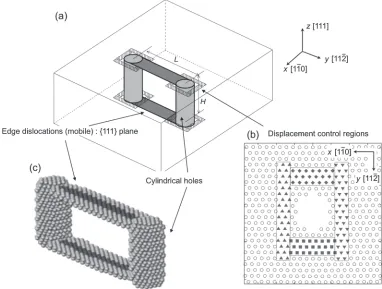
Figure 1 shows our developed FrankRead source model. The embedded atom method for aluminum, proposed by Mishin et al.,23) is adopted for the atomic interactions. The crystal orientation is set to be the same as that used in the model reported by de Koning et al.19) However, it should be noted that the Burgers vectors of the two dislocations created on the{111}planes and the two dislocations created on the{112}planes have directions opposite to those given in the de Koning model because of the different procedures applied to make the FrankRead sources. The FrankRead source in our model is created by introducing an atomic plate into the {110} atomic layers. The dimensions of the atomic plate areLand Hin theyand zdirections, respectively.
We performed a preliminary simulation by applying the
FrankRead source model developed by de Koning using
H=4 nm and L=10 nm. We observed cross slips which
have their stating point at the pinning arms of {112} dislocations, a migration of the pinning points, and the dislocation bow-out from the dislocation segment on the {112} planes before reaching the critical conditions. These results suggest that no perfect dislocation bow-out motion occurred when applying the model by de Koning. This unexpected phenomenon has also been reported by Li
et al.20) and Tsuruet al.11) To obtain strong pinning points,
cylindrical holes with a diameter of 1 nm are introduced by removing the dislocation core structure on the{112}planes. The dislocation segments on the {111} planes are thus terminated by the free surfaces of the cylindrical holes. Weinbergeret al.reported that cylindrical holes have enough dislocation-pinning potential.21) Furthermore, to prevent a cross slip, whose starting point is the pinning segment along the [111] direction, the x-directional displacements of the atomic clusters located next to the slip plane of the dislocation segments on the {111} planes are controlled. The displacement-controlled regions around the cylindrical holes are shown in Fig. 1(a) as hatching regions and in Fig. 1(b) as solid marked atoms. Each FrankRead source corner has four atomic clusters, as shown in Fig. 1(b), and the
x-directional displacement of each cluster is taken from the average x-directional displacement of each atom in that cluster. The other directional displacements of the atomic clusters are not controlled.
The dimensions of the analytical models in the x,yandz
directions (lx, ly and lz) are set to 40, 40 and 20 nm, respectively, and periodic boundary conditions are adopted in all directions. H is set to 4, 6 and 8 nm, and L is set to be greater than or equal toH. Each analytical model is relaxed for 20 ps under no external stress. The analysis temperature is kept at 10 K by the velocity scaling method,24) and each dimensionlx,lyandlzis controlled to keep the nominal stress at zero.25)The equilibrium atomic configuration of the Frank Read source is shown in Fig. 1(c), where the dark- and light-gray spheres correspond to atoms in the local hexagonal close-packed (hcp) configuration and defect structures,
respectively; the atoms in the face-centered cubic structure are not shown. The classification of atomic structures is performed by common neighbor analysis.26)For each relaxed model, shear deformation tests are performed at£_zx¼ 5
108 1=sat 10 K to investigate the dislocation bow-out motion
from the FrankRead source.
3. Results and Discussions
3.1 Dislocation multiplication from the FrankRead source
Figure 2 shows the changes in shape of the upper
dislocation segment with H=L=4 nm under external
loading. The lower dislocation segment behaves similar to the upper one. Figure 3 shows the variations in the number of defect atoms (Ndef), including hcp atoms. The letters in Fig. 3 correspond to the shapes of the dislocation bowing-out segment in Fig. 2. Initially, the value of Ndef increases gradually, until the dislocation bow-out state in Fig. 2(b) is reached, and after that it continues to grow dramatically. Finally, a perfect dislocation loop is formed, as shown in Fig. 2(f ). Because periodic boundary conditions are adopted in all directions, the dislocation loop is eventually destroyed by neighboring dislocation loops in image cells (dislocation annihilation), and therefore, the defect structures in the analytical model return to their initial state with plastic deformation of one of the Burgers vectors. As shown in Fig. 3, the dislocation segment can regenerate a dislocation loop under an external loading, which confirms that our developed FrankRead source has strong pinning points for
[image:2.595.106.488.72.361.2]the dislocation segments and can suppress the cross slips. Thus, our results demonstrate that dislocation multiplication can be realized by atomic simulations.
3.2 Critical dislocation bow-out configuration
In situation (b) in Fig. 3,Ndefincreases dramatically once the critical conditions for the dislocation bow-out motion are reached. The stress in situation (b) can therefore be attributed to the critical shear stress,¸MD.27)Figure 4 shows the shapes of dislocation segments with differentLvalues in the critical state. The value of H is fixed to 4 nm in all models. The white broken lines in Fig. 4 represent the critical dislocation configuration in an isotropic elastic body, with a Poisson ratio of 0.33, estimated by de Witet al.28)Because of the different line tensions between the edge and screw dislocation components, the critical configuration does not show a perfect circular form, as estimated by the constant line tension model, but rather an oval shape with a ratio of the minor axis length to the major axis length of 1¹¯, where¯ is the Poisson ratio. The critical configuration obtained by atomic simulations agrees well with the results reported by de Wit et al.because the anisotropic factor, calculated by c44/
(c11¹c12), is 1.25 for aluminum (expressed by the atomic potential); hence, we can assume that this metal shows isotropic elastic properties. Hatanoet al.29)also reported the
same agreement: critical dislocation bow-out shapes, that ends are pinned by nanovoids, in copper calculated by atomic simulations agree well with the results reported by de Wit
et al. The obtained results suggest that the influence of the displacement control regions on the dislocation bow-out motion is neglected in our models.
[image:3.595.91.508.74.211.2]3.3 Critical shear stress for dislocation bow-out
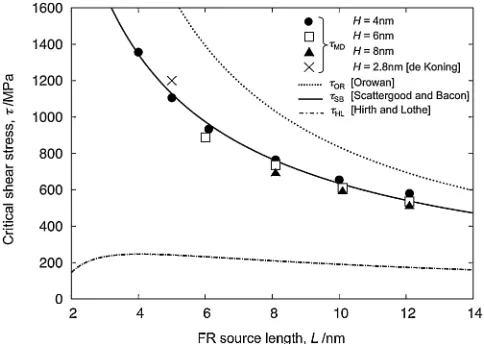
Figure 5 shows the relationship between the critical shear stress ¸MD and the length of the dislocation segment L.
The value of ¸MD reported by de Koning et al. (with
L=5 nm and H=2.8 nm) is also plotted. We also show
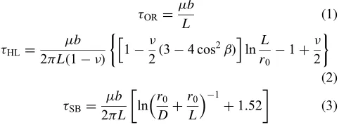
three critical shear stresses, namely,¸OR,¸HL, and¸SB, where ¸OR is estimated by a constant line tension approximation commonly known as the Orowan stress30) [eq. (1)], ¸
HL is derived from analytical expressions for the energies of the dislocation segments with a semi-regular hexagon confi g-uration [eq. (2) by Hirth and Lothe13)], and¸
SBrepresents the void-row bypassing stress, void spacing L, and diameterD, and is numerically evaluated by considering a dislocation self-interaction and a dislocation-void interaction in eq. (3) by Scattergood and Bacon.22)
¸OR ¼®bL ð1Þ
¸HL¼2³L®bð1¯Þ 12¯ð34 cos2¢Þ
h i
lnL r0 1þ
¯ 2
ð2Þ
¸SB¼2³L®b ln rD0þrL0
1
þ1:52
ð3Þ
Here,®,b,r0and¢are the shear modulus, the magnitude of the Burgers vector, the dislocation core radius, and the angle between the Burgers vector and the original dislocation straight line, respectively. In this study,r0 and¢are set tob and 0, respectively, and because eqs. (1) to (3) are valid for isotropic elastic bodies, the shear modulus ® and Poisson’s ratio ¯ are estimated by the Voigt approximation31) for anisotropic elastic bodies, expressed by the atomic potential. We thereby obtain ®=29.2 GPa and ¯=0.33. In eq. (3), althoughDoriginally expresses the void diameter, we assume
that D is ly¹L because the FrankRead sources are
periodically arranged in theydirection in Fig. 1.
Generally, considering the dislocation self-interaction decreases the critical bow-out stress, that is, ¸HL and ¸SB is smaller than¸OR, as shown in Fig. 5. Moreover,¸HLshows a
Fig. 2 Dislocation multiplication from the FrankRead source under external loading in the atomic simulations.L=H=4 nm.
[image:3.595.55.285.250.414.2] [image:3.595.309.550.518.607.2]non-monotonic dependence on L, as shown in Fig. 5. The dislocation bow-out from the FrankRead source with this non-monotonic dependence is expected to be a dominant mechanism for explaining the inverse HallPetch relation found for a number of nanocrystalline metals.32) However,
the ¸MD value obtained by atomic simulations shows a
monotonic dependence on L, which means that ¸MD
continuously increases with decreasing L. It is interesting that the¸MDvalues obtained by our atomic modelsfit the¸SB values obtained by continuum model simulations, which include several approximations regarding the dislocation core radius used (r0=b) and the dislocation-void interaction considered using reasonable surface energy.22)Osetskyet al. also found the same agreement for the motion of an infinite, straight butflexible edge dislocation through a row of voids with diameters ranging between 0.9 and 4 nm in body-centered cubic iron.33) These results suggest that the continuum model based on elasticity theory has enough potential to describe dislocation bow-out motions, even in the nanometer region. Our atomic simulations studies also show that it is difficult to explain the inverse HallPetch relation by using the dislocation bow-out motion from the FrankRead source.
3.4 Influence of dislocationdislocation interactions on the dislocation bow-out
As shown in Fig. 5, the¸MDvalues, including the results of the pinning arms of the {112} dislocations reported by de Koning et al.,19) decreases with increasing H, which is the distance between the upper and lower dislocation segments
in the absence of external loading. If we assume that the influences of the pinning points of both the cylindrical holes and the{112}dislocations on the dislocation bow-out motion are similar, the interactions between the upper and lower dislocations will influence the value of ¸MD. Foreman suggests that the critical bow-out stress for an edge dislocation segment is approximately described by:
¸c¼A2³L®b ln rL 0
þB
; ð4Þ
where A is almost 1 for the edge and 1.5 for the screw segments, and the constant Bdepends on the orientation of the side-arms and the presence of local stressfields.14)In this section, we assume that ¸MD is expressed by eq. (4) and evaluate the influence of dislocationdislocation elastic interactions by comparing the critical stress ¸FO obtained by Foreman14) for a dislocation segment L with vertical dislocation arms to the glide plane of the segment using the Brown self-stress method.15)Figure 6 shows the relationship between the critical shear stress ¸MD(in units of®b/L:¸OR) and L/r0 (r0=b). The broken and solid lines represent¸FO and eq. (4), respectively. The values of the constant B,
fitted to eachHvalue, are also shown in Fig. 6. Although the upper and lower dislocation segments in the atomic models interact with other dislocation segments in the image cells (owing to periodic boundary conditions), the relationship between ¸MD/¸OR and L/r0 is found tofit the form eq. (4), withA=1, for all the studiedHvalues. A similar influence of the periodic boundary conditions is observed in discrete dislocation simulations.18)
Fig. 5 Critical shear stress as a function of the FrankRead source length. Fig. 6 Critical shear stress (in units of®b/L) as a function of the Frank Read source length (in units ofr0).
[image:4.595.103.496.73.156.2] [image:4.595.48.290.208.380.2] [image:4.595.303.550.210.379.2]by the broken line. This relationship is expressed by the equation B=2.6/H+0.66; however, it is not easy to analytically understand. The critical shear stress ¸MD for dislocation multiplication from the FrankRead source in atomic models is described by a form of eq. (4), and the
value of ¸MD when H¼ ¨ is possibly expressed by ¸FO
assuming that the influences of the pinning points of the cylindrical holes and dislocations on the dislocation bow-out motion are similar.
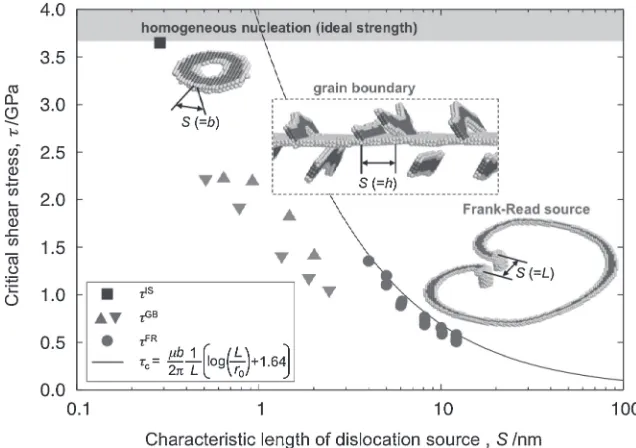
for dislocation nucleation from structural units in the tilt grain boundaries.7)The ideal shear strength,¸IS, is estimated using the critical shear stress for homogeneous nucleation of dislocation loops in a perfect crystal structure whose crystal orientation is the same as that used in the FrankRead source simulation. All the critical shear stresses are evaluated using the (111)[110] shear stress component. The analysis temper-ature is maintained at 10 K for all the simulations, and the strain rates are£_ ¼5108 1=sand¾_¼1109 1=sfor the homogeneous dislocation nucleation model and the grain boundary model, respectively. The obtained ideal shear strength, ¸IS, evaluated by the homogeneous nucleation of dislocation loops, is 3.65 GPa.
[image:5.595.52.284.288.451.2]We introduce a characteristic length of the dislocation sources S to compare the critical shear stresses for various dislocation sources.S is determined by the source lengthL, regular intervals of the structural units h,7) and Burgers vectors b for the FrankRead source, the grain boundary dislocation source, and the homogeneous dislocation nucle-ation source, respectively. It should be noted that S has no connection with grain size, except for the FrankRead source. Figure 8 shows the relationship between the critical shear stress and S for each dislocation source. ¸FR continuously increases with decreasing lengthS. The solid line obtained by
a continuum model in eq. (4) (with A=1 and B=1.64)
indicates that ¸FR becomes larger than ¸IS if S is smaller
than 1 nm. However, we performed a FrankRead source
simulation using S=3 nm and H=4 nm in the atomic
Fig. 7 ConstantBin eq. (4) as a function ofH¹1. The symbols , , and©have the same meaning as in Fig. 6, and represents the results obtained by Foreman14)whenH¼ ¨.
Fig. 8 Relationship between critical shear stress and characteristic length of the dislocation source. The symbols , ( ) and represent the critical shear stresses¸FR(=¸MD),¸GBunder tensile loading (compressive loading), and¸IS, respectively. Grain boundary structures, in descending order by regular intervals of structural unitsS(=h), are73,77,15 and59 for tensile loading, and105,
[image:5.595.137.455.516.740.2]model; we observed that dislocation multiplication occurred (¸FRµ1.81.9 GPa), but the critical configuration of the dislocation bow-out was different from that shown in Fig. 4. This is due to the interaction between the bowing-out dislocation and another dislocation nucleation from the cylindrical hole, which is observed when¸reaches 1.7 GPa. Furthermore, in the case ofS=2 nm andH=4 nm, an edge dislocation dipole terminated by cylindrical holes, as shown in Fig. 1(c), cannot be constructed after relaxation because of the short distance between the two surfaces of the cylindrical holes (i.e., approximately 1 nm). Therefore, the minimum length ofSis 4 nm for our developed FrankRead source, and the maximum ¸FRvalue is 1.36 GPa.
In the case of the grain boundary dislocation source, ¸GB increases upon decreasing the regular interval of structural units S. Because edge dislocations are nucleated from the structural units, the elastic interactions between grain boundary dislocations existing at the structural unit7)strongly influence ¸GB. The minimum ¸GB value is approximately 1 GPa in the case of 105 under compressive loading; this value is smaller than that of ¸FR for S=5 nm. However, almost all¸GBvalues are larger than the maximum¸FRvalue, which suggests that the dominant dislocation source is the FrankRead source if a crystal contains FrankRead sources
with a source length S larger than approximately 5 nm.
However, it should be noted that there is a possibility of decreasing the value of¸GB, obtained by atomic simulations using bicrystal models under nearly athermal condition,7) if we consider the thermally activated process under a reasonable strain rate used in conventional experiments and stress concentration at grain boundaries and triple junctions.
4. Conclusion
Dislocation multiplication from the FrankRead source is realized by atomic models. The obtained critical shape and stress for the dislocation bow-out motion are compared with previously reported results to evaluate them. Our main
findings are summarized as follows:
(1) Dislocation multiplication from the FrankRead source is realized by atomic models by adopting cylindrical holes as a strong pinning point to the dislocation-bowing segment and also suppressing cross slips, which have their starting point at the surface of the pinning holes.
(2) The critical configuration for the dislocation bow-out obtained by atomic simulations exhibits an oval shape with a ratio 1¹¯ between the minor and major axis lengths. The obtained shape agrees well with the results obtained by the line tension model.
(3) The critical shear stress for the dislocation bow-out, determined by atomic models, is found to continuously increase with decreasing values of the FrankRead source length L. This can be expressed by the function L¹1lnL, which is obtained by a continuum model based on elasticity theory, even at the nanometer scale.
(4) The minimum FrankRead source lengthLrealized in the developed atomic model is 4 nm and the maximum critical shear stress, which is one third of the ideal shear strength, is larger than that for dislocation nucleation from
h112i tilt grain boundaries with long structural periodicities.
Acknowledgements
This research was supported by the Ministry of Education,
Culture, Sports, Science and Technology (MEXT)
KAKENHI Grant Number 22102007, the Japan Science and Technology Agency (JST) under Collaborative Research
Based on Industrial Demand “Heterogeneous Structure
Control: Towards Innovative Development of Metallic
Structural Materials”, and the Japan Society for the
Promotion of Science (JSPS) KAKENHI Grant Number 24560091.
REFERENCES
1) E. O. Hall:Proc. Phys. Soc. B64(1951) 747753. 2) N. J. Petch: J. Iron Steel Inst.174(1953) 2528.
3) J. C. M. Li and Y. T. Chou: Metall. Trans.1(1970) 11451159. 4) N. Kamikawa, X. Huang, N. Tsuji and N. Hansen:Acta Mater. 57
(2009) 41984208.
5) D. E. Spearot, M. A. Tschopp, K. I. Jacob and D. L. McDowell:Acta Mater.55(2007) 705714.
6) M. Kato:Mater. Sci. Eng. A516(2009) 276282. 7) T. Shimokawa:Phys. Rev. B82(2010) 174122.
8) Y. Estrin, H. S. Kim and F. R. N. Nabarro:Acta Mater.55(2007) 6401 6407.
9) T. Shimokawa, T. Kinari and S. Shintaku: Phys. Rev. B 75(2007) 144108.
10) T. Shimokawa, M. Tanaka, K. Kinoshita and K. Higashida:Phys. Rev. B83(2011) 214113.
11) T. Tsuru, Y. Aoyagi, Y. Kaji and T. Shimokawa:Mater. Trans. 54
(2013) 15801586.
12) F. C. Frank and W. T. Read, Jr.:Phys. Rev.79(1950) 722723. 13) J. P. Hirth and J. Lothe:Theory of Dislocations, 2nd ed., (McGraw-Hill,
New York, 1982) p. 752.
14) A. J. E. Foreman:Philos. Mag.15(1967) 10111021. 15) L. M. Brown:Philos. Mag.10(1964) 441466.
16) D. Gomez-Garcia, B. Devincre and L. Kubin:J. Comput. Aided Mater. Des.6(1999) 157164.
17) T. Ohashi, M. Kawamukai and H. Zbib:Int. J. Plasticity23(2007) 897 914.
18) S. Soleymani Shishvan, S. Mohammadi and M. Rahimian: Model. Simul. Mater. Sci. Eng.16(2008) 075002.
19) M. de Koning, W. Cai and V. V. Bulatov:Phys. Rev. Lett.91(2003) 025503.
20) X. Y. Li and W. Yang: Phys. Rev. B74(2006) 144108.
21) C. R. Weinberger and G. J. Tucker: Model. Simul. Mater. Sci. Eng.20
(2012) 075001.
22) R. O. Scattergood and D. J. Bacon:Acta Metall.30(1982) 16651677. 23) Y. Mishin, D. Farkas, M. J. Mehl and D. A. Papaconstantopoulos:Phys.
Rev. B59(1999) 33933407.
24) M. P. Allen and D. J. Tildesley: Computer Simulation of Liquids, (Oxford University Press, New York, 1987).
25) M. Parrinello and A. Rahman:Phys. Rev. Lett.45(1980) 11961199. 26) J. Dana Honeycutt and H. C. Andersen:J. Phys. Chem. 91(1987)
49504963.
27) To estimate the critical state of dislocation bow-out correctly, we also use values of dNdef/dt.
28) G. de Wit and J. S. Koehler:Phys. Rev.116(1959) 11131120. 29) T. Hatano and H. Matsui:Phys. Rev. B72(2005) 094105.
30) D. Hull and D. J. Bacon: Introduction to Dislocations, fourth ed., (Butterworth Heinemann, 2001) p. 150.
31) W. Voigt:Lehrbuch der Kristallphysik, (Teubner, Leipzig, 1928). 32) J. Lian, B. Baudelet and A. A. Nazarov:Mater. Sci. Eng. A172(1993)
2329.