Topcon Link
Reference Manual
Part Number 7040-0026 Rev B
©Copyright Topcon Positioning Systems, Inc. May, 2003
All contents in this manual are copyrighted by Topcon Positioning System, Inc. All rights reserved.
The information contained herein may not be used, accessed, copied, stored, displayed, sold, modified, published, or distributed, or otherwise reproduced without express written
i
T
able of Contents
Preface ... v
Terms and Conditions... v Manual Conventions... ix Chapter 1
Introduction ... 1-1
Installing Topcon Link ... 1-2 Starting Topcon Link ... 1-5 Getting Acquainted ... 1-5 Main Window ... 1-5 Menu Bar ... 1-6 File Menu ... 1-6 Edit Menu ... 1-7 View Menu ... 1-7 Process Menu ... 1-8 Window Menu ... 1-8 Help Menu ... 1-8 Toolbar ... 1-9 Chapter 2
Transferring Files ... 2-1
Importing Files ... 2-1 Adding Devices ... 2-3 Importing TPS Receiver Files ... 2-4 Set Communication Parameters ... 2-4 Select Files to Import ... 2-5 Importing TPS Controller Files ... 2-6ii
Import TPS Controller Files ... 2-11 Importing Total Station Files ... 2-12 Exporting Files ... 2-15 Exporting Files to Total Stations ... 2-16 Exporting Files to TPS Controllers ... 2-18 Chapter 3
Converting Files ... 3-1
Converting Coordinate Files ... 3-6 ASCII/TSV and Custom Text Format Parameters 3-8 Name,Lat,Lon,H,Code Format Parameters ... 3-9 Other Coordinate File Types Format Parameters 3-9 Converting TopSURV Files ... 3-10 Converting Total Station Raw Data Files ... 3-11 Converting Topcon XML Files ... 3-14 Converting GPS+ Raw Data Files ... 3-16 Converting to GIS Files ... 3-16 Converting to TPD GPS+ Raw Data Files ... 3-19 Converting to RINEX GPS+ Raw Data Files ... 3-19 Chapter 4
Maintaining Files ... 4-1
Opening Files ... 4-1 Creating User-defined File Formats ... 4-3 Viewing Files ... 4-5 Coordinate File Data Table ... 4-5 Total Station Raw Data File Data Table ... 4-7 TopSURV File Data Table ... 4-10 Viewing File Properties ... 4-16 Editing Files ... 4-17 Saving Files ... 4-17 Save Changes to Current File and Format .... 4-17 Save Changes to a Different Format ... 4-18 Save Changes to a Different File ... 4-19 Editing Coordinate Files ... 4-20
Table of Contents
iii
Edit Name and Note Properties ... 4-21Edit Coordinate Properties ... 4-21 Edit CAD Properties ... 4-23 Editing Total Station Raw Data Files ... 4-23
Edit Name, Instrument Height, and Number Properties ... 4-25 Edit Point To and Notes Properties ... 4-26 Edit Reflector Height and Azimuth Properties 4-26 Edit Offset Properties ... 4-27 Edit CAD Properties ... 4-28 Edit String Properties ... 4-28 Edit Observation Display Properties ... 4-29 Edit Point Code Description ... 4-30 Edit Multiple Points ... 4-31 Editing TopSURV Files ... 4-31 Edit Point Name and Note Properties ... 4-33 Edit Point Coordinates ... 4-33 Add New Point Code ... 4-34 Edit GPS Occupation Point Name ... 4-35 Edit GPS Occupation Antenna Parameters .. 4-36 Edit GPS Occupation Offsets ... 4-36 Edit TS Obs Parameters ... 4-37 Edit GPS Obs Point Notes ... 4-37 View GPS Obs Point Observations ... 4-38 Edit GPS Observation Display ... 4-38 Edit TopSURV File Codes ... 4-39 Chapter 5
Using Files ... 5-1
Computing Coordinates ... 5-1 Traverse Adjustment ... 5-2 Least Squares Method ... 5-4 Compass Rule ... 5-4 Transit Rule ... 5-5
iv
Interior Angle Balancing Method ... 5-6 Azimuth Balancing Method ... 5-6 User-defined Parameters ... 5-6 Printing Files ... 5-10 Appendix A
Cables/COM Ports ... A-1
Serial Interface Cable ... A-1 Parallel Interface Cable ... A-2 Serial C-RS232C Connector Definition ... A-3 Total Station COM Port Settings ... A-4 GNSS Receiver COM Port Settings ... A-7 Appendix B
Sample File Formats ... B-1
Coordinate File Formats ... B-1 GTS-6 Points Coordinate Format ... B-1 GTS-7 Points Coordinate Format ... B-2 Name,E,N,Z,Code Coordinate Format ... B-3 Name,Lat,Lon,Ht,Code Coordinate Format ... B-3 Name,N,E,Z,Code Coordinate Format ... B-4 Raw Data File Formats ... B-5 GTS-6 Raw Format ... B-5 GTS-7 Raw Format ... B-6 GTS-7+ Raw Format ... B-9 TOPCON XML File Format ... B-10 DXF Format ... B-12 Printed File Formats ... B-15
v
P
reface
Thank you for purchasing your Topcon receiver, survey product or accessory (the “Product”). The materials available in this manual (the “Manual”) have been prepared by Topcon Positioning Systems, Inc. (“TPS”) for owners of Topcon products. This Manual is designed to assist owners with the use of software (the “Software”) to be used with the Product and its use is subject to these terms and conditions (the “Terms and Conditions”).
NOTICE
Please read these Terms and Conditions
carefully.
Terms and Conditions
PROFESSIONAL USE – Topcon Products are designed to be used by a professional. The user is required to be a professional surveyor or have a good knowledge of surveying, in order to understand the user and safety instructions before operating, inspecting or adjusting. Always wear required safety attire (safety shoes, hard hat, etc.) when operating the Products. COPYRIGHT – All information contained in this Manual is the intellectual property of, and copyrighted material of TPS. All rights are reserved. You may not use, access, copy, store, display, create derivative works of, sell, modify, publish, distribute, or allow any third party access to, any graphics, content,
vi
expenditure of considerable work, time and money, and are the result of original selection, coordination and arrangement by TPS.
TRADEMARKS – Topcon®, Topcon Link™, TopSURV™, and Topcon Positioning Systems™ are trademarks of TPS.
Windows® and ActiveSync® are registered trademarks of Microsoft Corporation. Product and company names mentioned herein may be trademarks of their respective owners.
DISCLAIMER OF WARRANTY – EXCEPT FOR ANY WARRANTIES IN APPENDIX E OR A WARRANTY CARD ACCOMPANYING THE PRODUCT, THIS MANUAL, THE PRODUCT, AND ANY ACCOMPANYING SOFTWARE ARE PROVIDED “AS-IS.” THERE ARE NO OTHER
WARRANTIES. TPS DISCLAIMS ANY IMPLIED
WARRANTY OF MERCHANTABILITY OR FITNESS FOR ANY PARTICULAR USE OR PURPOSE. TPS AND ITS DISTRIBUTORS SHALL NOT BE LIABLE FOR
TECHNICAL OR EDITORIAL ERRORS OR OMISSIONS CONTAINED HEREIN; NOR FOR INCIDENTAL OR CONSEQUENTIAL DAMAGES RESULTING FROM THE FURNISHING, PERFORMANCE OR USE OF THIS
MATERIAL, THE SOFTWARE, OR THE PRODUCT. SUCH DISCLAIMED DAMAGES INCLUDE, BUT ARE NOT LIMITED TO, LOSS OF TIME, LOSS OR DESTRUCTION OF DATA, LOSS OF PROFIT, SAVINGS OR REVENUE, OR LOSS OF THE PRODUCT’S USE. IN ADDITION, TPS IS NOT RESPONSIBLE OR LIABLE FOR DAMAGES OR COSTS INCURRED IN CONNECTION WITH OBTAINING SUBSTITUTE PRODUCTS OR SOFTWARE, CLAIMS BY OTHERS, INCONVENIENCE, OR ANY OTHER COSTS. IN ANY EVENT, TPS SHALL HAVE NO LIABILITY FOR
vii
DAMAGES OR OTHERWISE TO YOU OR ANY OTHERPERSON OR ENTITY IN EXCESS OF THE PURCHASE PRICE FOR THE PORDUCT.
LICENSE AGREEMENT – Use of the Software and any other computer programs or software supplied by TPS or downloaded from a TPS website (the “Software”) to be used with a Topcon Product constitutes acceptance of these Terms and Conditions in this Manual and an agreement to abide by these Terms and Conditions. The user is granted a personal, exclusive, non-transferable license to use such Software under the terms stated herein and in any case only with a single Product or single computer. You may make one (1) backup copy of the Software. Otherwise, the Software may not be copied or reproduced. You may not assign or transfer the Software or this license without the express written consent of TPS. This license is effective until terminated. You may terminate the license at any time by destroying the Software and Manual. TPS may terminate the license if you fail to comply with any of the Terms or Conditions. You agree to destroy the Software and manual upon termination of your use of the Product. All ownership, copyright and other intellectual property rights in and to the Software belong to TPS. If these license terms are not acceptable, return any unused Software and the Manual.
CONFIDENTIALITY – This Manual, its contents and the Software (collectively, the “Confidential Information”) are the confidential and proprietary information of TPS. You agree to treat TPS’ Confidential Information with a degree of care no less stringent than the degree of care you would use in safeguarding your own most valuable trade secrets. Nothing in this paragraph shall restrict you from disclosing Confidential Information to your employees as may be necessary or appropriate to operate or care for the Product. Such employees must also keep the Confidentiality
viii
order or other appropriate remedy.
WEBSITE; OTHER STATEMENTS – No statement contained at the TPS website (or any other website) or in any other
advertisements or TPS literature or made by an employee or independent contractor of TPS modifies these Terms and Conditions (including the Software License Agreement, Disclaimer of Warranty and limitation of liability).
SAFETY – Improper use of a Topcon Product can lead to injury to persons or property and/or malfunction of the Product. The Product should only be repaired by authorized TPS warranty service centers. Users should review and heed the safety warnings in the manual accompanying the Product.
MISCELLANEOUS – The above Terms and Conditions may be amended, modified, superseded, or canceled, at any time by TPS. The above Terms and Conditions will be governed by, and construed in accordance with, the laws of the State of California, without reference to conflict of laws.
ix
Manual Conventions
This manual uses the following conventions: Example Explanation
File->Exit Click the File menu and click Exit. Enter Indicates the button or key labeled Enter. Topo Indicates the name of a dialog box or screen.
Notes Indicates a field on a dialog box or screen, or a tab within a dialog box or screen.
TIP
Supplementary information that can help you
configure, maintain, or set up a system.
NOTICE
Supplementary information that can have an
affect on system operation, system
performance, measurements, personal safety.
CAUTION
Notification that an action has the potential
to adversely affect system operation,
system performance, data integrity, or
personal health.
Notes:
Chapter 1
1-1
I
ntroduction
Topcon Link™ can be used to:
• Import files from Topcon Conventional Total Stations, Robotic Total Stations, a TPS Controller, and TPS GPS+ receivers to a computer.
• View and edit coordinate and raw data files.
• Reorganize coordinate and raw data files to files of the following formats:
• Create (make ready) and export coordinate files from a computer to a TPS Controller and/or a Total Station.
Table 1-1. Topcon Link File Formats
–TopSURV –DXF –Shape
–Topcon TS Raw formats (GTS-6, GTS-7, GTS-7+, FC-5,
GTS-210/310)
–Topcon TS Coordinate formats (GTS-7, FC-5, GTS-210/310-10, GTS-210/310-12)
–Char-delimited Coordinate formats (Name,Lat,Lon,Ht,Code;
Name,N,E,Z,Code; Name,E,N,Z,Code; Custom) –TSV ASCII Coordinate format –RINEX
–TPS receiver data format (TPD) –Topcon XML
1-2
Installing Topcon Link
Topcon Link software comes on a CD to install on a computer. 1. Insert the Topcon Link CD into the CD-ROM drive. The
InstallShield® Wizard starts up.
2. Click Next on Topcon Link install Wizard dialog box to start the installation process.
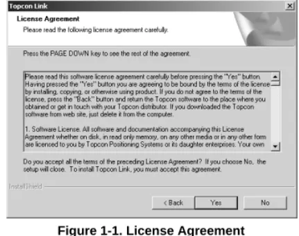
3. Press Yes on the License Agreement dialog box (Figure 1-1). Clicking No terminates the installation.
Figure 1-1. License Agreement
4. On the Customer Information dialog box, enter the User and Company names, then click Next (Figure 1-2).
Installing Topcon Link
1-3
5. On the Choose Destination Location dialog box, clickBrowse to select the folder or type a new folder name in which to install the Topcon Link. Click Next (Figure 1-3).
Figure 1-3. Choose Destination Location
6. On the Setup Type dialog box, select the desired type of setup (usually Typical) (Figure 1-4). Then click Next.
1-4
7. On the Select Program Folder dialog box, select a current folder or type a new program folder name for Topcon Link (Figure 1-5). Then click Next.
Figure 1-5. Select Program Folder
The installation process starts.
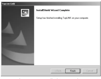
8. Click Finish to exit the installation (Figure 1-6).
Figure 1-6. Installation Complete
9. Create a Topcon Link shortcut (Figure 1-7) on the computer desktop from which to quickly start the program.
Starting Topcon Link
1-5
Starting Topcon Link
To start Topcon Link, do one of the following:
• Click Start->Programs->Topcon->Topcon Link. • Double-click the Topcon Link desktop shortcut.
The Topcon Link main window displays (see “Main Window” on page 1-5 and Figure 1-8 on page 1-6).
Getting Acquainted
This section introduces the various functions available in Topcon Link for viewing, configuring, or editing data files.
Main Window
The main window (Figure 1-8 on page 1-6) has the following components:
• Header – contains path information for job files. • System buttons – the minimize, maximize, and close
window buttons.
• Menu bar – contains drop-down menus for the various Topcon Tools functions.
• Toolbar – contains shortcut buttons to frequently used options.
• Work area – the area within which dialog boxes, job file information, and pop-up menus display.
• Status bar – displays informative messages about Topcon Tools and various files.
• File information – when a job file opens, displays applicable linear unit, angular unit, type of coordinate system, and coordinate system information.
1-6
Figure 1-8. Main Window Components
Menu Bar
The menu bar provides access to most options available using Topcon Tools in six, clickable drop-down menus.
File Menu
The File menu (Figure 1-9 on page 1-7): • opens, saves, and closes a file; • imports and exports data;
• converts a file from one format to another; • prints information from an active file; • displays job file configuration parameters; • displays recently accessed files.
Menu Bar Toolbar Work Area Status Bar System Buttons Header File Information
Getting Acquainted
1-7
Figure 1-9. File MenuEdit Menu
The Edit menu (Figure 1-10):
• allows a redo or undo of the last operation, or discards all changes;
• cuts, copies, pastes, or deletes information.
Figure 1-10. Edit Menu
View Menu
The View menu (Figure 1-11) provides access to viewing and hiding the Toolbar and Status bar.
1-8
Process Menu
The Process menu (Figure 1-12): • computes coordinate; • sets processing properties.
Figure 1-12. Process Menu
Window Menu
The Window menu (Figure 1-13):
• closes the current or all open windows;
• arranges open windows in a cascade (stacked) or tile (adjacent) views;
• arranges icons;
• indicates the current window.
Figure 1-13. Window Menu
Help Menu
The Help menu (Figure 1-14):
• provides context sensitive help and a help file; • gives Topcon Link version and build date
information.
Getting Acquainted
1-9
ToolbarThe Toolbar for Topcon Link (Figure 1-15) contains buttons for frequently used functions.
Figure 1-15. Toolbar
Upon startup, the Toolbar displays beneath the menu bar. • To display or hide the Toolbar, click View->Toolbar. A
check mark indicates the Toolbar is visible.
• To move the Toolbar menu, click the bar to the left of the Open icon, then drag the Toolbar to a new location and release the mouse button.
Table 1-2 lists and describes the various Toolbar icons. Table 1-2. Toolbar Icon Functions
Icon Description
Open – Opens a file.
1. Click the button to display the Open dialog box.
2. Select the name of file and/or select a path or folder on the hard disk drive, local area network, or store media.
3. Click Open.
Save – Saves files to the current directory.
Import File from Device – Collects the observed files from TPS GPS+ receivers, TPS controller, and Conventional or Robotic Total Stations.
1. Click the button to display the Import file from device dialog box.
2. Select the device and click Next.
See “Importing Files” on page 2-1 for more details.
Export to Device – Exports data from files to a TPS controller or a Conventional or Robotic Total Station.
1. Click the button to display the Export to Device dialog box. 2. Select the device and click Next.
1-10
Convert Files – Displays the Convert File dialog box. See “Converting Files” on page 3-1 for more details.
Cut – Removes the marked area or text from the page, placing it on the Windows® clipboard.
Copy – Copies text from the page, placing it on the Windows clipboard.
Paste – Places selected text on the Windows clipboard. Undo – Reverses the results.
Redo – Returns the results.
Compute Coordinates of Points – Computes (calculates) the coordinates of the points of the current file.
Print – Prints the current window or table.
About Topcon Tools – Displays the About Topcon Tools dialog box.
Table 1-2. Toolbar Icon Functions
Chapter 2
2-1
T
ransferring Files
This chapter describes importing and exporting, or transferring, files between devices and a computer using Topcon Link.
Importing Files
The following sections describe importing data files from a device, such as a Conventional/Robotic Total Station, a TPS GPS+ Receiver, or TPS Controller, to a computer.
1. To import files, do one of the following:
• Click File->Import from Device (Figure 2-1).
Figure 2-1. File->Import From Device
• Press F7.
• Click the Import button on the Toolbar (Figure 2-2).
2-2
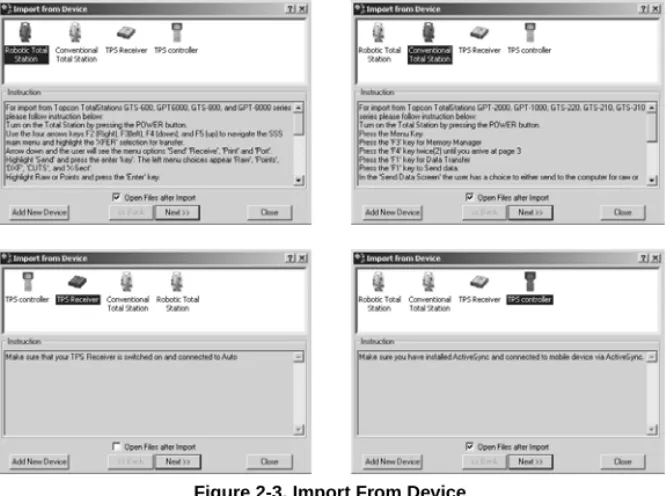
The Import from Device dialog box displays (Figure 2-3). This dialog box consists of two panels.
• The upper panel displays icons of the four types of devices that provide raw data files for importing to Topcon Link. Initially, the previously chosen device is selected.
• The lower panel displays specific instructions for getting a device ready to import files.
Figure 2-3. Import From Device
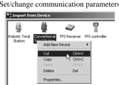
• To open the imported file after completing the Import process, click and enable Open Files After Import. • Right-clicking any device icon displays a pop-up menu
from which you can (Figure 2-4 on page 2-3): –Add a new device.
–Cut, copy, or delete a chosen device. –Change an icon’s image.
Importing Files
2-3
–Set/change communication parameters.Figure 2-4. Device Pop-up Menu
Adding Devices
1. To include a new device to the Import From Device list, right-click within the upper panel, click Add New Device from the pop-menu, then select the desired device type (Figure 2-5).
Figure 2-5. Import From Device – Pop-up Menu
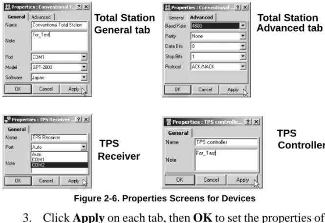
2. On the Properties dialog box, enter the device name, comment, computer port, Total Station model (if applicable), and connection parameters (Figure 2-6 on page 2-4).
2-4
Figure 2-6. Properties Screens for Devices
3. Click Apply on each tab, then OK to set the properties of the new device and close the Properties dialog box. Importing TPS Receiver Files
To import data from a TPS GPS+ receiver, follow the procedure below.
Set Communication Parameters
On the Import from Device dialog box set the correct communication parameters.
1. For the Topcon Link and TPS GPS+ receiver connection, right-click the TPS GPS+ receiver icon. 2. Click Properties on the pop-up menu.
3. Select the computer serial port the receiver is connected to (Figure 2-7 on page 2-5).
Total Station General tab Total Station Advanced tab Controller TPS Receiver TPS
Importing Files
2-5
Figure 2-7. Select COM Port4. Click Apply, then OK to set the information and close the Properties dialog box.
Select Files to Import
5. Click Next on the Import from Device dialog box. 6. In the Open for Convert dialog box, select the
desired file(s) (hold the Shift key to select multiple files) and click Open (Figure 2-8).
Figure 2-8. Select Files
7. In the right panel, navigate to and select, or create, the folder in which to save the files.
8. Click Next. The Status bar displays the import progress (Figure 2-9).
2-6
If the receiver is switched off, or a COM Port was selected incorrectly, the following dialog box displays (Figure 2-10).
Figure 2-10. Cannot Connect Error Message
Click OK, and check the receiver’s connections. Then repeat the process.
Importing TPS Controller Files
To import data from a TPS Controller to Topcon Link, first install Microsoft® ActiveSync® onto the computer. ActiveSync establishes a connection between the computer and a mobile device, such as a TPS Controller. The mobile device must have the Windows CE operating system. ActiveSync is available for free from the Microsoft website (http://www.microsoft.com).
To establish the connection between the computer and TPS Controller, do the following:
1. Using an RS-232 interface cable, connect the TPS Controller to the serial interface port on the computer. 2. Switch on the TPS Controller and computer.
3. Start Microsoft ActiveSync.
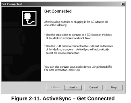
4. Click Next on the Get Connected dialog box (Figure 2-11 on page 2-7).
Importing Files
2-7
Figure 2-11. ActiveSync – Get ConnectedThe computer establishes a connection with the TPS Controller. If the TPS Controller is switched on, and the correct COM Port selected, the following dialog box displays (Figure 2-12).
Figure 2-12. PC and Controller Connected
The system tray also displays a green circle, indicating a successful TPS controller-to-computer connection (Figure 2-13).
Successful Connection
2-8
NOTICE
TPS Controllers keep *.tsv files as database
format files; this format cannot be stored on a
computer. When importing these files from a
TPS Controller to a computer, Topcon Link
converts them to an accessible file format
(*.tlsv) before saving. Topcon Link must be
used to convert the correct *.tlsv files top the
desired format.
CAUTION
To avoid data loss while exporting *.tsv files
from a TPS Controller to a computer, use
only Topcon Link.
Microsoft ActiveSync Settings
If the computer has only one COM Port: 1. Start Microsoft ActiveSync.
2. Click File->Connection Settings (Figure 2-14).
Importing Files
2-9
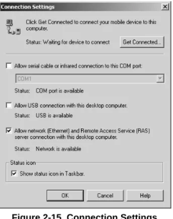
3. On the Connection Settings dialog box, click andenable the following parameters (Figure 2-15): • Allow network (Ethernet) and Remote Access
Service (RAS) server connection with this desktop computer
• Show status icon in Task bar
Figure 2-15. Connection Settings
In this case, ActiveSync does not request the COM Port after disconnecting the TPS Controller from the
computer. The COM Port connects the computer with a TPS GPS+ receiver or Total Station.
If there are two or more COM Ports on the computer: 1. Start Microsoft ActiveSync.
2. Click File->Connection Settings.
3. On the Connection Settings dialog box, set the following parameters (Figure 2-16 on page 2-10): • Click and enable the “Allow serial cable or infrared
2-10
• Select the desired COM port from the drop-down list (usually COM 1)
Figure 2-16. Click Get Connected
In this case Microsoft ActiveSync requests the COM Port after disconnecting the controller and computer. The COM Port is available only for devices that use the Windows CE operating system.
TIP
Use separate COM Ports for
controller connections and
computer-to-receiver/Total Station connections.
When reconnecting the computer and TPS Controller, use the same serial interface port set in the Connection Settings dialog box.
Importing Files
2-11
Import TPS Controller Files
1. Click the Import from Device icon. On the Import from Device dialog box, select the TPS Controller icon and press Next (Figure 2-17).
Figure 2-17. Select TPS Controller
2. On the next Import from Device dialog box, select the desired *.tsv file in the left panel (Figure 2-18).
Figure 2-18. Select Files
3. In the right panel, select a folder in which to save the file. Create a new folder if needed.
4. Press Next. The Status bar displays the import progress (Figure 2-19).
2-12
Importing Total Station Files
The following sections describe importing data files from a Topcon Conventional or Robotic Total Station to a computer. 1. On the Import from Device dialog box, right-click a
Conventional/Robotic Total Station icon and click Properties on the pop-up menu (Figure 2-20).
Figure 2-20. Right-Click Total Station
2. On the Properties dialog box, click the General tab and set the following information (Figure 2-21), then click Apply:
• Select the model of a total station. • Enter any applicable notes.
• Select the computer serial port the Total Station is connected to.
Importing Files
2-13
3. Click Advanced and set the Baud Rate, Data Bits, Parity,Stop Bits, and Protocol (Figure 2-22). Click OK to apply the information and close the dialog box.
Figure 2-22. Properties – Advanced Tab
4. Follow all the steps given in the Instruction panel on the Import from Device dialog box (Figure 2-23) to prepare the Total Station for importing files. Select the file to import.
Figure 2-23. Total Station Instructions – Preparing for Import
5. Click Next on the Import from Device dialog box. The Status bar displays the import progress (Figure 2-24).
2-14
If the data file was successfully imported from the total station to the computer the following window displays (Figure 2-25).
Figure 2-25. Successful Import
6. Click OK.
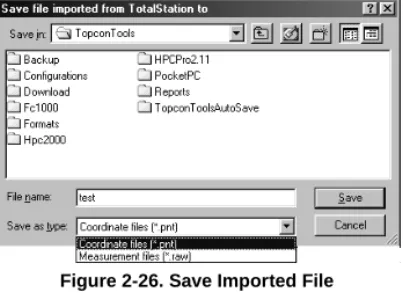
7. On the Save file imported from Total Station to dialog box, define a folder for the file, select the file type and enter a file name (Figure 2-26).
Figure 2-26. Save Imported File
8. Click Save.
If the total station is switched off, not ready for data transfer, or the communication parameters are incorrect, the following window displays (Figure 2-27).
Figure 2-27. Cannot Connect Error Message
Exporting Files
2-15
Exporting Files
The following sections describe exporting coordinate data files from a computer to a device, such as a Total Station, a TPS GPS+ Receiver, or a TPS Controller.
1. To import files, do one of the following:
• Click File->Export to Device (Figure 2-1).
Figure 2-28. File->Export to Device
• Press F8.
• Click the Export button on the Toolbar (Figure 2-2).
Figure 2-29. Export To Device – Toolbar Button
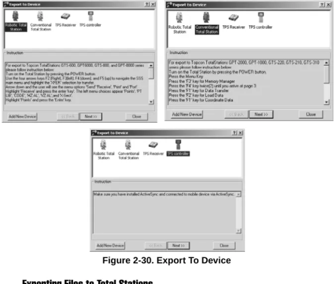
This dialog box consists of two panels (Figure 2-30 on page 2-16):
• The upper panel displays icons of the four types of devices that provide raw data files; however, only the three devices that accept exported data are selectable (TPS Controller, Conventional/Robotic Total Stations). Initially, the previously chosen device is selected.
• The lower panel displays specific instructions for getting a device ready to export files.
2-16
Figure 2-30. Export To Device
Exporting Files to Total Stations
The following procedure describes exporting coordinate files from a computer to any listed model total station.
1. On the Import from Device dialog box, right-click a Conventional/Robotic Total Station icon and click Properties on the pop-up menu (Figure 2-31).
Exporting Files
2-17
2. On the Properties dialog box, click the General tab andset the following information (Figure 2-32), then click Apply:
• Select the model of a total station. • Enter any applicable notes.
• Select the computer serial port the Total Station is connected to.
Figure 2-32. Properties – General Tab
3. Click Advanced and set the Baud Rate, Data Bits, Parity, Stop Bits, and Protocol (Figure 2-33). Click OK to apply the information and close the dialog box.
2-18
4. Follow all the steps given in the Instruction panel on the Export to Device dialog box (Figure 2-34) to prepare the Total Station for exporting files.
Figure 2-34. Total Station Instructions – Preparing for Export
5. Press Next on the Export to Device dialog box.
6. On the Export to Total Station from dialog box, navigate to and select the desired file (Figure 2-35).
Figure 2-35. Export To TotalStation From...
7. Click Open. Check the Total Station for the exported file (refer to the Total Station’s documentation).
Exporting Files to TPS Controllers
To export data from Topcon Link to a TPS Controller, first install and start Microsoft® ActiveSync™ on the computer (see “Importing TPS Controller Files” on page 2-6). A green icon on the system tray indicates a successful connection between the computer and TPS Controller.
Exporting Files
2-19
When exporting files, Topcon Link exports coordinate filesand TopSURV database files from a computer to a TPS Controller.
• When exporting TopSURV database files, Topcon Link converts *.tlsv job format to the *.tsv job format. • When exporting coordinates files, Topcon Link leaves
the files in the current format.
CAUTION
To avoid data loss, use only Topcon Link
when exporting *.tlsv files from a computer
to a TPS Controller.
1. On the Export to Device dialog box, select a TPS Controller and click Next (Figure 2-36).
2-20
2. In the left panel, select the desired coordinate file for export (Figure 2-37).
Figure 2-37. Select File for Export and Folder for File
3. In the right panel, select the TPS Controller folder in which to export the file.
4. Press Next. The Status bar displays the export progress (Figure 2-38).
Chapter 3
3-1
C
onverting Files
Topcon Link™ converts files from: • Coordinate file formats:
–Topcon Total Station (GTS-7, FC-5, GTS-210/310-10, GTS-210/310-12)
–Char-delimited (Name,Lat,Lon,H,Code; Name,N,E,Z,Code; Name,E,N,Z,Code; Custom) –ASCII / TSV
• Measurement file formats from Topcon Total Station raw data formats (GTS-6, GTS-7, GTS-7+, FC-5, GTS-210/310) • TopSURV file format (TopSURV)
• Topcon XML file format (XML) • GPS+ raw measurements file formats
–RINEX
–TPD (Topcon Positioning Data) –TPS / JPS
Topcon Link converts files to: • Any coordinate file to:
–Any other coordinate file –Topcon XML
–TopSURV –DXF
3-2
• Any measurement file to:
–Any other measurement file –Any coordinate file
–DXF –Shape –Topcon XML –TopSURV • TopSURV file to:
–Any coordinate file –Any measurement file –DXF
–Shape –Topcon XML • Topcon XML file to:
–Any coordinate file –Any measurement file –DXF
–Shape –TopSURV • RINEX file to TPD
3-3
1. To convert a file from one format to another, do one of thefollowing:
• Click File->Convert to File (Figure 3-1).
Figure 3-1. File->Convert File.
• Press F5.
• Click Convert File on the Toolbar (Figure 3-2).
Figure 3-2. Convert File – Toolbar Button
The Convert File dialog box displays (Figure 3-3).
Figure 3-3. Convert File Dialog Box
• The left panel displays parameters and values used in the field operations of the file.
• The right panel displays parameters and values necessary after the conversion.
3-4
2. In the left panel, select file type (Figure 3-4).
Figure 3-4. File Format List
3. Click Browse (“...”) and select the file for conversion in the Open for convert dialog box (Figure 3-5).
Figure 3-5. Open for Convert
4. Click Open. The path of the source file displays in the
Source field (Figure 3-6).
Figure 3-6. Convert File – Source
3-5
6. Click Browse (“...”) and select or create a folder in the Selecta file dialog box, then select the destination file type and enter the destination file name. Click Select (Figure 3-7).
Figure 3-7. Select A File
7. Click Advanced Options to display further conversion parameters. Enter the desired information (Figure 3-8).
Figure 3-8. Convert File – Advanced Options
8. Click Convert in the Convert File dialog box to start the file conversion (Figure 3-8).
The following operations depend on the format type of the source and destination files. See the following sections for specific conversion parameters and information.
3-6
Converting Coordinate Files
If converting a coordinate type file, specify the following parameters in the left/right panels:
• The file format (Figure 3-9).
Figure 3-9. Coordinate File Formats
• In the left panel, enable Orthometric Height when the file uses orthometric heights (Figure 3-10).
Figure 3-10. Orthometric Height Checkbox
• In the left panel, enable Fixed to fix the coordinates of points when converting the file to a *.tlsv file (Figure 3-11).
Figure 3-11. Fixed Checkbox
• In the right panel, enable Orthometric Height to calculate orthometric heights for the converted points (Figure 3-12).
Figure 3-12. Orthometric Height
• In the right panel, set the Geoid model: 1. Click Geoids List (Figure 3-13).
Converting Coordinate Files
3-7
2. On the Geoids List dialog box, click Add(Figure 3-14).
Figure 3-14. Geoids List Dialog Box
3. Select the desired *.bin file in Open dialog box and click Open (Figure 3-15).
Figure 3-15. Open window
4. Click Close (Figure 3-16).
Figure 3-16. Geoids List
• In the right panel, select a geoid model (Figure 3-17).
3-8
ASCII/TSV and Custom Text Format Parameters
For ASCII/TSV or Custom Text formats, specify:
• A projection name for the coordinate type (Figure 3-18).
Figure 3-18. Projection List
• Or a Datum for Lat,Lon,H coordinate type (Figure 3-19).
Figure 3-19. Datum List
• Linear units (Figure 3-20).
Converting Coordinate Files
3-9
Name,Lat,Lon,H,Code Format ParametersFor Name,Lat,Lon,H,Code formats, specify the following parameters:
• Datum (Figure 3-21)
Figure 3-21. Datum List
• Linear units (Figure 3-22)
Figure 3-22. Linear Unit List
Other Coordinate File Types Format Parameters
For GTS-7 Points, FC-5, GTS-210/310-10, GTS-210/310-12, Name,E,N,Z,Code or Name,N,E,Z,Code formats, specify the following parameters:
• Projection (Figure 3-23).
Figure 3-23. Projection List
3-10
• For GTS-7 Points, FC-5, GTS-210/310-10 and GTS-210/ 310-12, set the relation between Grid and Ground coordinates.
1. Click the Grid to Ground Parameters button (Figure 3-25).
Figure 3-25. Grid to Ground Parameters Button
2. Enter the applicable transformation parameters (Figure 3-26).
Figure 3-26. Grid to Ground Parameters
3. Click OK.
Converting TopSURV Files
If converting a TopSURV file, select the correct file format (Figure 3-27) and click Convert.
Converting Total Station Raw Data Files
3-11
Converting Total Station Raw Data Files
If converting a Total Station (TS) measurement file, specify the following parameters in the left/right panels.
In the left panel,
• the File format (Figure 3-28).
Figure 3-28. File Format List
• the Projection type (Figure 3-29).
Figure 3-29. Projection List
• the relation between the Grid and Ground coordinates: 1. Click the Grid to Ground coordinates button
(Figure 3-30).
Figure 3-30. Grid to Ground Coordinates Button
2. On the Grid->Ground Parameters dialog box, enter the transformation parameters (Figure 3-31 on page 3-12).
3-12
Figure 3-31. Grid->Ground Parameters Dialog Box
• the order of the coordinates (Figure 3-32).
Figure 3-32. Coordinate Order List
In the right panel,
• the File format (Figure 3-33).
Figure 3-33. File Format List
• the Projection type (Figure 3-34).
Converting Total Station Raw Data Files
3-13
• the relation between the Grid and Ground coordinates:1. Click the Grid to Ground coordinates button (Figure 3-35).
Figure 3-35. Grid to Ground Coordinates Button
2. On the Grid->Ground Parameters dialog box, enter the transformation parameters (Figure 3-36).
Figure 3-36. Grid->Ground Parameters Dialog Box
• the Linear units (Figure 3-37).
Figure 3-37. Linear Units List
• the Angular units (Figure 3-38).
Figure 3-38. Angular Units List
• the Coordinate order (Figure 3-39).
3-14
Converting Topcon XML Files
If converting a Topcon XML file, set the following parameters in the left panel:
• Select the File format (Figure 3-40).
Figure 3-40. File Format List
• Select the Coordinate type (Figure 3-41).
Figure 3-41. Coordinate Type List
If Ground or Grid coordinate type is selected, set the Projection, Linear unit, and Angular unit (Figure 3-42).
Converting Topcon XML Files
3-15
If the Lat,Lon,H coordinate type is selected, set theDatum, Linear unit, and Angular unit (Figure 3-43).
Figure 3-43. Datum, Linear Unit, and Angular Unit Lists
• If Ground coordinates selected, enter the relation between the Grid and Ground coordinates:
1. Click the Grid to Ground coordinates button (Figure 3-44).
Figure 3-44. Grid to Ground Coordinates Button
2. On the Grid->Ground Parameters dialog box, enter the transformation parameters (Figure 3-45).
3-16
Converting GPS+ Raw Data Files
If converting a GPS+ Raw Data file (TPS, JNS, RINEX, TPD), select the correct file format in the From panel (Figure 3-46).
Figure 3-46. File Format List
Converting to GIS Files
If converting to a GIS file, specify the following parameters in the right panel:
• Select the file format (Figure 3-47).
Figure 3-47. File Format List
• Select the coordinate type (Figure 3-48).
Converting to GIS Files
3-17
If Ground or Grid coordinate type is selected, set theProjection and Linear units (Figure 3-49).
Figure 3-49. Projection and Linear Unit Lists
If the Lat,Lon,H coordinate type is selected, set the Datum and Linear units (Figure 3-50).
Figure 3-50. Datum and Linear Unit Lists
• Enable Orthometric Height to calculate orthometric heights for the converted points (Figure 3-51).
3-18
• Set the Geoid model:
1. Click Geoids List (Figure 3-52).
Figure 3-52. Geoids list button
2. On the Geoids List dialog box, click Add (Figure 3-53).
Figure 3-53. Geoids List Dialog Box
3. Select the desired *.bin file in Open dialog box and click Open (Figure 3-54).
Figure 3-54. Open Window
4. Click Close (Figure 3-55).
Figure 3-55. Geoids List
• Select a geoid model (Figure 3-56).
Converting to TPD GPS+ Raw Data Files
3-19
Converting to TPD GPS+ Raw Data Files
If converting to a TPD GPS+ Raw Data file, select the correct file format in the To panel (Figure 3-57).
Figure 3-57. File Format List
Converting to RINEX GPS+ Raw Data Files
If converting to a RINEX GPS+ Raw Data file, set the following parameters in the To panel:
• Select the File format (Figure 3-58).
Figure 3-58. File Format List
• Click GLONASS to include or exclude raw GLONASS data measurements/ephemeris data (Figure 3-59).
• Click L1 and/or L2 to include or exclude L1 or L2 raw data measurements (Figure 3-59). If both fields are disabled (unchecked), Topcon Link creates only a navigational file (*.0?o).
3-20
Chapter 4
4-1
M
aintaining Files
This chapter discusses opening, viewing, and editing files in Topcon Link™.
Opening Files
Topcon Link can open the following formats and types of files: • Coordinate file formats:
–Topcon Total Station (GTS-7, FC-5, GTS-210/310-10, GTS-210/310-12)
–
Char-delimited (Name,Lat,Lon,Ht,Code; Name,N,E,Z,Code; Name,E,N,Z,Code; Custom)–
TSV ASCII• Measurement file formats from Topcon Total Stations (GTS-6, GTS-7, GTS-7+, FC-5, GTS-210/310) • TopSURV file format (TopSURV files).
1. To open a file, do one of the following: • Click File->Open File (Figure 4-1).
Figure 4-1. File->Open File...
4-2
• Click Open on the Toolbar (Figure 4-2).
Figure 4-2. Open – Toolbar Button
The Open dialog box displays (Figure 4-3).
Figure 4-3. Open Dialog Box
2. To select the file format, use the Format name drop-down list to do one of the following:
• Select the file format if known beforehand (Figure 4-4).
Figure 4-4. File Format
• Select the file type if the file type is known and the file format is unknown (Figure 4-5).
Opening Files
4-3
• Select All Files if the file format and type are unknown(Figure 4-6). In this case Topcon Link software automatically detects the file type and format.
Figure 4-6. All Files
3. Click Open. The file opens in Topcon Link.
Selecting an incompatible file name and file format displays an error message (Figure 4-7).
Figure 4-7. Unknown File Format Error Message
Select the correct file name or format and repeat the process. Creating User-defined File Formats
To open a file of arbitrary coordinates format, create and save a user-defined format using the Open dialog box.
1. In the Open dialog box, select Custom Text Format in the
Format name drop-down list and type a name for the file
in the File name field (Figure 4-8). Click Open.
Figure 4-8. Custom Text Format
2. In the Custom format properties dialog box, enter the file’s parameters (Figure 4-9 on page 4-4).
• Delimiters – the separating character type; either Comma, Space, Tab, or Semicolon.
4-4
• Coordinates order, codes, and comments. Select the desired entry (names, coordinates, codes,
comments), then:
–Use the right arrow button to move entries from the left field to the right field. The order of names in the right field must correspond the order of names in the opened file.
–Use the left arrow button to move entries out of the right panel and back to the left panel.
–Use the Move Up and Move Down buttons to move names in the right panel up and down.
• The format name and the format’s file extension.
Figure 4-9. Custom Format Properties
3. Click OK. Topcon Link will do the following: • Store the user-defined format description in the
Formats folder.
• Store the format name in the list of the coordinate file formats (Figure 4-10 on page 4-5).
Viewing Files
4-5
Figure 4-10. Format Name Stored in File Format List• Attempt to open the selected file.
NOTICE
Topcon Link applies the default file name,
UnName*.*, if no file name accompanies the
new coordinate file format. In this case, Topcon
Link deletes the new file format when closed.
Viewing Files
After opening a file, or transferring a file from an external device, a data table displays in the Topcon Link work area.
Coordinate File Data Table
Coordinate Files display information on one tab in the data table (Figure 4-11).
4-6
The Points tab (Figure 4-11 on page 4-5) has the following columns:
• Name – the name of the point
• Northing – the measured northing coordinate for the point and coordinate type
• Easting – the measured easting coordinate for the point and coordinate type
• Elevation – the elevation of the point • Note – any notes associated with the point • Code – any codes associated with the point
Table 4-1 lists the symbols Topcon Link uses to represent different information on the data table.
Table 4-1. Coordinate File Symbols
Location Symbols Description
Coordinate file symbols
Point Tab
Unknown point Fixed coordinates point
Viewing Files
4-7
Total Station Raw Data File Data TableTotal Station (TS) raw data files display information on two tabs in the data table (Figure 4-12).
Figure 4-12. Total Station Raw Data File
The Points tab (Figure 4-12) has the following columns for measured (not calculated) points:
• Name – the name of the point
• Northing – the measured northing coordinate for the point and the coordinate type
• Easting – the measured easting coordinate for the point and the coordinate type
• Elevation – the elevation of the point • Note – any notes associated with the point • Code – any codes associated with the point
The left panel of the TS Obs tab (Figure 4-13 on page 4-8) has the following columns for points with known
coordinates:
4-8
• Instrument Height – the height of the instrument in the selected units (ft, m)
Figure 4-13. TS Obs Tab – Left Panel
The right panel of the TS Obs tab (Figure 4-14) has the following columns for points with unknown coordinates measured from the point in the left panel:
• # – point number
• Point From – the beginning of the vector • Point To – the end of the vector
• Reflector Height – the height of the reflector • Azimuth, Horizontal Circle, Zenith Angle, Slope
Distance – angular and linear measurements in the selected unit (ft, m)
• Code – any code associated with the point • Type – the type of point (BS, SS, FS, or BKB)
Viewing Files
4-9
Table 4-2 lists the symbols Topcon Link uses to representdifferent information on the data table.
Table 4-2. Total Station Raw Data File Symbols
Location Symbols Description
TS raw data measurements file symbols
Points Tab
TS station TS point TS Obs Tab, Left
Panel TS station TS Obs Tab, Right Panel ForeSight measurement SideShot measurement BackSight
BackSightBearing point measurement TS Resection Observation
4-10
TopSURV File Data Table
TopSURV raw data files display information on four tabs in the data table (Figure 4-15).
Figure 4-15. TopSURV Raw Data File
The Points tab (Figure 4-15) has the following columns: • Name – the name of the point
• Northing – the measured northing coordinate for the point and the coordinate type
• Easting – the measured easting coordinate for the point and the coordinate type
• Elevation – the elevation of the point • Note – any notes associated with the point • Code – any codes associated with the point
The GPS Occupations tab (Figure 4-16 on page 4-11) has the following columns for individually measured points:
• Point Name – the name of the point
• Antenna Type – the type of antenna used at the point • Antenna Height – the height of the antenna in the
Viewing Files
4-11
• Antenna Height Method – the method used to measurethe antenna height (vertical or slant)
• Start Time – the starting time of the measurement • Duration – the length of time of the measurement
Figure 4-16. GPS Occupations Tab
The left panel of the TS Obs tab (Figure 4-17 on page 4-12) has the following columns for points with known
coordinates:
• # – the number of the point
• Point Name – the name of the point
• Instrument Height – the height of the instrument in the selected units (ft, m)
The right panel of the TS Obs tab (Figure 4-17 on page 4-12) has the following columns for points with unknown
coordinates measured from the point in the left panel: • # – point number
• Point From – the beginning of the vector • Point To – the end of the vector
• Reflector Height – the height of the reflector • Azimuth, Horizontal Circle, Zenith Angle, Slope
Distance – angular and linear measurements in the selected unit (ft, m)
4-12
• Type – the type of point (BS, SS, FS, or BKB)
Figure 4-17. TS Obs Tab
The GPS Obs tab (Figure 4-18 on page 4-13) has the
following columns for baseline measurements from the Base station to the Rover station’s point:
• Point From – the starting point of the baseline measurement
• Point To – the ending point of the baseline measurement • Start Time – the date and time of the start of the
measurement
• Duration – the length of time of the measurement • Notes – any notes for the baseline measurement • Horizontal Precisions, Vertical Precisions – displays
horizontal and vertical precisions of the measurement • dn, de, du – displays increments of the measurement • Method – displays the measurement method (RTK Topo,
RTK Auto)
• Solution type – displays the type of solution used for the measurement:
–Failed: impossible to process measurement –Code Diff: code difference measurement
Viewing Files
4-13
–Phase Diff Float: float phase differencemeasurement
–Phase Diff Fixed: fixed phase difference measurement
Figure 4-18. GPS Obs Tab
The left panel of the Codes tab (Figure 4-19) has a table of available *.tslv file codes.
The right panel of the Codes tab (Figure 4-19) has the following columns:
• Name – a unique name for the code
• Default value – a numeric default value for the code • Type – the type of code (numeric, text, or list)
4-14
Table 4-3 lists the symbols Topcon Link uses to represent different information on the data table.
Table 4-3. TopSURV File Symbols
Location Symbols Description
TopSURV TS file symbols
Points Tab
TS station TS point
TS BackSight point
Point coordinates input manually Point coordinates calculated by means of COGO
Design point Stakeout point Fixed coordinates point TS Obs Tab, Left
Panel TS station TS Obs Tab, Right Panel ForeSight measurement SideShot measurement BackSight measurement
BackSightBearing point measurement TS Resection Observation
Viewing Files
4-15
TopSURV RTK file symbolsPoints Tab
Base station Located static point Located kinematic point Point coordinates input manually Point coordinates calculated by means of COGO
Design point Stakeout point Fixed coordinates point GPS Occupation
Tab
Base station occupation Static occupation Kinematic occupation GPS Obs Tab,
Baseline from base station to static point Baseline from base station to kinematic point
Table 4-3. TopSURV File Symbols
4-16
Viewing File Properties
To view an open file’s properties, click File->File properties (Figure 4-20).
Figure 4-20. File->File Properties
• Coordinate files – displays the path to the opened file and the file format (Figure 4-21).
Figure 4-21. Properties for Coordinate File
• TopSURV files – displays the file name, path to the opened file, file format, job name, and surveyor’s name (Figure 4-22).
Editing Files
4-17
• Total Station raw data files–displays name and format data in the General tab (Figure 4-21);
–displays date, instrument, job, survey’s name, and note data in the Session tab (Figure 4-23).
Figure 4-23. Properties for TS Raw Data File – Session
Editing Files
Once a file has been imported and/or converted, editing the file provides hands-on data usage, administration and handling. Saving the file prevents data loss, as well as providing a means for sharing and exporting files.
Saving Files
When saving as edited file (*.*) for the first time, Topcon Link makes a copy of the initial file (*.*.initial) in the current folder before saving. This file is left unchanged. All changes will be saved in the *.* file.
Save Changes to Current File and Format
To save changes, do one of the following: • Click File->Save File.
4-18
• Close the current window and click Yes in the Save Changes? dialog box.
Save Changes to a Different Format
NOTICE
Topcon Link cannot save edited information if
the file currently lacks those fields. If Note or
Code information changed for
GTS-210/310-10, GTS-210/310-12, FC-5 format files or
user-defined format files without Note or Code
columns, Topcon Link will display the following
dialog box (Figure 4-24). Save the file as a
different format.
Figure 4-24. Save to Another Format?
• Click No or Cancel to continue without saving. • Click Yes to continue saving the file.
1. To save the file to a different format, click Yes. 2. On the Save as dialog box, do one of the following:
–Select a user-defined format in the Format File field that includes Note and Code columns
(Figure 4-25).
Figure 4-25. Format Name
–Define a new format that includes Note and Code columns. Select Custom Text Format in the Format
Editing Files
4-19
File window and click Open. Then define new file
format that includes Note and Code columns. See “Creating User-defined File Formats” on page 4-3 for more information.
3. Enter the name and location of the new file. 4. Click Save.
Save Changes to a Different File
To save a file with another name: 1. Click File->Save As.
2. Select or create a destination folder and enter a new name in the Save As dialog box (Figure 4-26).
Figure 4-26. Save As Dialog Box
4-20
Editing Coordinate Files
In coordinate files (Figure 4-27), the following information can be edited:
• Point name • Point coordinate • Note
• Code
• Coordinate point order
Figure 4-27. Coordinate File
To edit coordinate file information, right-click one of the point rows to display the coordinate file pop-up menu (Figure 4-28).
Figure 4-28. Coordinate File Pop-up Menu
• Cut – cuts the information • Copy – copies the information • Delete – deletes the information
Editing Files
4-21
Edit Name and Note Properties
To edit Name and Note properties of a point in a coordinate file:
1. Right-click a point and click Properties on the pop-up menu.
2. On the Properties dialog box, click the General tab (Figure 4-29).
Figure 4-29. Coordinate Properties – General Tab
3. Edit the Name and Note fields as needed.
4. Click OK to set the changes and close the dialog box. Click Apply to set the changes and continue editing the point.
Edit Coordinate Properties
To edit Coordinate properties of a point in a coordinate file:
1. Right-click a point and click Properties on the pop-up menu.
4-22
2. On the Properties dialog box, click the Coordinates tab (Figure 4-30).
Figure 4-30. Coordinate Properties – Coordinates Tab
3. Edit the Northing, Easting, and Elevation fields as needed.
4. Click OK to set the changes and close the dialog box. Click Apply to set the changes and continue editing the point.
5. To change the order of coordinate points, click File->Job Configuration.
6. On the Job Configuration dialog box, click Display and then the Points tab (Figure 4-31).
Figure 4-31. Job Configuration – Points Tab
Editing Files
4-23
Edit CAD Properties
To edit CAD properties of a point in a coordinate file, 1. Right-click a point and click Properties on the
pop-up menu.
2. On the Properties dialog box, click the CAD tab (Figure 4-30).
Figure 4-32. Coordinate Properties – CAD Tab
3. Select or edit the Codes as needed.
4. Click OK to set the changes and close the dialog box. Click Apply to set the changes and continue editing the point.
Editing Total Station Raw Data Files
In Total Station (TS) raw data files (Figure 4-33 on page 4-24), the following information can be edited:
• Point name and point number • Instrument height
• Point to and point notes • Reflector height and azimuth • Offsets
• CAD information • String properties
4-24
Figure 4-33. Total Station Raw Data File
To edit left panel TS point file information, right-click a point row to display the left panel pop-up menu (Figure 4-34).
Figure 4-34. TS Point File – Left Panel Pop-up Menu
To edit right panel TS point file information, right-click a point rows to display the right panel pop-up menu (Figure 4-35).
Figure 4-35. TS Point File – Right Panel Pop-up Menu
• Cut – cuts the information • Copy – copies the information
Editing Files
4-25
• Delete – deletes the information• Properties – displays the properties dialog box • Options – displays the options dialog box
TIP
Click a column’s heading to sort data in
descending or ascending order.
Edit Name, Instrument Height, and Number Properties
To edit name, instrument height, and number properties of a point in a TS raw data file,
1. Right-click a point in the left panel and click Properties on the pop-up menu.
2. On the Properties dialog box, edit point name, instrument height, and point number as needed (Figure 4-36).
Figure 4-36. Properties
3. Click OK to set the changes and close the dialog box. Click Apply to set the changes and continue editing the point.
4-26
Edit Point To and Notes Properties
To edit point to and notes properties of a point in a TS raw data file,
1. Right-click a point in the right panel and click Properties on the pop-up menu.
2. On the Properties dialog box, click the General tab (Figure 4-37).
Figure 4-37. TS Properties – General Tab
3. Edit the Point To and Note fields as needed. 4. Click OK to set the changes and close the dialog
box. Click Apply to set the changes and continue editing the point.
Edit Reflector Height and Azimuth Properties
To edit reflector height and azimuth properties of a point in a TS raw data file:
1. Right-click a point in the right panel and click Properties on the pop-up menu.
2. On the Properties dialog box, click the Observation tab (Figure 4-38 on page 4-27).
Editing Files
4-27
Figure 4-38. TS Properties – Observation Tab3. Edit the Reflector Height and Azimuth fields as needed.
4. Click OK to set the changes and close the dialog box. Click Apply to set the changes and continue editing the point.
Edit Offset Properties
To edit offset properties of a point in a TS raw data file: 1. Right-click a point in the right panel and click
Properties on the pop-up menu.
2. On the Properties dialog box, click the Offset tab (Figure 4-39).
4-28
4. Click OK to set the changes and close the dialog box. Click Apply to set the changes and continue editing the point.
Edit CAD Properties
To edit CAD properties of a point in a TS raw data file (only available when the Display String and Control
Code is enabled; see “Edit Point Code Description” on
page 4-30):
1. Right-click a point in the right panel and click Properties on the pop-up menu.
2. On the Properties dialog box, click the CAD tab (Figure 4-40).
Figure 4-40. TS Properties – CAD Tab
3. Select or edit the Codes as needed.
4. Click OK to set the changes and close the dialog box. Click Apply to set the changes and continue editing the point.
Edit String Properties
To edit String properties of a point in a TS raw data file (only available when the Display String and Control
Code is enabled; see “Edit Point Code Description” on
Editing Files
4-29
1. Right-click a point in the right panel and clickProperties on the pop-up menu.
2. On the Properties dialog box, click the String tab (Figure 4-41).
Figure 4-41. TS Properties – CAD Tab
3. Edit String and Control Code fields as needed. 4. Click OK to set the changes and close the dialog
box. Click Apply to set the changes and continue editing the point.
Edit Observation Display Properties
To edit observation display properties of a point in a TS raw data file:
1. Right-click a point in the right panel and click Options on the pop-up menu.
2. On the Options dialog box and Display tab, select the desired display appearance of the Total Station Observations data (Figure 4-42).
4-30
3. Click and enable Show offsets to display offsets on the data table.
4. Click OK to set the changes and close the dialog box. Click Apply to set the changes and continue editing the point.
Edit Point Code Description
To edit the letter/numerical code for point description in a TS raw data file:
1. Click File->Job Configuration (Figure 4-43).
Figure 4-43. File->Job Configuration
2. On the Job Configuration dialog box, click Display and then the Strings tab (Figure 4-44).
Figure 4-44. Job Configuration – Strings Tab
3. Click the Display String and Control Code option. String and Control Code columns will be added to the right panel of the TS Obs tab. CAD and String tabs will be added to the Properties dialog box.