Available online throug
ISSN 2229 – 5046
EFFECT OF FIRST ORDER CHEMICAL REACTION
IN A VERTICAL DOULBE PASSAGE CHANNEL
J. Prathap Kumar*, J. C. Umavathi and Deena Sunil Sharanappa
Department of Mathematics, Gulbarga University, Gulbarga-585 106, Karnataka, India.
(Received on: 03-03-14; Revised & Accepted on: 18-03-14)
ABSTRACT
T
his work is aimed at describing free convective heat and mass transfer in a vertical channel in the presence of chemical reaction. The considered channel is divided into two passages by means of a thin plane baffle. Each stream has its own pressure gradient and hence the velocity, temperature and concentration will be individual in each stream. After placing the baffle, the fluid in one of the passage is concentrated. The first order chemical reaction is used as an example of calculation to obtain the analytical solutions. The coupled non-linear ordinary differential equations governing the fluid motion is solved using regular perturbation method. The temperature and concentration fields are observed to be governed by complex interactions among dispersions and natural convection mechanisms. Results are drawn for varying physical parameters, such as ratio of Grashof number to Reynolds number, modified Grashof number to Reynolds number, Brinkman number, and chemical reaction parameter on the flow field at different positions of the baffle. It is found that the ratio of Grashof number to Reynolds number, modified Grashof number to Reynolds number, Brinkman number enhances the flow where as first order chemical reaction parameter suppresses the flow at all the baffle positions in both the streams.Keywords: Baffle, first order chemical reaction, free convection, perturbation method
1. INTRODUCTION
The phenomenon of natural convection heat transfer plays an important role, both in nature and in engineering systems. Many investigations have been performed for cavities both theoretically and experimentally [1-2]. Recently, heat transfer in partially divided enclosures has received attention primarily due to its application in the design of energy efficient buildings and reduction of heat loss from flat plate solar collectors. Most works about cavities of complex geometry deal with partitions fitted to insulated walls. Cavities with baffles on their active walls have been less studied.
When the channel is divided into several passages by means of plane baffle, as usually occurs in heat exchangers or electronic equipment, it is quite possible to enhance the heat transfer performance between the walls and fluid by the adjustments of each baffle position and strengths of the separate flow streams. In such configurations, perfectly conductive and thin baffles may be used to avoid significant increase of the transverse thermal resistance. For a number of fluids, the density-temperature relation exhibits an extreme. Because the coefficient of thermal expansion changes signs at this extreme, simple linear relations for density as a function of temperature are inadequate near the extreme.
The natural convection heat transfer from an isothermal vertical wavy surface was first studied by Yao [3, 4], and using an extended Prandtl’s transposition theorem and a finite difference scheme. He proposed a simple transformation to study the natural convection heat transfer from isothermal vertical wavy surfaces, such as sinusoidal surface. Moulic and Yao [5] analyzed mixed convection with thermal diffusion. Heat transfer enhancement in a heat exchanger tube by installing a baffle was reported by Nasiruddin and Siddiqui [6]. The effect of baffle size and orientation on the heat transfer enhancement was studied in detail. Three different baffle arrangements were considered. Zhou et al. [7] applied numerical modeling to study the performance of circular clarifiers with reaction baffles under various ranges of suspended solid concentrations and hydraulic loadings.
Corresponding author: J. Prathap Kumar*
Recently several studies by Rathish Kumar et al. [8, 9], Murthy et al. [10] and Kumar and Shalini [11] have been reported and were concerned with natural convection heat transfer in wavy vertical porous enclosures. The rate of heat transfer in a vertical channel could be enhanced by using special inserts. These inserts can be specially designed to increase the included angle between the velocity vector and the temperature gradient vector, rather than to promote turbulence. This increases the rate of heat transfer without a considerable drop in the pressure (Guo and Wang [12]). A plane baffle may be used as an insert to enhance the rate of heat transfer in the channel. A thin and perfectly conductive baffle is used so as to avoid a considerable increase in the transfer aspects of a laminar fully developed forced– convection within an asymmetrically heated horizontal double–passage channel and concluded that the thermal characteristics of the fully developed flow could be significantly affected by the position of the baffle, the pressure gradient ratio and the thermal boundary conditions. Similar mixed convection problem in a vertical double-passage channel has been investigated analytically by Salah El-Din [13]. Salah El-Din [14] investigated numerically mixed convection in a vertical double-passage channel, taking into account the effect of viscous dissipation. He drew the conclusion that the increase in Brinkman number decreases the Nusselt number on the hot wall and increases that on the cold wall especially when the baffle becomes near the hot wall or the cold wall, respectively.
The aim of this paper is to investigate effect of chemical reaction, heat and mass transfer of viscous fluid with in vertical channel for asymmetric wall temperature distribution with different location of the baffle. After inserting the baffle, the fluid in stream-1 is concentrated. Analytical solutions are found using regular perturbation method, using Brinkman number as the perturbation parameter.
2. MATHEMATICAL FORMULATION
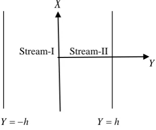
Consider a steady, two-dimensional laminar fully developed free convective flow in an open ended vertical channel filled with purely viscous fluid. The X-axis is taken vertically upward, and parallel to the direction of buoyancy, and the
Y-axis is normal to it (Fig. 1). Walls are maintained at a constant temperature and the fluid properties are assumed to be constant. The channel is divided into two passages by means of thin, perfectly conducting plane baffle and each stream will have its own pressure gradient and hence the velocity will be individual in each stream.
X
Stream-I Stream-II
Y
Y= −h Y =h
Fig. 1: Physical Configuration.
The governing equations for velocity, temperature and concentration are
Stream-I
(
2)
2 1
1 ( 0) 2 0
T W C
d U dP
g T T g C C
dX dY
ρ β − +ρ β − − +µ = (1)
2 2
1 1
2 0
P
d T dU
C dY
dY
ν α
+ =
(2)
2
2 0
d C
D k C
dY − = (3)
Stream-II
(
2)
2 2
2 2 0
T W
d U dP
g T T
dX dY
ρ β − − +µ = (4)
2 2
2 2
2 0
P
d T dU
C dY
dY
ν α
+ =
Subject to the boundary conditions on velocity, temperature and concentration as
1 0
U = ,
1
1 W
T =T ,C=C1, at Y = −h
2 0
U = ,
2
2 W
T =T , at Y =h
1 0
U = , U2 =0, T1=T2, dT1 dT2
dY = dY , C=C2, at *
Y =h (6)
Introducing the following non-dimensional variables in the governing equations for velocity, temperature and concentration as, 1 i i U u U
= , 2
1 2 i W i W W T T T T
θ = −
− , 3 2 T g Th Gr β υ ∆ = , 3 2 C C g Ch G β υ ∆
= , 1
Re U h
υ = , 2 1 U Br k T µ = ∆ , 2 1 dp h p dX U µ = , 0 1 0 C C C C
φ= −
− , ∆ =T TW2 −TW1, ∆ =C C1−C0,
*
* y
Y h
= , Y y h
= (7)
one obtains the momentum, energy and concentration equations corresponding to stream-I and stream-II as
Stream-I 2
1
1
2 T c 0
d u
GR GR p
dy + θ + φ− = (8)
2 2 1 1 2 0 d du Br dy dy
θ
+ =
(9)
2 2
2 0
d
dyφ α φ− = (10)
Stream-II 2
2
2
2 T 0
d u
GR p
dy + θ − = (11)
2 2 2 2 2 0 d du Br dy dy
θ
+ =
(12)
Subject to the boundary conditions,
1 0
u = , θ =1 1, φ=1, at y= −1
2 0
u = , θ =2 0, at y=1
1 0
u = , u2 =0, θ1=θ2, d 1 d 2
dy dy
θ θ
= , φ=n, at y=y* (13)
where
2 ,
kh D
α = 2 0
1 0 C C n C C − = − 3. SOLUTIONS
The solution of equation (10) using boundary condition (13) become
( )
( )
1 2
B Cosh y B Sinh y
φ= α + α
(14)
Equations (8), (9), (11) and (12) are coupled non-linear ordinary differential equations and hence closed form solutions can not be found. However approximate solutions can be found by using the regular perturbation method. The perturbation parameter Br is usually small and hence regular perturbation method can be strongly justified. Adopting this technique, solutions for velocity and temperature are assumed in the form
( )
( )
( )
2( )
0 1 2 ...
i i i i
u y =u y +Br u y +Br u y + (15)
( )
( )
( )
2( )
0 1 2 ...
i y i y Br i y Br i y
Substituting equations (15) and (16) in equations (8), (9), (11) and (12) and equating the coefficients of like power of
Br to zero and one, we obtain the zero and first order equations as
Stream-I Zeroth order equations
2 10 2 0 d dy θ
= (17)
2 10
10
2 T c 0
d u
GR GR p
dy + θ + φ− = (18)
First order equations
2 2 10 11 2 0 du d dy dy
θ
+ =
(19)
2 11
11
2 T 0
d u GR
dy + θ = (20)
Stream-II Zeroth order equations
2 20 2 0 d dy θ
= (21)
2 20
20
2 T 0
d u
GR p
dy + θ − = (22)
First order equations
2 2 20 21 2 0 du d dy dy
θ
+ =
(23)
2 21
21
2 T 0
d u GR
dy + θ = (24)
The corresponding boundary conditions reduces to Zeroth-order
10 0
u = , θ =10 1, φ=1, at y= −1
20 0
u = , θ =20 0, at y=1
10 0
u = , u20=0, θ10=θ20, d 10 d 20
dy dy
θ = θ
, φ=n, at y=y* (25)
First order
11 0
u = , θ =11 0 at y= −1
21 0
u = , θ =21 0 at y=1
11 0
u = , u21=0,θ11=θ21, d 11 d 21
dy dy
θ θ
= at y= y* (26)
The solutions of zeroth and first order equations (17) to (24) using the boundary conditions as given in equations (25) and (26) are Zeroth-order
Stream-I
10 z y1 z2
θ = +
(27)
( )
( )
2 3
10 2 1 1 2 4 5
u =A +A y+r y +r y +r Cosh αy +r Sinh αy
(28)
Stream-II
20 z y3 z4
θ = +
(29)
2 3
20 4 3 5 6
u =A +A y+r y +r y
(30)
Stream-I
2 3 4 5 6
11 G2 G y1 p y1 p y2 p y3 p y4 p y5
θ = + + + + + + +p Cosh6
(
2αy)
(
)
( )
( )
( )
( )
( )
( )
7 8 9 10
2 2
11 12 13
2
p Sinh y p Cosh y p Sinh y p yCosh y
p ySinh y p y Cosh y p y Sinh y
α α α α
α α α
+ + + +
+ + + (31)
(
)
(
)
( )
( )
( )
( )
( )
( )
2 3 4 5 6 7 8
11 6 5 1 2 3 4 5 6 7
8 9 10 11
2 2
12 13 14 15
2 2
u G G y R y R y R y R y R y R y R y
R Cosh y R Sinh y R Cosh y R Sinh y
R yCosh y R ySinh y R y Cosh y R y Sinh y
α α α α
α α α α
= + + + + + + + +
+ + + +
+ + + + (32)
Stream-II
2 3 4 5 6
21 G4 G y3 q y1 q y2 q y3 q y4 q y5
θ = + + + + + +
(33)
2 3 4 5 6 7 8
21 8 7 1 2 3 4 5 6 7
u =G +G y+S y +S y +S y +S y +S y +S y +S y
(34)
The constants appeared in all the above equations are presented the section Appendix
4. RESULTS AND DISCUSSIONS
The purpose of this study is to bring out the effect of position of the baffle on the flow and heat transfer in a vertical channel. Nonlinear coupled ordinary differential equations governing the flow have been solved by regular perturbation method. The solutions are found up to the order of one of the perturbation parameter. The ratio of Grashof number to Reynolds number GRT, modified Grashof number to Reynolds number GRC,pressure gradientp, and chemical reaction parameter α, are fixed as 5, 5, -5 and 0.5 respectively, for all the graphs except the varying one.
The effect of ratio of Grashof number to Reynolds numberGRTon the velocity and temperature is shown in figure 2a, b, c and figure 3 a, b, c at all the three different baffle positions
(
y*= −0.8, 0, 0.8)
. As the ratio of Grashof number to Reynolds number increases, the velocity and temperature increases at the hot (left) wall and cold (right) wall at all the baffle position. It is seen from figure 2b and figure 3b that the maximum point of velocity and temperature is in stream-I, however the maximum velocity and temperature should be equal in both the streams when the baffle position is in the center of the channel. For the present problem this is not true because the left wall is at higher temperature compared to the right wall, hence the convection is high in stream-I when compared to stream-II. Further it is well-known that since Grashof number is the ratio of buoyancy force to viscous force, increase in Grashof number increase the buoyancy force and hence increases the flow. Therefore as the ratio of Grashof number to Reynolds number increases velocity and temperature increases at all baffle position in both the streams.The effect of Brinkman numberBron the velocity and temperature fields are shown in figures 6 a, b, c and figures 7 a, b, c respectively. As the Brinkman number increases both the velocity and temperature increases in both the streams at all baffle positions. One can see from temperature equation that increase in Brinkman number increases the viscous dissipation and hence the temperature is enhanced.
5. CONCLUSION
The effect of first order chemical reaction in a vertical double passage channel filled with purely viscous fluid is investigated. According to the results, the following conclusions are drawn:
1. Increasing the values of the ratio of Grashof number to Reynolds number, ratio of modified Grashof number to Reynolds number increases the velocity and temperature in both the streams at different baffle position. 2. Increase in the Brinkman number, enhances the velocity and temperate in both the streams.
3. Increase in the chemical reaction parameter suppresses the velocity, temperate and concentration in stream-I and remains invariant in stream-II at different positions of the baffle.
ACKNOWLEDGMENT
The authors greatly acknowledge the funding support from the Major Research project supported by University Grants Commission India (Grant No. 41-774/2012 (SR)).
NOMENCLATURE
h channel width
*
h width of passage
*
y baffle position
p
c dimensionless specific heat at constant pressure
g acceleration due to gravity
Gr Grashof number
3
2
h gβ T
ν
∆
T
β coefficient of thermal expansion
C
β coefficient of concentration expansion
C concentration in Stream-I
0
C reference concentration
1
U reference velocity
D diffusion coefficient
1, 2
T T dimensional temperature
1, 2
w w
T T temperatures at the boundaries
1, 2
U U dimensional velocities
1, 2
u u non-dimensional velocities
Gc Modified Grashof Number
3
2 g c C hβ
υ
∆
k thermal conductivity of fluid
Br Brinkman number
2 1 1 u K T µ ∆
p non-dimensional pressure gradient
2 1 h p X Uµ ∂ ∂ T
GR dimensionless parameter
Re T Gr GR = C
GR dimensionless parameter
Re C Gc GR =
Re Reynolds number U h1
γ p
C specific heat at constant pressure
α chemical reaction parameter
T
∆ difference in temperature
C
∆ difference in concentration
Br perturbation parameter
i
θ non-dimensional temperature 2
1 2 i W W W T T T T − −
υ kinematic viscosity
φ non-dimensional concentrations ρ density
µ viscosity
SUBSCRIPTS
i refer quantities for the fluids in stream-I and stream-II, respectively.
6. REFERENCES
[1] Shi. X., and Khodadadi. J. M., Laminar Natural Convection Heat Transfer in a Differentially Heated Square Cavity Due to a Thin Fin on the Hot Wall. Journal of Heat Transfer, vol. 125, pp.624-634, 2003.
[2] Mariani, V., and Moura, I., Belo, Numerical Studies of Natural Convection in a Square Cavity, Thermal Engineering, vol. 5, pp. 68-72, 2006.
[4] Yao, L.S., A note on Prandtl’s transposition theorem, ASME. J Heat Transfer, vol. 110, pp. 503-507, 1988. [5] Moulic, S.G. and Yao, L.S., Mixed convection along a wavy surface, ASME. J Heat Transfer, vol. 111,
pp. 974-979, 1989.
[6] Nasiruddin and Siddiqui, M.H.K., Heat Transfer augmentation in a heat exchanger tube using a baffle, Int. J. Heat and Fluid Flow, vol. 28, pp. 318-328, 2007.
[7] Zhou, S., Corquodale, J. Mc., and Vitasovic, Z., Influences of density on circular clarifiers with baffles. J. Environmental Engineering, ASCE. Vol. 118, pp. 829-847, 1992.
[8] Rathish Kumar, B.V., Sing, P., Murthy, P.V.S.N., Effect of surface undulations on natural convection in a porous surface cavity, ASME J. Heat Transfer,vol. 119, pp. 848-851, 1997.
[9] Rathish Kumar, B.V., Murthy, P.V.S.N., Sing, P., Free convection heat transfer from an isothermal wavy surface in a porous enclosure, Int. J. Numer. Mech. Fluids, vol. 28, pp. 633-661, 1998.
[10] Murthy, P.V.S.N., Rathish Kumar, B.V., Sing, P., Natural convection heat transfer from a horizontal wavy surface in a porous enclosure, Numer. Heat Transfer Part A,vol. 31, pp. 202-221, 1997.
[11] Rathish Kumar, B.V., Shalini, Free convection in a non-Darcian wavy porous enclosure. Int. J. Engg. Sci.vol. 41, pp. 1827-1848, 2003.
[12] Guo, Z.Y., Wang, B.X., A novel concept for convective heat transfer enhancement. Int. J. Heat MassTransfer,
vol. 41, pp. 2221-2225, 1998.
[13] Salah El-Din, M.M., :Fully developed laminar convection in a vertical double-passage channel. Appl. Ener., Vol. 47, pp. 69-75, 1994.
[14] Salah El-Din, M.M.,: Effect of viscous dissipation on fully developed laminar mixed convection in a vertical double-passage channel. Int. J. Therm. Sci. vol. 41, pp. 253-259, 2002.
[15] Fasogbon, P.F., analytical study of heat and mass transfer by free convection in a two-dimensional irregular channel. Int. J. Appl. Math. Mech, vol. 6, pp. 17-37, 2010.
[16] Srinivas, S., Muthuraj, R., Effect of chemical reaction and space porosity on MHD mixed convective flow in a vertical asymmetric channel with peristalsis, Mathematical and computer Modeling. vol.54, pp. 1213-1227, 2011. APPENDIX
(
)
( )
(
)
( )
( )
(
)
(
)
( )
( )
(
( )
)
(
)
1 2 * * , * * * *Sinh y n Sinh n Cosh Cosh y
B B
Sinh y Cosh Sinh Cosh y Sinh y Cosh Sinh Cosh y
α α α α
α α α α α α α α
+ −
= =
+ + , 1
1 2
z = − , 2 1 2
z =
3
1 2
z = − , 4 1 2
z = ,
(
2)
1
2 T
p GR C
r = − , 1
2
6 T
GR C
r = − , 1
3 2
c
GR B r
α
= − , 2
4 2
c
GR B r
α
= − ,
(
4)
5
2 T
p GR C
r = −
3 6 6 T GR C
r = − ,
(
(
) (
)
(
(
)
( )
)
(
(
)
( )
)
)
2 3
1 2 3 4
1
* 1 * 1 * *
1 *
r y r y r Cosh y Cosh r Sinh y Sinh
A
y
α α α α
− + + + − + +
= −
+
( )
( )
2 1 1 2 3 4
A =A − + −r r r Cosh α +r Sinh α ,
(
) (
)
(
)
2 3
5 6
3
1 * 1 *
* 1
r y r y
A
y
− + −
=
− , A4 = − − −A3 r5 r6
(
2 2 2 2 2)
1 4 3
1
2
4
A r r
p = − + α − α , 1 1
2
2 3
A r
p = − ,
(
)
2 1 1 2 3
4 6
12
r A r
p = − + , 1 2
4
3 5
r r p = −
, 2 2 5 3 10 r
p = − ,
(
)
2 2 3 4 6
8
r r
p = − + , 3 4
7
4
r r
p = − ,
(
)
2
1 4 1 3 2 4
8 3
2A r 8r r 36r r
p α α
α
− +
= − ,
(
2)
1 3 1 4 2 3
9 3
2A r 8r r 36r r
p α α
α
− +
= − , p10
(
4r r1 4α 224r r2 3)
α −
= − , p11
(
4r r1 3α 224r r2 4)
α −
= − , 2 4
12
6r r p α = − 2 3 13
6r r p α = − , 2 3 1 2 A
q = − , 3 5
2
2 3
A r
q = − ,
(
)
2 5 3 6 3
2 3
6
r A r
q = − + , 5 6
4
3 5
r r
q = − ,
2 6 5 3 10 r
q = −
( )
( )
( )
( )
( )
( )
( )
( )
1 2 3 4 5 6 7 8
1
9 10 11 12 13
2 2
p p p p p p Cosh p Sinh p Cosh
T
p Sinh p Cosh p Sinh p Cosh p Sinh
α α α
α α α α α
− + − + + − + = − − − + + − ,
(
)
2 1 2 3 4 5
(
)
(
)
(
)
(
)
(
)
(
)
(
)
(
)
2 3 4 5 6 2 3 4 5 6
3 1 2 3 4 5 1 2 3 4 5 6 7
2 2
8 9 10 11 12 13
* * * * * * * * * * 2 * 2 *
* * * * * * * * * *
T q y q y q y q y q y p y p y p y p y p y p Co sh y p S in h y
p Cosh y p Sinh y p y Cosh y p y Sinh y p y Cosh y p y Sinh y
α α
α α α α α α
= + + + + − − − − − − − − − − − − −
(
)
(
)
(
)
(
)
(
(
)
(
)
)
(
)
(
)
(
)
(
(
)
(
)
)
2 3 4 5 2 3 4 5
4 1 2 3 4 5 1 2 3 4 5 6
7 8 9 10
2
11 12
13
2 * 3 * 4 * 5 * 6 * 2 * 3 * 4 * 5 * 6 * 2 2 *
2 2 * * * * * *
* * * 2 * * * *
2 *
T q y q y q y q y q y p y p y p y p y p y p S in h y
p Cosh y p Sinh y p Cosh y p y Sinh y Cosh y
p y Cosh y Sinh y p y Cosh y y Sinh y
p y Sinh
α α
α α α α α α α α α
α α α α α α
α
= + + + + − − − − − −
− − − − +
− + − +
−
(
(
)
2(
)
)
* * *
y +αy Cosh αy
(
4 1 2 3 4)
1
*
2
y T T T T T
G = − + − − − , 2
(
1 2 3 4(
1 *)
)
2
T T T T y
G = + + + − , 3
(
1 2 3 4(
1 *)
)
2
T T T T y
G = − + + − + , G4 =T2−G3
2 1 2 T GR G
R = − , 1
2
6 T
GR G
R = − , 1
3
12 T
GR p
R = − , 2
4
20 T
GR p
R = − ,
3 5 30 T GR p
R = − , 4
6
42 T
GR p
R = − , 5
7
56 T
GR p R = −
6 8 2 4 T GR p R α
= − , 7
9 2 4 T GR p R α = − ,
(
)
28 11 12
10 4
2 6 T
p p p GR
R α α
α
− +
= − ,
(
)
2
9 10 13
11 4
2 6 T
p p p GR
R α α
α
− +
= −
(
10 13)
12 3
4 T
p p GR
R α
α −
= − ,
(
11 12)
13 3
4 T
p p GR
R α
α −
= − , 12
14 2
T
GR p R
α
= − , 13
15 2
T
GR p R
α
= − , 4
1
2 T
GR G S = −
3 2 6 T GR G
S = − , 1
3
12 T
GR q
S = − , 2
4
20 T
GR q
S = − , 3
5
30 T
GR q
S = − , 4
6
42 T
GR q
S = − , 5
7
56 T
GR q S = −
( )
( )
( )
( )
( )
( )
( )
( )
1 2 3 4 5 6 7 8 9 10
5
11 12 13 14 15
2 2
R R R R R R R R Cosh R Sinh R Cosh
T
R Sinh R Cosh R Sinh R Cosh R Sinh
α α α
α α α α α
− + − + − + + − + = − − − + + −
(
)
(
)
(
)
(
)
(
)
(
)
(
)
(
)
2 3 4 5 6 7 8
1 2 3 4 5 6 7 8 9 10
7 2 2
11 12 13 14 15
* * * * * * * 2 * 2 * *
* * * * * * * * *
R y R y R y R y R y R y R y R Cosh y R Sinh y R Cosh y
T
R Sinh y R y Cosh y R y Sinh y R y Cosh y R y Sinh y
α α α
α α α α α
+ + + + + + + + + = + + + + + 7 5 5 1 * T T G y − =
+ , 7 6 8
1 * T T G y − =
− , G6=T5+G5, G8 =T6−G7.