Interactive Workshop on the Industrial Application of
Verification and Testing,
ETAPS 2019 Workshop
(InterAVT 2019)
Formal Verification in the Loop to Enhance Verification of
Safety-Critical Cyber-physical Systems
Cinzia Bernardeschi, Andrea Domenici, Sergio Saponara
9 pages
Guest Editors: Anila Mjeda, Stylianos Basagiannis, Goetz Botterweck
Formal Verification in the Loop to Enhance Verification of
Safety-Critical Cyber-physical Systems
∗Cinzia Bernardeschi, Andrea Domenici, Sergio Saponara
Dipartimento di Ingegneria dell’Informazione Universit`a di Pisa, Italy
Abstract: Formal verification may play a central role in the development of safe controllers, such as those found in electric drives or (semi-)autonomous vehicles, whose complexity arises from the coexistence of mechanical and electrical subsys-tems with sophisticated electronic controllers that must implement high-level con-trol policies according to different driving modes, while optimizing several objec-tives, such as safety first and foremost, efficiency, and performance among others. Model-driven development resorts to simulation to assess how well the various re-quirements and constraints are satisfied, but there is a growing awareness that more rigorous methods are needed to achieve the required levels of safety. This paper proposes a conceptual framework for the development of complex systems based on (i) higher-order logic specification, (ii) verification by theorem proving, and (iii) tight integration of verification with model-driven development and simulation. This framework addresses both digital and analog systems, as illustrated with some ex-amples in different fields including implantable biomedical systems, autonomous vehicles, and electric valve actuation.
Keywords:embedded systems, model-based design, formal verification
1
Introduction
Cyber-Physical Systems (CPS) for safety-critical applications such as electrified and autonomous vehicles need computation-intensive and distributed controllers to manage complex HW-SW systems, where stringent Safety Integrity Levels are needed. For example, ASIL-D requires a failure rate below 10 FIT (i.e., 10 failures each billion of hours). CPS developers must ensure such safety requirements while facing the complexity of these systems and of their interaction with an environment whose behavior is seldom fully predictable. In addition, CPS development is constrained by marketing requirements.
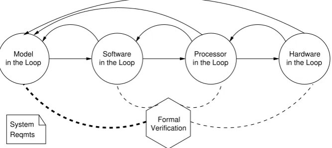
The state-of-the-art methods for safety-critical CPSs consist in a hierarchical simulation work-flow. In the model-in-the-loop (MIL) stage, an abstract model of a CPS, expressed in some modeling language such as Simulink or Modelica, is executed; in the software-in-the-loop (SIL) stage, the control algorithms are implemented in a programming language and executed within the simulation environment, then in the processor-in-the-loop (PIL) stage the implemented
algo-∗Work partially supported by the Italian Ministry of Education and Research (MIUR) in the framework of the
rithms run on the target processor mounted on a development board, and finally, in the hardware-in-the-loop (HIL) stage, they run on the target processor mounted in the deployed ECU, inter-acting with an emulated physical plant, which provides and accepts the same physical signals as the actual one. The highest cost in this approach lies probably in the time needed to achieve the required levels of fault coverage and failure rate. And anyway, simulation alone can never guarantee the absence of faults. We proposeFormal Verification in the Loop(FVL) as a way to integrate formal verification in the development of CPSs, thus providing much greater confidence on requirements compliance with respect to simulation alone, and reducing costs.
As Figure1suggests, formal verification can have a role in all development stages. Each stage works on a system model at a given level of abstraction, and the model’s compliance to functional and non-functional requirements can be proved, after the model is recast in a formally verifiable language. For instance, many applications of formal methods to hardware analysis have been reported, including model checking [BCDS13], stochastic activity networks [BCD11,SSS15], and higher-order logic (HOL) [ALAA14, SRC97]. Temporal logic has been used for control software synthesis [RXO+14].
The present work is focused on verification of the initial system model, i.e., on the MIL stage. More specifically, the verification method is based on computer-assisted theorem proving of HOL theories.
in the Loop Processor in the Loop
Software
in the Loop Hardware
Verification Formal in the Loop
Model
System Reqmts
Figure 1: Formal Verification in the Loop.
2
Formal verification in the loop
A control algorithm can be specified as a set of equations, or a switched system (e.g., finite-state machines), or a combination of both. It can then beimplementedin HW, or SW, or both. Electronic hardware, in turn, can be hardwired or programmable (e.g., FPGAs). Finally, the controller components interact with the plant through sensors and actuators. The challenge in the application of FVL methods is developing new verification techniques that can deal with this variety of design approaches.
The proposed FVL workflow can be summarized as follows: (i) MIL simulation is used for an initial validation of the overall system model, referred to as theinitialmodel in the following; (ii) selected components of the system, usually the control ones, are specified in a logic-based language; (iii) safety properties are formally verified; and (iv) the further stages of SIL, PIL, and HIL simulation follow.
Points (ii) and (iii) above are the FVL stage proper. The translation phase requires a thorough analysis of the initial model, which leads to a better understanding of constraints and assump-tions and may reveal weaknesses that may have escaped the simulation-based validation. This phase produces a theory in two parts: a definition of the system’s structure and behavior, and a definition of the system’s constraints and requirements in the form of assertions (theorems) to be proved. The verification phase relies on an interactive theorem prover, a software en-vironment embodying the inference rules of some deduction system (in this case the sequent calculus[ORSV95]). The theorem prover carries out complex formula transformations, ensur-ing a correct execution of each inference step chosen by the developer. The causes of a failed proof must be analyzed, since they may lie in an incorrect translation from the initial model or system requirements to HOL, or in an incorrect representation of the intended design in the ini-tial model, or finally in some flaw in the intended design. In any case, a failed proof provides useful feedback to the MIL stage.
Two important issues must be considered. First, the logic-based specifications must match the model developed in the initial MIL stage. It would be unreasonable to start from a model in a logic-based language, since the system developers should use the standard, well-proven system modeling languages and tools. It is then the task of averification engineerto recast the model in a logic language, with the support of the system engineers. A “verification engineer” is an expert in the practical application of formal verification tools, not a full-fledged theoretician but an engineer with a specific training.
Second, even if a single component is to be formally verified, verification must take the whole system into account. Specifying the whole system in a logic language might be too expensive, but it is possible to expressassumptionson the whole system and verify each component against them.
3
Higher-order logic for specification and verification
reason about function properties, thus providing developers with the means to describe systems at various levels of abstraction.
The authors’ experience has focused on the Prototype Verification System (PVS) [ORS92] framework, in which a system can be (i) described as a composition of logic theories in a HOL language, (ii) simulated, and (iii) formally proved to satisfy safety requirements using the interac-tive theorem prover. Simulation of a PVS-specified system is made possible by the PVSioground evaluator[Mu˜n03], which translates purely declarative function definitions into executable code. Thanks to this capability, simulation can be used to validate the specification (“doing the right system”), which in turn is formally verified (“doing the system right”). Further, simulation can be used to validate the human-machine interface, a fundamental component in many application fields, such as automotive, aerospace, and medical applications.
A prominent feature of HOL is its fundamental nature, as opposed to the more specialized formalisms, such as those based on the state-machine paradigm, or on process algebras. HOL applies equally well to discrete-time and continuous-time systems, so it suits the needs of CPSs. The downside of this generality might be the need of developing from scratch application-specific theories, but the PVS environment provides a large number of off-the-shelf theories that system developers can build upon.
In the rest of this section, some examples illustrate how the above considerations can be put to work.
3.1 Pacemaker: a complex hybrid system controller
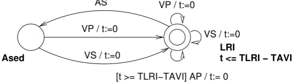
A pacemaker is a complex controller that supports, and at times overrides, the physiological con-trol of the heart. A pacemaker had been modeled [JPM+12] as a network of five communicating timed automata, of which one of the simplest is shown inFigure 2. A method was developed to translate a network of timed automata into a PVS theory [BDM18]. This theory was then co-simulated along with a Simulink model of the human heart in order to explore relevant sce-narios. Further, formal verification with the PVS theorem prover demonstrated specific safety aspects of the pacemaker design, such as showing that the pacemaker response to heart signals is deterministic.
LRI
t <= TLRI − TAVI AS VP / t:=0
VS / t:=0
[t >= TLRI−TAVI] AP / t:= 0 Ased
VP / t:=0
VS / t:=0
Figure 2: A timed automaton in the pacemaker model.
MTDB16], which produces PVS code from a graphical representation of a TA.
3.2 Water tank: finding constraints with simple math
In [BD16], basic mathematical reasoning was used to find constraints that guarantee a correct behavior of a simple non-linear system. The electric exhaust valve of a water tank fed with a constant flow receivesopen, close, or neutralcommands issued by a controller according to below-reference, above-reference, or at-reference signals, respectively, received from a level sensor. The valve cross section varies linearly with time. In spite of its simplicity, this system is hard to analyze with the standard approaches of linear control theory, so in a practical setting it would most likely be studied by simulation. A formal description, however, can be obtained by defining the relevant quantities as in the following excerpt:
% input and output flowrates w_in(t): real
w_out(t): real = C*v(t)
% derivatives of v(t) and l(t) valve_law: AXIOM deriv(v) = k;
level_law: AXIOM deriv(l) = w_in - w_out
wherev,k,l,w in,w out, and C are the valve cross section, the sensor output, the water level, the inflow, the outflow, and the ratio of flow to valve cross section, respectively, which have been defined elsewhere. This formalization, together with off-the-shelf theories on algebra and derivation, made it possible to find bounds on the initial level, depending on the inflow, that avoid overflow or depletion. An example of safety property follows:
no_depletion: THEOREM forall (t: real):
(v = (lambda (x): (-1)*x + 1) and w_in = const_fun(0) and L_i > L1 + C/2 IMPLIES
l(t) >= L1)
where thelambdaexpression represents a linear function,const fun(0)is the function identically equal to zero,L iandL1are the reference and minimum level, respectively.
3.3 Simple autonomous vehicle: from control theory to HOL
characteristic polynomial, proving their correctness with respect to the assumptions, then com-puting the eigenvalues and proving their correctness. In the process, a sufficient condition on the value ofkwas found.
4
The Challenge
The case studies discussed inSection 3show successful applications of FVL methodologies to simple CPSs. With more complex systems, such as controllers for electrified and autonomous vehicles, the challenge is using the formal verification methodologies discussed above, in addi-tion to tradiaddi-tional simulaaddi-tion and testing, to improve their reliability. Classic verificaaddi-tion flows typically use one of these approaches: (i) applying formal verification, but only of some con-trol parts (e.g, the logic driver of a battery management system (BMS) [BBC+14]); (ii) using simulation-based HIL; or (ii) only verification to test complete systems, such as the complex HIL platforms proposed for a complete BMS in [HPB13] and [KSD+17]. However, relying only on simulation- or emulation-based HIL has several limits in terms of coverage of corner cases and long time for exhaustive testing. To overcome these limits we propose mixing formal veri-fication with simulation-based techniques, thus creating a new Formal-Veriveri-fication-in-the-Loop methodology. As on-going work, we are applying Formal Verification in the Loop to testing typical safety-critical sub-systems of electrified vehicles.
Bibliography
[ACHH93] R. Alur, C. Courcoubetis, T. A. Henzinger, P. H. Ho. Hybrid automata: An algorith-mic approach to the specification and verification of hybrid systems. In Grossman et al. (eds.),Hybrid Systems. Pp. 209–229. Springer Berlin Heidelberg, Berlin, Heidelberg, 1993.
doi:10.1007/3-540-57318-6 30
[ALAA14] A. A. Almeida, C. H. Llanos, J. Arias-Garc´ıa, M. Ayala-Rinc´on. Verification of Hardware Implementations Through Correctness of Their Recursive Definitions in PVS. InProceedings of the 27th Symposium on Integrated Circuits and Systems De-sign. SBCCI ’14, pp. 14:1–14:8. ACM, New York, NY, USA, 2014.
doi:10.1145/2660540.2660982
[BBC+14] F. Baronti, C. Bernardeschi, L. Cassano, A. Domenici, R. Roncella, R. Saletti. De-sign and Safety Verification of a Distributed Charge Equalizer for Modular Li-Ion Bat-teries.IEEE Trans. Industrial Informatics10(2):1003–1011, 2014.
doi:10.1109/TII.2014.2299236
[BCD11] C. Bernardeschi, L. Cassano, A. Domenici. Failure Probability and Fault Observabil-ity of SRAM-FPGA Systems. In International Conference on Field Programmable Logic and Applications (FPL2011). Pp. 385–388. IEEE, sep 2011.
[BCDS13] C. Bernardeschi, L. Cassano, A. Domenici, L. Sterpone. Unexcitability analysis of SEus affecting the routing structure of SRAM-based FPGAs. In Proceedings of the 23rd ACM International Conference on Great Lakes Symposium on VLSI. GLSVLSI ’13, pp. 7–12. ACM, New York, NY, USA, 2013.
doi:10.1145/2483028.2483050
[BD16] C. Bernardeschi, A. Domenici. Verifying safety properties of a nonlinear control by interactive theorem proving with the Prototype Verification System.Information Pro-cessing Letters116(6):409–415, 2016.
doi:10.1016/j.ipl.2016.02.001
[BDM18] C. Bernardeschi, A. Domenici, P. Masci. A PVS-Simulink Integrated Environment for Model-Based Analysis of Cyber-Physical Systems.IEEE Transactions on Software Engineering44(6):512–533, 2018.
doi:10.1109/TSE.2017.2694423
[DFP18] A. Domenici, A. Fagiolini, M. Palmieri. Integrated Simulation and Formal Verification of a Simple Autonomous Vehicle. In Cerone and Roveri (eds.), Software Engineer-ing and Formal Methods. Lecture Notes in Computer Science 10729, pp. 300–314. Springer International Publishing, Cham, 2018.
doi:10.1007/978-3-319-74781-1 21
[FH07] M. Fr¨anzle, C. Herde. HySAT: An efficient proof engine for bounded model checking of hybrid systems.Formal Methods in System Design30(3):179–198, Jun 2007. doi:10.1007/s10703-006-0031-0
[FLD+11] G. Frehse, C. Le Guernic, A. Donz´e, S. Cotton, R. Ray, O. Lebeltel, R. Ripado, A. Girard, T. Dang, O. Maler. SpaceEx: Scalable Verification of Hybrid Systems. In Gopalakrishnan and Qadeer (eds.),Proc. 23rd International Conference on Computer Aided Verification (CAV). LNCS 6806, pp. 379–395. Springer, 2011.
doi:10.1007/978-3-642-22110-1 30
[FLP+10] J. Fitzgerald, P. G. Larsen, K. Pierce, M. Verhoef, S. Wolff. Collaborative Modelling and Co-simulation in the Development of Dependable Embedded Systems. In M´ery and Merz (eds.),Integrated Formal Methods. Pp. 12–26. Springer Berlin Heidelberg, Berlin, Heidelberg, 2010.
doi:10.1007/978-3-642-16265-7 2
[FMQ+15] N. Fulton, S. Mitsch, J.-D. Quesel, M. V¨olp, A. Platzer. KeYmaera X: An axiomatic tactical theorem prover for hybrid systems. InInternational Conference on Automated Deduction. Pp. 527–538. Springer, 2015.
doi:10.1007/978-3-319-21401-6 36
[HPB13] H. H., M. Pl¨oger, J. Bracker. Hardware-in-the-Loop Test of Battery Management Sys-tems.IFAC Proceedings Volumes 46(21):658 – 664, 2013. 7th IFAC Symposium on Advances in Automotive Control.
[JPM+12] Z. Jiang, M. Pajic, S. Moarref, R. Alur, R. Mangharam. Modeling and Verification of a Dual Chamber Implantable Pacemaker. In Flanagan and K¨onig (eds.),Tools and Algorithms for the Construction and Analysis of Systems. Lecture Notes in Computer Science 7214, pp. 188–203. Springer Berlin Heidelberg, 2012.
doi:10.1007/978-3-642-28756-5 14
[KSD+17] C. Kettenring, M. Schwalm, T. Dabrowski, M. Thiele, M. Puchta. Accelerated de-velopment and test of BMS using an emulation-based HIL. InEVS 2017 — 30th Int. Electric Vehicle Symposium and Exhibition. 2017.
[LFW+16] P. G. Larsen, J. Fitzgerald, J. Woodcock, P. Fritzson, J. Brauer, C. Kleijn, T. Lecomte, M. Pfeil, O. Green, S. Basagiannis, A. Sadovykh. Integrated tool chain for model-based design of Cyber-Physical Systems: The INTO-CPS project. In2016 2nd International Workshop on Modelling, Analysis, and Control of Complex CPS (CPS Data). Pp. 1–6. April 2016.
doi:10.1109/CPSData.2016.7496424
[LGP+14] P. G. Larsen, C. Gamble, K. Pierce, A. Ribeiro, K. Lausdahl. Support for Co-modelling and Co-simulation: The Crescendo Tool. Pp. 97–114. Springer Berlin Hei-delberg, Berlin, HeiHei-delberg, 2014.
doi:10.1007/978-3-642-54118-6 5
[MTDB16] G. Mauro, H. Thimbleby, A. Domenici, C. Bernardeschi. Extending a User Interface Prototyping Tool with Automatic MISRA C Code Generation. InProceedings of the Third Workshop on Formal Integrated Development Environment, F-IDE@FM 2016, Limassol, Cyprus. Pp. 53–66. 2016.
doi:10.4204/EPTCS.240.4
[Mu˜n03] C. Mu˜noz. Rapid prototyping in PVS. Technical report NIA 2003-03, NASA/CR-2003-212418, National Institute of Aerospace, Hampton, VA, USA, 2003.
[MZJ+14] P. Masci, Y. Zhang, P. L. Jones, P. Oladimeji, E. D’Urso, C. Bernardeschi, P. Cur-zon, H. Thimbleby. Combining PVSio with Stateflow. InNASA Formal Methods - 6th International Symposium, NFM 2014, Houston, TX, USA, April 29 - May 1, 2014. Pro-ceedings. Pp. 209–214. 2014.
doi:10.1007/978-3-319-06200-6 16
[OMCT13] P. Oladimeji, P. Masci, P. Curzon, H. Thimbleby. PVSio-web: a tool for rapid pro-totyping device user interfaces in PVS. InFMIS2013, 5th International Workshop on Formal Methods for Interactive Systems, London, UK, June 24, 2013. 2013.
doi:10.14279/tuj.eceasst.69.963.944
[ORS92] S. Owre, J. Rushby, N. Shankar. PVS: A prototype verification system. In Kapur (ed.), Automated Deduction — CADE-11. Lecture Notes in Computer Science 607, pp. 748– 752. Springer Berlin Heidelberg, 1992.
[ORSV95] S. Owre, J. Rushby, N. Shankar, F. Von Henke. Formal verification for fault-tolerant architectures: Prolegomena to the design of PVS.IEEE Transactions on Software En-gineering21(2):107–125, 1995.
doi:10.1109/32.345827
[PBDF18] M. Palmieri, C. Bernardeschi, A. Domenici, A. Fagiolini. Demo: Co-simulation of UAVs with INTO-CPS and PVSio-web. In Mazzara et al. (eds.),Software Technolo-gies: Applications and Foundations (STAF 2018). Lecture Notes in Computer Sci-ence 11176, pp. 52–57. Springer, Cham, 2018.
doi:10.1007/978-3-030-04771-9 5
[PQ08] A. Platzer, J.-D. Quesel. KeYmaera: A hybrid theorem prover for hybrid systems (sys-tem description). InInternational Joint Conference on Automated Reasoning. Pp. 171– 178. Springer, 2008.
doi:10.1007/978-3-540-71070-7 15
[RXO+14] R. Rogersten, H. Xu, N. Ozay, U. Topcu, R. M. Murray. Control Software Synthesis and Validation for a Vehicular Electric Power Distribution Testbed.J. Aerospace Inf. Sys.11(10):665–678, 2014.
doi:10.2514/1.I010167
[SRC97] M. Srivas, H. Rueß, D. Cyrluk. Hardware Verification Using PVS. In Kropf (ed.), Formal Hardware Verification: Methods and Systems in Comparison. Lecture Notes in Computer Science 1287, pp. 156–205. Springer-Verlag, 1997.
doi:10.1007/3-540-63475-4 4
[SSS15] S. A. Seshia, D. Sadigh, S. S. Sastry. Formal methods for semi-autonomous driving. In2015 52nd ACM/EDAC/IEEE Design Automation Conference (DAC). Pp. 1–5. June 2015.