Chapter 16
Deploying Microsoft Enterprise
Desktop Virtualization
In the previous chapter we reviewed deploying Microsoft VDI, a server-hosted desktop virtualization solution. In this chapter we will review deploying Microsoft Enterprise Desktop Virtualization (MED-V), a managed client-hosted desktop virtualization solution. The chapter includes a review of considerations for planning a deployment, guidance for conducting a Proof of Concept (POC), an overview of required server and client solution components, and step-by-step instructions for installing and configuring MED-V in a test environment.
In this chapter, you will learn to:
◆ Install and configure the MED-V Management Server ◆ Create and prepare a MED-V test image
◆ Create and configure a MED-V Workspace image ◆ Deploy a MED-V Workspace image
◆ Generate MED-V reports
Planning Considerations for a MED-V Deployment
At a high level, the process and steps of planning for a MED-V deployment are similar to the approach we took in our last chapter, but the specific details for each step are different. As a review, the planning steps included assessing the current environment, determining needs and requirements, defining the project scope, creating an architectural design, conducting a POC, and continuing on with a pilot and later a full deployment. Let’s review these planning steps and their specific MED-V considerations.
Assessing Your Environment
Before an organization deploys a MED-V solution, it’s important that they conduct an assess-ment of their current desktop environassess-ment. The assessassess-ment would include reviewing desktop hardware, operating systems, applications, user data and settings, network infrastructure, and management tools.
A review of the desktop hardware environment, the processor family and type, memory configuration, and hard disk storage of each desktop should be made and recorded. In addition, the Windows client operating system and versions running on each desktop, either
physically or as virtual machines, needs to be identified and recorded. All of this information is required in determining whether the current desktops meet the MED-V client system requirements and if a hardware or software upgrade may be needed.
Another necessary step is to review which corporate applications are running on each desk-top, along with their specific hardware and software dependencies. Each application will need to be evaluated to determine if it can run in a virtual machine and the application vendor sup-ports it.
An assessment of the desktop network environment is also important. Understanding where the desktops are located (main, distributed, or home office) and their associated network band-width and latency will help in determining the location of MED-V server infrastructure and how images will be initially deployed and updated.
Understanding what processes and tools are used to manage the desktop environment along with identifying current management challenges are essential. An organization will need to determine if their existing management process and tools can be used to manage the MED-V client environment or if new processes or tools will need to be evaluated and implemented. In addition, current desktop management challenges should be addressed prior to introducing a new desktop solution into the environment.
As mentioned before, Microsoft has assessment tools that can be used to assist an orga-nization in this effort. The Microsoft Assessment and Planning Toolkit can be found at
http://technet.microsoft.com/en-us/solutionaccelerators.
Determining Needs and Requirements
The next step for the organization is to determine their requirements for a MED-V implementa-tion. The data collected during the assessment step can help with this process. An organization will need to ask what problem or problems they are trying to solve. For example, is the organi-zation planning to migrate from the Windows XP to Windows 7 operating system and does it need a solution to remediate potential application-to-OS compatibility problems? Are they con-sidering deploying corporate-managed VMs to nonmanaged or employee-owned PCs? Maybe they would like to improve their desktop business-continuity and disaster-recovery capabili-ties by having the ability to rapidly and easily move a desktop PC image from one PC device to another in the event of a hardware failure, stolen PC, or disaster. This analysis will help an organization determine whether MED-V is the most appropriate solution to meet their require-ments and help guide the architecture design and implementation of the solution.
Defining Project Scope
After the organization has conducted an assessment of their environment and identified the problem(s) they are trying to solve and their specific needs, the next step is to define the scope of the MED-V deployment project. Some of the areas to consider when defining the project scope include which scenario(s) to implement first, the type and number of users and groups to target, which locations to include, and whether this effort should be part of a larger project. All of these questions should be answered to help develop the initial, mid-, and long-term scopes of the MED-V deployment project.
An organization may choose to implement the MED-V deployment project in phases, with each phase targeting a specific solution scenario and expanding the scope of users and groups over time. They may decide to initially implement a MED-V solution as a way to improve the disaster-recovery capabilities of the organization. They may also choose to use MED-V to remediate application-to-operating system compatibility issues to support a Windows Vista or Windows 7 deployment project. In this case, the MED-V project would be part of the larger
PLANNING CONSIDERATIONS FOR A MED-V DEPLOYMENT 479
Windows migration project and closely aligned with that project scope. A future plan could also include implementing a MED-V solution as a more agile way to deploy corporate desktop images to employee-owned or unmanaged desktops. Whatever the reason(s) for deploying a MED-V solution, the organization will need to define and closely align the scope of the project with its goals and needs.
Microsoft Consulting Services and Microsoft Partners can assist organizations with defining the MED-V project scope and overall planning efforts. More information regarding Microsoft Consulting Services and Partner offerings can be found athttp://www.microsoft.com/ services/microsoftservices andhttp://www.microsoft.com/virtualization/partners.
Creating a Solution Design and Architecture
Once an organization has completed the above steps, from conducting the assessment to defining the project scope, they are ready to design the MED-V solution architecture. A MED-V architecture consists of multiple server components that make up the overall solution. The number of servers needed to support a MED-V solution will depend on the organization’s current IT environment and requirements. The architectural design factors include the number of users, location of users, Active Directory domain design, number of Workspace images, existing management infrastructure, security and regulatory requirements, and High Availabil-ity needs. Let’s explore some of these factors and their effect on designing a MED-V solution architecture.
Today, Microsoft MED-V v1 is positioned and supported only for desktops that are part of an Active Directory Domain Services environment. Microsoft is planning to support nondo-main, unmanaged desktops with the next version of MED-V planned for release in 2010. A MED-V solution is called an instance and consists of a Management Server, Image Repository Server, and Reporting Server. A MED-V Management Server can belong to only one MED-V instance at a time, but the MED-V Repository Server and Database Server can be shared across multiple MED-V Management Servers. Microsoft recommends no more than 5,000 concurrent users be supported per MED-V instance. If an organization is planning to support more than 5,000 concurrent users, another MED-V instance will need to be added for each additional 5,000 users. In addition, if the organization has security or regulatory requirements that mandate the separation of specific MED-V Workspace images, they can implement additional MED-V instances to support those requirements.
The MED-V Management Server should be centrally located to provide reliable network access for its clients. A MED-V client regularly connects to the MED-V Management Server to send status and event information once a minute. The MED-V client also checks with the MED-V Management Server for Workspace updates every 15 minutes and image updates every four hours. If a client is unable to connect to a MED-V Management Server, the status and event information is queued on the client until it is able to reconnect. Microsoft does not sup-port using Failover Clustering for MED-V Management Server, so it’s imsup-portant to create a standby MED-V Management Server that can be brought online in the case of server failure. This is especially true if the MED-V Workspace is configured to require the client to be online and authenticated in order to use the MED-V Workspace. It is possible to implement MED-V Management Server on two servers. More information about implementing this type of failover support can be found in the MED-V manual.
The MED-V Management Server stores Workspace configuration metadata, which is 30 KB per Workspace. To determine the disk storage requirements for storing Workspace metadata on the MED-V Management Server, multiply the number of Workspaces by 30 KB. For example, if you have 20 Workspaces, you would multiply 20 by 30 KB, which equals
600 KB. The MED-V Management Server can be backed up and restored to the same server or a backup server using Microsoft System Center Data Protection Manager (SCDPM) or another backup and restore solution. Four XML files make up the server configuration files: ClientSettings.xml, ConfigurationFiles.xml, OrganizationalPolicy.xml, and
WorkspaceKeys.xml. The location for the data to back up isdrive letter:\microsoft
enterprise desktop Virtualization\servers\serverconfiguration.
As mentioned earlier, a Repository Server consists of a Web Server (IIS) and a file server that stores the images on a file share. The number of Web Servers (IIS) and file servers used in a MED-V solution instance will depend on the number of concurrent users, the size and number of the MED-V images, deployment and update frequency, the user location, network bandwidth, and other factors. Multiple Web Servers (IIS) can be used for a MED-V solution instance and load balanced to provide the appropriate level of scalability and performance. The placement of the Repository Servers should be close to the clients, avoiding WAN connections. This is important for the initial deployment of the MED-V image and also image updates. The disk storage requirements for the Image Repository are determined by identifying the num-ber and size of MED-V images that will be supported on a given repository. Backing up the MED-V images is also important and can be accomplished by using SCDPM or another backup and restore solution.
The Med-V Database Server stores client activity and event information. The size of an event sent by a client is around 200 bytes. The MED-V Database Server database storage requirements are determined by the number of MED-V clients, multiplied by the number of events sent by each client per day. Other database size factors include how long the data will be stored and the allocation of additional space for unknown events or circumstances.
Organizations will need to determine how the MED-V client software and images will be deployed and updated on the client. There are different options to choose from, including using the MED-V solution infrastructure, existing client management solutions, and removable media (DVD and USB storage). For example, an organization could deploy the MED-V client software by making it part of their corporate Windows image, deploying it using ESD or with removable media. The initial MED-V image can be deployed to the client by using the MED-V Manage-ment Server, prestaging it to the client using ESD or by removable media (DVD and USB stor-age). The Med-V images will also need to be updated, which can be accomplished by using the MED-V Management Server. Some organizations may also decide to update the client operating system and applications running in the MED-V image by using their corporate ESD solution.
Implementing a MED-V POC
Once the solution design and architecture are completed, the next step is to test the solution in a Proof of Concept (POC) lab environment. POCs are where the rubber meets the road and can vary in goals, scope, time frame, and outcome. It’s important to conduct a well-organized POC, focusing only on the goals and scope agreed on, involving the right resources, and document-ing the entire process from start to finish, so that this information can be reviewed and utilized to support later project efforts.
Depending on the goals of the POC, the architecture and server configuration of this envi-ronment can be implemented on a much smaller scale than a pilot or production deployment of the solution. For example, a typical MED-V POC involves one physical server and one to two PCs. The server would support the MED-V Management Server and Image Repository, and the PCs would support the MED-V Management Console and MED-V Client. An example MED-V POC server configuration is shown along with the MED-V POC architecture example in Figure 16.1.
PLANNING CONSIDERATIONS FOR A MED-V DEPLOYMENT 481
Figure 16.1
MED-V POC architecture
example Windows Server 2008 R2, Hyper-VPOCServer
MEDVSRV Virtual Machine Windows Server 2008
Management Server Repository Server
Database Server
PC1 Windows Vista
MED-V Client Management Console
PC2 Windows Vista
MED-V Client
At a high level, you can break the POC into four areas: preparation, installation and config-uration, testing and knowledge transfer, and review and analysis. Each area is important and will have an effect on the success of the POC and preparation for a production deployment. The knowledge transfer and testing area should be well defined in terms of what the POC team wants to learn and evaluate regarding the Microsoft POC solution. A simple but effective one-week POC action plan follows.
MED-V POC Action Plan Example
POC Preplanning Activities
◆ Conduct an initial meeting.
◆ Determine goals, scope, expected outcome, time frame, resources involved, location(s), IT infrastructure needs, and prerequisites (hardware, software, services, networking, storage, and so forth).
◆ Conduct a pre-MED-V POC meeting.
◆ Include all the required IT and business resources.
◆ Review the POC areas described above.
◆ Identify potential project showstoppers.
◆ Create an agenda for the one-week POC activities along with the responsibilities of IT and business resources participating.
POC Activities
◆ Day 1 — Kickoff meeting, installation of Windows Server 2008 R2, Hyper-V, Web Server (IIS), SQL Server, and MED-V server and client components.
◆ Conduct a MED-V POC kickoff meeting the first day of the POC. Verify that the POC prerequisites are completed and the organization is ready to begin.
◆ Present an overview of the POC project and planned day 1 activities.
◆ Begin MED-V solution server software installation.
1. Install and configure a Windows Server 2008 R2 Server with Hyper-V called POCServer.
2. Create a VM on POCServer called MEDVSRV.
3. Install Windows Server 2008 (32- or 64-bit) and prerequisite software on the VM called MEDVSRV on POCServer.
4. Install the Web Server (IIS) role on the VM called MEDVSRV on POCServer.
5. Install BITS Server Extensions feature on the VM called MEDVSRV on POCServer.
6. Install SQL Server 2008 Express on the VM called MEDVSRV on POCServer.
7. Install MED-V Management Server V1 on the VM called MEDVSRV on POCServer.
◆ Conduct daily status meeting.
◆ Day 2 — Installation of MED-V client components, and creation and testing of MED-V Workspace image.
◆ Present an overview of the planned day 2 activities.
◆ Install the MED-V client components.
1. Install MED-V client V1 and Management Console and prerequisite software on PC1 running Windows Vista (32-bit).
2. Install MED-V client V1 and prerequisite software on PC2 running Windows Vista (32-bit).
◆ Create and test MED-V Workspace images.
1. Prepare Virtual PC images for MED-V.
2. Add MED-V test images.
3. Create and configure MED-V Workspaces.
4. Test MED-V Workspaces.
5. Pack tested MED-V images.
INSTALLING THE MED-V SOLUTION 483
◆ Day 3 — Deployment of MED-V Workspace.
◆ Present an overview of planned day 3 activities.
◆ Continue to create and test MED-V Workspace images.
◆ Deploy MED-V Workspace.
1. Deploy MED-V Workspaces using the MED-V Server.
2. Update MED-V Workspaces using the MED-V Server.
3. Deploy MED-V using Deployment package on removable media.
4. Deploy MED-V using ESD for prestaged deployment.
◆ Conduct daily status meeting.
◆ Day 4 — Continuation of MED-V Workspace deployment activities and knowledge transfer.
◆ Present an overview of planned day 4 activities.
◆ Continue MED-V Workspace deployment activities.
◆ Conduct knowledge transfer activities.
◆ Conduct daily status meeting.
◆ Day 5 — Knowledge transfer and testing of MED-V environment.
◆ Present an overview of planned day 5 activities.
◆ Review MED-V troubleshooting tools.
1. Generate and review MED-V reports.
2. Run and review MED-V diagnostics.
◆ Lead MED-V Q & A discussion.
◆ Conduct end-of-POC status meeting.
Post-POC Activities
◆ Prepare report on POC activities completed, including highlights and lowlights and key findings.
◆ Develop an action plan for moving forward with the project.
Installing the MED-V Solution
The process of implementing the MED-V solution consists of installing and configuring several Microsoft software services on servers running Windows Server 2008 and personal computers running Windows Vista or Windows XP operating system. In the next two sections we will review the main installation steps required to be performed on the servers and clients that make up the MED-V solution. Figure 16.2 shows an example of the MED-V solution architec-ture that we will be installing.
Figure 16.2
Simple MED-V solution architecture
Image Repository Windows Server 2008
Web Server (IIS)
MED-V Client and Management Console
Windows Vista
MED-V Client Windows Vista g p y MED-V Server
Windows Server 2008
Database Server Windows Server 2008 SQL Server 2008 Express
g
MED-V Client Windows XP
The architecture used for this MED-V solution example consists of three servers and three clients. The reason for using three servers is to provide an example of how to isolate the required server components — MED-V Management Server, Web/Repository Server, and SQL Server — on separate servers. This may be useful in supporting scenarios that require higher performance, greater scalability, and distributed client locations. It is possible to implement all of the MED-V server components on one server running on a single instance of the server operating system or distributed on VMs, as we did for our POC.
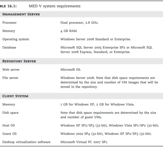
The system requirements for the MED-V version 1 are listed in Table 16.1. For the latest MED-V information, please review the Microsoft MED-V website atwww.microsoft.com/medv.
We’re making a key assumption regarding the existence of infrastructure services that are needed to support this solution, that is, AD, DNS, and DHCP. A list of the servers and clients used in this installation example is provided below. In addition, other Microsoft products, tech-nologies, and updates may also need to be installed either before or during the installation of the solution components. Examples of these include .NET Framework 3.0 SP 1, Windows Installer 4.5, and the SQL Server Native Client and SQL Server Management Objects. Please refer to the Microsoft Windows Server 2008, MED-V, Windows Vista, and Windows XP instal-lation instructions related to prerequisites for more information.
Servers
For this solution example, we will use three Windows Servers named ServerA, ServerB, and ServerC. A description of each server follows.
ServerA Image Repository Server, running Windows Server 2008 (32- or 64-bit), Web Server (IIS), and BITS Server Extensions. This server provides the platform to store and deploy MED-V Workspace images to MED-V clients.
INSTALLING THE MED-V SOLUTION 485
ServerB Database Server, running Windows Server 2008, SQL Server 2008 (32- or 64-bit). This server provides the database that is used to store MED-V client information that is collected by the MED-V Management Server. Reports can then be created from this data.
ServerC MED-V Server, running Windows Server 2008 (32- or 64-bit), MED-V Management Server V1. This server stores MED-V Server settings and Workspace policies, communicates with Active Directory to assign users and groups to Workspace images, authenticates and authorizes MED-V clients, and manages policy and Workspace deployment and updates.
Table 16.1: MED-V system requirements
Management Server
Processor Dual processor, 2.8 GHz.
Memory 4 GB RAM.
Operating system Windows Server 2008 Standard or Enterprise.
Database Microsoft SQL Server 2005 Enterprise SP2 or Microsoft SQL Server 2008 Express, Standard, or Enterprise.
Repository Server
Web server Microsoft IIS.
File server Windows Server 2008. Note that disk space requirements are determined by the size and number of VM images that will be stored in the repository.
Client System
Memory 1 GB for Windows XP, 2 GB for Windows Vista.
Disk space Note that disk space requirements are determined by the size and number of guest VMs.
Host OS Windows XP SP2/SP3 (32-bit), Windows Vista SP1/SP2 (32-bit). Guest OS Windows 2000 SP4 (32-bit), Windows XP SP2/SP3 (32-bit). Desktop virtualization software Microsoft Virtual PC 2007 SP1.
Personal Computers
For this solution example, we will use three Windows PCs named PC1, PC2, and PC3. A description of each PC is provided below.
PC1 MED-V Client and Management Console, running Windows Vista SP2 (32-bit) and MED-V Client and Management Console software. This personal computer will be used to manage the MED-V environment and test MED-V Workspace images.
PC2 MED-V Client running Windows Vista SP2 (32-bit) and MED-V Client software. This personal computer will be used to download and run MED-V Workspaces.
PC3 MED-V Client running Windows XP SP3 (32-bit) and MED-V Client software. This per-sonal computer will be used to download and run MED-V Workspaces.
Installation of the MED-V Solution Server Components
The server architecture used for this MED-V solution example comprises three servers: ServerA, the Image Repository Server; ServerB, the Database Server; and ServerC, the MED-V Management Server. The installation process begins with installing IIS and BITS Server Extensions on ServerA. The next step is to install SQL Server 2008 Express on ServerB. We then install the MED-V Management Server on ServerC. Administrator rights are required for all of these operations. As mentioned before, a key assumption made regarding the installation environment is the existence of AD, DNS, and DHCP infrastructure services that are required to support this solution. A flowchart of the server installation process is shown in Figure 16.3. Figure 16.3MED-V Server installation process flowchart
1. Install ServerA— Image Repository
Server
2. Install ServerB— Database Server
3. Install ServerC— MED-V Management
Server Microsoft MED-V Installation Steps
ServerA — Image Repository Server
The first installation step is to install the Windows Server 2008 (32- or 64-bit) on this server. Installation instructions for Windows Server 2008 can be found ontechnet.microsoft.com.
The second installation step is to add the Web Server/Internet Information Service (IIS) role. The instructions for installing Internet Information Server are listed below:
1. Open Windows Server 2008 Server Manager on ServerA.
2. Select Roles on the Server Manager hierarchy.
3. On the Roles Summary page, select Add Roles.
4. Review the Before You Begin page and click Next.
5. On the Select Server Roles page, select the Web Server (IIS) check box. Click the Add Required Features For Web Server (IIS) pop-up screen, and click Next.
6. Review the Introduction To Web Server (IIS) page, and click Next.
7. On the Select Role Services page, under the Security section, select Basic Authentication, Windows Authentication, and Client Certificate Mapping Authentication, and click Next.
8. On the Confirm Installation Selections page, review the results and click Install. The instal-lation process will begin.
INSTALLATION OF THE MED-V SOLUTION SERVER COMPONENTS 487
The third installation step adds the BITS Server Extensions feature to the server. The steps for installing this feature are as follows:
1. Open Windows Server 2008 Server Manager on ServerA.
2. Select Features on the Server Manager hierarchy.
3. On the Features Summary page, click Add Feature.
4. On the Select Features page, select the BITS Server Extensions check box. The Add Role Services Required For Background Intelligent Transfer Service (BITS)? pop-up screen will appear. Click Add Required Role Services, and then click Next.
5. On the Introduction To Web Server (IIS) page, click Next.
6. On the Select Role Services page, click Next.
7. On the Confirm Installation Selections page, review the results and click Install. The instal-lation process will begin.
8. On the Installation Results page, review the results and click Close.
The installation steps for ServerA, the Image Repository Server are now complete. The con-figuration steps for this server are provided in the upcoming section called ‘‘Concon-figuration of the MED-V Solution Server Components.’’
ServerB — Database Server
The first step is to install the Windows Server 2008 (32- or 64-bit) on this server. Installation information for Windows Server 2008 can be found ontechnet.microsoft.com.
The second step is to install SQL Server. For this installation example we will use SQL Server 2008 Express. Note that SQL Server 2005 Enterprise and SQL Server 2008 Standard and Enterprise may also be used and are a better choice for production deployments. The steps for installing the SQL Server 2008 Express are listed below:
1. Install .NET Framework 3.0 SP 1. SQL Server 2008 Express Setup requires .NET Framework 3.0 SP1 to be installed. .NET Framework 3.0 SP1 can be downloaded at
www.microsoft.com/downloads.
2. Install Windows Installer 4.5. SQL Server 2008 Express Setup requires Windows Installer 4.5 to be installed. Windows Installer 4.5 can be downloaded at
www.microsoft.com/downloads.
3. The next step is to install SQL Server 2008 Express. SQL Server 2008 Express can be down-loaded fromwww.microsoft.com/downloads. Follow these installation steps:
a. Run SQL Server Express Setup.
b. On the SQL Server Installation Center page, select Installation.
c. Select New SQL Server Stand-alone Installation or Add Features To An Existing Instal-lation. The Setup Support Rules process will run and identify any problems. If any failures are identified, correct the issues and rerun this process. If no problems are iden-tified, click OK.
e. Review the License Terms, and if you accept them, select the I Accept The License Terms check box.
f. On the Setup Support Files page, click Install.
g. For the Setup Support Rules step, see if failures were identified. If failures were iden-tified, correct the issues and rerun this process. If no problems were ideniden-tified, click Next.
h. For the Feature Selection step, select the Database Engine Services check box and click Next.
i. For the Instance Configuration step, accept the default settings and click Next. j. For the Disk Space Requirements step, review the disk usage summary and click
Next.
k. For the Server Configuration step, there are two tabs: Service Accounts and Colla-tion. For Service Accounts, select NT AuthoritySystem from the Account Name drop-down list. Accept the default setting for SQL Server Browser. For the Collation settings, accept the defaults. Click Next.
l. For the Database Engine Configuration, Account Provisioning, select Mixed Mode, and enter a password for the built-in SQL Server administrator account (SA). Specify SQL Server administrators by clicking Add Current User. Accept the default settings for Data Directories, User Instances, and FILESTREAM, and click Next.
m. For the Error And Usage Reporting step, accept the default settings and click Next. n. For the Installation Rules step, see if failures were identified. If failures were
identi-fied, correct the issues and rerun this process. If no problems were identiidenti-fied, click Next.
o. Review the Ready To Install information and click Install. The installation process will begin.
p. When the installation has completed successfully, click Next. q. Review the information on the completed page, and click Close.
The installation steps for ServerB, the Database Server are now complete. The configuration steps for this server are provided in the upcoming section called ‘‘Configuration of the MED-V Solution Server Components.’’
ServerC — MED-V Management Server
The first step is to install Windows Server 2008 (32- or 64-bit) on this server. Installation instruc-tions for Windows Server 2008 can be found ontechnet.microsoft.com.
The next step is to install the MED-V Management Server. The steps for installing the MED-V Management Server V1 are listed below.
1. Run the appropriate MED-V Server Windows Installer package,
MED-V_serverx_86_1.0.72.msifor x86 orMED-V_server_x64_1.0.72.msifor x64.
2. Review the MED-V Server Installation Wizard Welcome screen, and click Next.
3. Review the MED-V License Agreement. If you accept the licensing terms, click Next.
4. Review the Install Destination Folder setting, and click Next.
5. On the Ready To Install The Program screen, click Install.
6. On the MED-V Wizard Completed screen, deselect Launch MED-V Server Configuration Manager, and click Finish.
INSTALLATION OF THE MED-V SOLUTION CLIENT COMPONENTS 489
7. The next steps are to install the SQL Server Native Client and SQL Server Manage-ment Objects. The Microsoft SQL Server 2008 Feature Pack includes SQL Server Native Client and SQL Server Management Objects and can be downloaded at
www.microsoft.com/downloads.
a. Install SQL Server Native Client by running the filesqlcli.msi. Follow the Installation Wizard instructions, accepting all defaults.
b. Install SQL Server Management Objects by running the file
SharedManagementObjects.msi. Follow the Installation Wizard instructions, accepting all defaults.
The installation steps for ServerC, the MED-V Management Server, are now complete. The configuration steps for this server are provided in the upcoming section called ‘‘Configuration of the MED-V Solution Server Components.’’
Installation of the MED-V Solution Client Components
The client architecture used for this MED-V solution example includes three personalcomputers: PC1, PC2, and PC3. Each personal computer requires the installation of a supported Microsoft Windows Client operating system along with the MED-V Client software.
PC1 — Windows Vista MED-V Client and Management Console
The installation process for PC1 includes installing Windows Vista SP 2 and the MED-V Client and Management Console software. Follow the installation steps listed below.
1. Install Windows Vista SP 2 (32-bit).
2. Install Microsoft Virtual PC 2007 SP1 and KB 958162 Update. You can download these from
www.microsoft.com/downloads.
3. Install the MED-V Client and Management Console software.
a. Run the MED-V Client Windows Installer package namedMED-V_1.0.72.msi. b. Review the MED-V Client Installation Wizard Welcome screen, and click Next.
c. Review the MED-V License Agreement. If you accept the licensing terms, click Next. d. Review the Install Destination Folder setting, and click Next.
e. On the MED-V Settings screen, put checkmarks next to Install The MED-V Management Application, Load MED-V When Windows Starts, and Add A MED-V Shortcut To My Desktop. Enter the correct server address and port for your MED-V Server. Accept the default directory to store the MED-V virtual machines. Click Next.
f. On the Ready To Install The Program screen, click Install. The MED-V Client and Management Console software will now be installed.
g. On the MED-V Wizard Completed screen, deselect Launch MED-V Enterprise Desktop Virtualization, and click Finish.
PC2 — Windows Vista MED-V Client
The installation process for PC2 will include installing Windows Vista SP 2 and MED-V Client software. Follow the installation steps listed here:
1. Install Windows Vista SP 2 (32-bit).
3. Install the MED-V Client.
a. Run the MED-V Client Windows Installer package namedMED-V_1.0.72.msi. b. Review the MED-V Client Installation Wizard Welcome screen, and click Next.
c. Review the MED-V License Agreement. If you accept the licensing terms, click Next. d. Review the Install Destination Folder setting, and click Next.
e. On the MED-V Settings screen, put checkmarks next to Load MED-V When Windows Starts and Add A MED-V Shortcut To My Desktop. Enter the correct server address and port for your MED-V Server. Accept the default directory to store the MED-V virtual machines. Click Next.
f. On the Ready To Install The Program screen, select Install. The MED-V Client software will now be installed.
g. On the MED-V Wizard Completed screen, deselect Launch MED-V Enterprise Desktop Virtualization, and click Finish.
PC3 — Windows XP MED-V Client
The installation process for PC1 will include installing Windows XP SP3 and MED-V Client software. Follow the installation steps listed below.
1. Install Windows XP SP 3 (32-bit).
2. Install Microsoft Virtual PC 2007 SP1 and KB 958162 Update.
3. Install the MED-V Client, and follow the instructions listed under PC2.
The installation steps for the personal computers are now complete. The configuration steps for the Windows personal computers are provided in the upcoming configuration section of this chapter.
Configuration of the MED-V Solution Server Components
After the MED-V solution server and client components have been installed, they need to be configured to work properly with each other. Instructions for configuring the server and client components are provided in the following sections.ServerA — Image Repository Server
The configuration process for ServerA, the Image Repository Server, includes configuring the Web Server (IIS). The steps for configuring this server are listed below.
1. Open Windows Server 2008 Server Manager on ServerA.
2. Select the Web Server (IIS) role on the Server Manager hierarchy.
3. Select Internet Information Services (IIS) Manager.
4. In the Internet Information Services (IIS) Manager pane under Connections, select Default Web Site.
5. Right-click the Default Web Site, and select Add Virtual Directory.
6. In the Add Virtual Directory screen, enter MEDVImages in the Alias field andC:\MEDV Server Imagesin the Physical Path field, and click OK. Note that theMEDV Server Images
CONFIGURATION OF THE MED-V SOLUTION SERVER COMPONENTS 491
7. Under Default Web Site, select theMEDVImagesfolder. In the MEDV Images Home pane, scroll down to the IIS section and select MIME TypesOpen Feature from the Actions pane. The following steps will add the MED-V required filename extensions and MIME types:
a. Select Add from the Actions pane. On the Add MIME Type window, enter.ckmin the File Name Extension field and application/octet-stream in the MIME Type field. Click OK.
b. Select Add from the Actions pane. On the Add MIME Type window, enter.indexin the File Name Extension field and application/octet-stream in the MIME Type field. Click OK.
8. Under Default Web Site, select theMEDVImagesfolder. In the MEDV Images Home pane, scroll down to the Other section and select BITS UploadOpen Feature from the Actions pane. Select the check box Allow Clients To Upload Files. Select Apply from the Actions pane.
9. Under Default Web Site, select theMEDVImagesfolder. In the Actions pane, select Edit Permissions. On the MED-V Server Images Properties screen, choose the Security tab. Select Edit, add the appropriate groups, and select Allow Read Permissions. In this instance we will use the group Everyone.
ServerB — Database Server
The configuration process for ServerB, the Database Server, was conducted during the time of the installation. Other database settings related to this server are located in the MED-V Server Configuration Manager.
ServerC — MED-V Management Server
The configuration process for ServerC, the MED-V Management Server, includes configuring Client Connections, Image Management, Management Permissions, and Database Settings. The steps for configuring this server are listed below. The MED-V Server Configuration Manager is shown in Figure 16.4.
Figure 16.4 MED-V Server Configuration Manager
1. Open MED-V Server Configuration Manager from the Start menu on ServerC.
2. The Connections Tab will be selected by default.
a. Select the type of connection. MED-V Server provides two types of connections options: unencrypted connections using port 80 and encrypted connections using port 443. In this instance we will use the default setting, Enable Unencrypted Connections (http), Using Port 80.
3. Select the Images tab.
a. Enter the VMs Directory location. In this instance we will use the default directory loca-tion,C:\MED-V Server Images\. Earlier we configured the Web Server (IIS) to use the same directory.
b. Enter the VMs URL In this instance the URL ishttp://ServerC/medvimages.
4. Select the Permissions tab.
a. Add the preferred domain users or groups who will need permissions to manage the MED-V Management Server. If the group Everyone has been added by default, remove it by selecting the group and clicking Remove.
5. Select the Reports tab.
a. Select the Enable Reports check box.
b. Enter the appropriate value in the Database Server Connection String field. In this instance the connection string would beDataSource=ServerB\SQLEXPRESS;Initial Catalog=MEDV;UID=SA;PWD=P@ssword1. A complex password was used to meet the Windows Server password policy requirement.
c. Click the Create Database button. Click the Test Connection button.
6. Click the OK button. When prompted to restart the MED-V Management Server, click Yes.
Configuration of the MED-V Solution Client Components
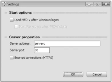
After the MED-V Client components have been installed on personal computers 1, 2, and 3, they will need to be configured properly to work with the MED-V solution. The steps for configuring MED-V Client components are listed below. The MED-V Client Settings screen is shown in Figure 16.5.PC1 — Windows Vista MED-V Client and Management Console
The process of configuring the Windows Vista MED-V Client and Management Console includes the following steps:
1. Launch the MED-V Client software.
2. Right-click the MED-V icon on the system tray and select Settings.
3. Under Start Options, verify that the Load Med-V After Windows Logon check box and Start Workspace When Med-V Starts check box have been selected.
4. Under Server Properties, enter the appropriate Server Address and Port data. In this instance, the server would be ServerC. Select Encrypt Connections (HTTPS) if applicable.
PREPARING, DEPLOYING, AND UPDATING MED-V IMAGES AND WORKSPACES 493
Figure 16.5 MED-V Client settings
PC2 — Windows Vista MED-V Client
The steps for configuring the Windows Vista MED-V Client are the same as those performed on PC1. Please refer to the MED-V Client configuration instructions for PC1.
PC3 — Windows XP MED-V Client
The steps for configuring the Windows XP MED-V Client are the same as those performed on PC1. Please refer to the MED-V Client configuration instructions for PC1.
Preparing, Deploying, and Updating MED-V Images and
Workspaces
Now that the MED-V solution components have been installed and configured on the required servers and clients, the environment is ready to create and prepare VPC images, create test MED-V Workspace images, and deploy MED-V workspace images. The following sections pro-vide an overview of this process.
Create and Prepare a VPC Image for MED-V
A MED-V Workspace image consists of a Virtual PC (VPC) virtual machine that has been prop-erly prepared for the MED-V environment. The preparation consists of the following steps:
1. Create the virtual machine image with the Microsoft Virtual PC Console. As mentioned before, Microsoft Virtual PC 2007 SP1 with KB 958162 update is required. In this instance, we will use VM configuration settings of 512 MB memory and hard disk size of 65 GB.
2. Start the new virtual machine and install Windows XP SP2/SP3 or Windows 2000 SP4 in the VPC virtual machine. Note that the MED-V solution requires this Windows client oper-ating system to use a Volume License Key (VLK).
3. Install the VPC Virtual Machine Additions on the virtual machine.
a. On the Virtual PC VM Console menu, select ActionInstall Or Update Virtual Machine Additions.
b. On the Would You Like To Install Or Update The Virtual Machine Additions Now? window, click Continue.
c. On the Welcome To Setup For Virtual Machine Additions window, click Next, and the installation process will begin.
d. On the Setup Completed window, click Finish and Yes to restart Windows.
4. Install Microsoft .NET Framework 2.0 SP1 on the virtual machine. Microsoft .NET Frame-work 2.0 SP 1 can be downloaded fromwww.microsoft.com/downloads.
5. Install any additional software, such as utilities and applications.
6. Install MED-V Workspace software, and run the VM Prerequisites tool on the virtual machine.
a. Run the MED-V installation fileMED-V_Workspace_1.0.72.msiin the virtual machine. b. On the Welcome To The InstallShield Wizard For MED-V screen, click Next.
c. Review the License Agreement screen, and if you accept the terms, select I Accept The Terms In The Agreement, and click Next.
d. On the Ready To Install Program screen, click Install.
e. On the InstallShield Wizard Completed screen, select the check box for launching the VM Prerequisites tool and click Finish. Note that you can also run this tool from Start
All ProgramsMED-VMED-V VM Prerequisites Wizard.
f. Review the MED-V VM Prerequisite Wizard Welcome screen, and click Next. g. Review the Windows Settings screen, accept the default settings, and click Next. h. Review the Internet Explorer screen, accept the default settings, and click Next.
i. Review the Windows Services screen, accept the default settings, and click Next. j. On the Windows Auto Logon screen, select the check box for Enable Windows Auto
Logon, enter a valid username and password, and click Apply.
k. On the MED-V pop-up screen, when asked if you want to apply all the changes now, click Yes.
7. Review the Summary screen, and click Finish.
8. Test the newly created VPC image to ensure that the virtual machine, Windows operating system, and applications are running properly.
9. The next step is to run the System Preparation Utility (Sysprep) on the Windows operating system. In this instance we will follow the steps below. For more information on how to use Sysprep, please refer totechnet.microsoft.com.
a. Create a directory calledSysprepon the root directory of the Windows XP VM. b. From the Windows XP media orwww.microsoft.com/downloads, copy theDeploy
Cabinetfile to the VM. This file is located on the Windows XP media in the
\support\toolsdirectory.
c. Extract thesetupmgr,sysprep, andsetupclfiles from to thesysprepdirectory. d. Run the extractedsetupmgr(Microsoft Setup Manager Wizard) file. Follow the Setup
Manager Wizard, and create a new answer file, choose Sysprep setup, choose the cor-rect product version, accept the terms of the licensing agreement (only if you agree to
PREPARING, DEPLOYING, AND UPDATING MED-V IMAGES AND WORKSPACES 495
them), enter the name and organization, accept the default display settings, enter the time zone, enter the Volume Licensing Key (VLK) product key, select to auto generate the computer name, enter an administrator password, select network components, enter the workgroup or domain, enter Telephony settings, enter Regional settings, select a language, install printers, and enter additional commands and an identification string if appropriate. Click Finish, and save the answer file by clicking OK. Once Setup Manager is complete, close the Completing Setup Manager window.
e. Run the extractedsysprepfile. Follow the Sysprep wizard, clicking OK to run Sysprep, selecting to use Mini-Setup, and clicking the Reseal button. Click OK to regenerate SIDs. The Sysprep process will begin and when completed will shut down Windows and stop the VM.
Creating a MED-V Image
After the VPC virtual machine has been created and prepared for the MED-V environment, you can upload it into the Image Repository. The process for creating a test image, packing the tested image, and uploading or extracting the image is described next.
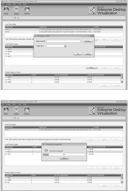
The first step to adding our newly created VPC virtual machine into the MED-V environ-ment is to create a test image. The steps for creating a test image are as follows:
Creating a Test Image
1. From PC1 client launch the MED-V Management Console from StartAll Programs
MED-VMED-V Management or from the MED-V Management desktop shortcut.
2. Select the Images icon.
3. Under Local Test Images, select New.
4. On the Test Image Creation dialog box, click Browse, select the Windows VM Settings file for the Windows XP image we just created, and click Open. Enter an image name and click OK. The Image Creation dialog box is shown in Figure 16.6. The process will create a new directory on the Management Console’s local hard disk atC:\MED-V_Images\imagename. The directory includes aGlobalImageDataXML file andTestdirectory. TheTest direc-tory includes anImageStateXML file and the image’s Virtual Machine Settings file. After a test image has been created and tested, you can further prepare the image by pack-ing it. The packpack-ing process compresses the image and stores it on the Management Console’s local hard disk atC:\MED-V_Images\PackedImages. Two packed image files are created: the Kidaro Compressed Machine (imagename.ckm) file and the Index file (imagename.ckm.index) file.
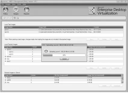
Packing an Image
1. In the MED-V Management Console, select the Images icon.
2. Under Local Test Images, select the test image we created earlier and click Pack. The packing process will begin with the Packing The Image Files screen displaying the process and status, as shown in Figure 16.7. This process may take several minutes to complete.
Once a MED-V image has been packed, it can be uploaded. The uploading process copies the packed image files to the Repository Server, where it is available for client deployments.
Uploading a Packed Image
1. In the MED-V Management Console, select the Images icon.
2. Under Local Packed Images, select the image we just packed and click Upload.
3. The action will begin with the Uploading screen displaying the process and status, as shown in Figure 16.8.
Figure 16.6 Test Image Creation dialog box
Figure 16.7
Packing The Image Files screen
PREPARING, DEPLOYING, AND UPDATING MED-V IMAGES AND WORKSPACES 497
Figure 16.8 Uploading the image
Creating a MED-V Workspace
The process to create a MED-V Workspace requires creating the Workspace in the MED-V Management Console and configuring settings in eight areas: General, Virtual Machine, Deployment, Applications, Web, VM Setup, Network, and Performance. The process for creating and configuring a MED-V Workspace is provided below:
1. Launch the MED-V Management Console.
2. Select the Policy icon.
3. Under the Workspaces pane on the right side of the console, click the Add button to create a new Workspace, which we will configure in the following steps.
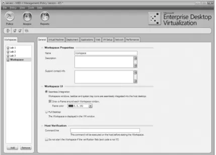
4. Configure the General settings. The General configuration settings include areas for defin-ing Workspace Properties, Workspace UI, and Host Verification.
a. Click the General tab.
b. Under the Workspace Properties settings, enter the name of the Workspace, its descrip-tion, and support contact information. In this instance, we will accept the default name of Workspace.
c. For the Workspace UI settings, you can choose Seamless Integration or Full Desktop. Accept the default settings of Seamless Integration and Draw A Frame Around Each Workspace Window.
d. For Host Verification, accept the default settings, leaving the command line blank. Don’t select the check box for not starting the Workspace if the verification fails. This setting enables a command to be run and verified on the host prior to starting the Workspace.
Figure 16.9 General tab
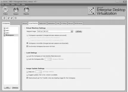
5. Configure the Virtual Machine settings. The Virtual Machine configuration settings include areas for defining Virtual Machine Settings, Lock Settings, and Image Update Settings. a. Click the Virtual Machine tab.
b. For the Virtual Machine Settings, select the Windows XP image that we created in an earlier step as the Assigned Image. Select the Workspace Is Revertible radio button. A revertible VM is a MED-V Workspace image that returns to its original state after each session. Leave the Synchronize Workspace Time Zone With Host option at its default setting of being selected.
A Workspace can also be configured to be persistent. A persistent VM is a MED-V Workspace image that saves its state after each session. Other options for a persistent Workspace include shutting down the VM when stopping the Workspace, logging into Windows, running in the VM, and using MED-V credentials to support Single Sign-on (SSO).
c. Under Lock Settings, accept the defaults of not enabling the Workspace to be locked during host standby or hibernation and the related option to lock the Workspace after a specific amount of idle time.
d. Accept the default Image Update Settings of not enabling the Keep Only (#) Old Image Versions and Suggest Update When A New Version Is Available. Also accept the default setting of enabling Clients Should Use Trim Transfer When Downloading Images For This Workspace. Trim Transfer is a MED-V technology that optimizes the process of deploying or updating a Workspace image to a client. Prior to MED-V deploying an image to a client, Trim Transfer indexes the client hard drive and compares this data to the Workspace image, looking for duplicated operating system and application data. Once this process is complete, Trim Transfer will transfer only image data from the Repository Server that doesn’t already reside on the client hard disk, minimizing the amount of data transferred, optimizing network bandwidth, and reducing deployment and update time.
PREPARING, DEPLOYING, AND UPDATING MED-V IMAGES AND WORKSPACES 499
Figure 16.10 Virtual Machine tab
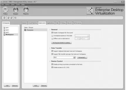
6. Configure the Deployment settings. The Deployment configuration settings include areas for defining which users and groups have access to the Workspace, Workspace expiration data, offline restriction, data transfer behavior, and device control.
a. Click the Deployment tab.
b. For the General settings, select Enable Workspace For ‘Everyone.’ You can add or remove users and groups by clicking the Add or Remove button under the Users / Groups pane on the left. Leave the check boxes for Workspace expiration and offline work restriction unchecked.
c. For the Data Transfer settings, select the check boxes for Support Clipboard Between Host And Workspace and Support File Transfer Between The Host And Workspace. Note that we are enabling these settings for the purpose of evaluating these fea-tures in a MED-V test environment. If you are deploying MED-V in a production environment, configure these settings based on your organization’s guidelines and policies.
d. For the Device Control settings, select the check box for Enable Printing To Printers Connected To The Host and Enable Access To CD / DVD. We are enabling these set-tings for the purpose of evaluating these features in a MED-V test environment. If you are deploying MED-V in a production environment, configure these settings based on your organization’s guidelines and policies.
The Deployment tab is shown in Figure 16.11.
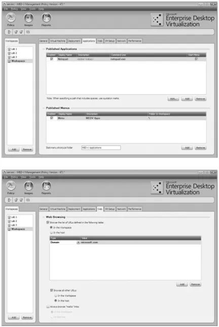
7. Configure the Applications settings. The Applications configuration settings include areas for defining which applications and menus that exist on the image are published for this MED-V Workspace.
a. Click the Applications tab.
b. Add published applications. Click the Add button under the Published Applications area and type Notepad in the Description field andnotepad.exein the Command Line field. You can enter other applications in a similar manner.
Figure 16.11 Deployment tab
c. Enter the appropriate menus in the Published Menus section. Click the Add button under the Published Menus area and type Accessories for the Description and Folder In Workspace fields. Note that you can include all folders by entering a backslash (\) in the Folder In Workspace field. Leave the Start Menu Shortcuts Folder field with the default entry of MED-V Applications.
Application shortcuts can also be created for MED-V Workspace published applications on the host desktop by using the following command:"drive
letter:\program files\microsoft enterprise desktop virtualization\manager\
kidarocommands.exe" /run "published application name" "MED-V Workspace
name". You can find more information about the use of Kidaro commands by typing"drive letter:\program files\microsoft enterprise desktop virtualization\manager\kidarocommands.exe" /help.
The Applications tab is shown in Figure 16.12.
8. Configure the Web settings. The Web configuration settings include areas for defining web-browsing behavior for the Workspace and host.
a. Click the Web tab.
b. For the Web Browsing settings, select the check box Browse The List Of URLs Defined In The Following Table. In The Workspace will be selected by default. Click the Add button located in the lower-right side of the Web Browsing area. We will leave the Type field with the default setting of Domain. Note that this field can be set to Domain Suffix, IP Suffix, or All Local Addresses. Enter www.microsoft.com in the Value field.
c. Select the check box Browse All Other URLs and the radio button In The Host. d. Leave the check box Always Browse ‘‘Mailto’’ Links blank.
PREPARING, DEPLOYING, AND UPDATING MED-V IMAGES AND WORKSPACES 501
Figure 16.12 Applications tab
Figure 16.13 Web tab
9. Configure the VM Setup settings. The VM Setup configuration settings include areas for defining Persistent VM Setup, Revertible VM Setup, VM Computer Name Pattern, and Script Actions. For this test environment, we will set up the MED-V Workspace image for a revertible setup. This setup process further configures the Workspace image and is run once on the initial deployment after the Sysprep mini-setup is completed.
a. Click the VMSetup tab.
b. Under Revertible VM Setup, select the check box Rename The VM Based On The Com-puter Name Pattern.
c. For the VM Computer Name Pattern settings, click the Insert Variable list box and select Host Name. Other choices include User Name, Domain Name, Workspace Name, and Virtual Machine Name.
Note that if our MED-V Workspace image was configured to be persistent, we would have the option to run a script as part of the MED-V VM setup process. To create a VM setup script, select Run VM Setup and click the Script Editor button. The script editor includes prebuilt scripts to restart Windows, join a domain, check network connectivity, run a command from a command line, rename a computer, and disable auto logon. To add and configure a prebuilt script action, click the Add button under the Script Actions Pane. Once the script is complete, click OK.
The VM Setup tab is shown in Figure 16.14. Figure 16.14
VM Setup tab
10. Configure the Network settings. The Network configuration settings include areas for defining TCP/IP Properties and DNS Options.
a. Click the Network tab.
b. Accept the default TCPIP Properties setting Use Host’s IP Address (NAT). If the Workspace requires its own IP address, you can enable this by selecting Use Different IP Address Than Host (Bridge).
c. Accept the default DNS Options settings to use the host’s DNS address. Options are also available for changing the configured DNS setting in the image or using a specific DNS address. Also accept the default setting for Assign DNS Suffixes, which is Append Host Suffixes.
The Network tab is shown in Figure 16.15.
11. Configure the Performance setting. This setting defines a specific amount of memory that will be available to the MED-V Workspace based on the host’s memory configuration.
PREPARING, DEPLOYING, AND UPDATING MED-V IMAGES AND WORKSPACES 503
Note that this is a valuable setting for legacy applications that require a specific amount of memory to run.
a. Click the Performance tab.
b. Enter the appropriate VM Memory Allocation settings. The Performance tab is shown in Figure 16.16.
12. After the Workspace has been created and configured properly, in the top menu bar select PolicyCommit to save your changes.
Figure 16.15 Network tab
Figure 16.16 Performance tab
Testing a Med-V Workspace
After you’ve created a Workspace in the MED-V Management console, you can test it on the local Management Console workstation prior to deploying it to users. The steps for this process follow:
1. Launch the MED-V Client on the Management Console workstation.
2. Enter the administrator username and password on the Start Workspace screen.
3. On the Workspace selection screen, select the Workspace we just created. A Confirm Running Test dialog box will display, as shown in Figure 16.17. Click the Use Test Image button.
Figure 16.17 Confirm Running Test dialog box
4. The selected test image will start. You can now test the workspace on the workstation.
5. If you need to make Workspace setting changes to the test Workspace, such as for behavior or memory, stop the Workspace and launch the MED-V Management Console to reconfig-ure the test Workspace, save your changes, and test again.
Deploying a MED-V Workspace
A Med-V Workspace can be deployed to a user’s personal computer in one of three ways. These methods include using the MED-V infrastructure, Electronic Software Distribution (ESD), and removable media (DVD or USB). Let’s review each type of deployment and its process.
MED-V Infrastructure Deployment
A MED-V Workspace can be deployed to user’s personal computers using the MED-V Management Server, the Image Repository, and Client software. All of these MED-V infrastruc-ture components must be installed and configured prior to the deployment of the Workspace,
PREPARING, DEPLOYING, AND UPDATING MED-V IMAGES AND WORKSPACES 505
including the installation of the MED-V Client software and prerequisite software. The process for deploying a MED-V Workspace using MED-V Infrastructure is provided in the following steps.
1. Create the MED-V Workspace and upload the packed image to the repository using the MED-V Management Console using the steps above.
2. Launch the MED-V Client software on the personal computer targeted for the Workspace deployment.
3. Provide the appropriate username and password on the Start Workspace screen.
4. If the user has been assigned to more than one Workspace, select the desired Workspace from the list. The Workspace Download process screen will display and carry out the fol-lowing steps:
a. Index the local hard disk. b. Download the image.
5. The Starting Workspace screen will display the progress, as shown in Figure 16.18, and will disappear once the Workstation has started properly. A Windows Notification icon will be displayed on the taskbar. The MED-V Workspace is now ready to use.
Figure 16.18 Starting Workspace screen
Electronic Software Distribution Deployment
An Electronic Software Distribution tool such as Microsoft System Center Configuration Manager can also be used to initially deploy a MED-V Workspace. This method may be appropriate if an organization already has an ESD infrastructure in place and uses it as their standard method for distributing software. An advantage of using ESD in a WAN environment is the initial MED-V Workspace image deployment and the ability to distribute the image once to a remote site and then transfer the image locally to prestaged directories on each client. A disadvantage of ESD is not being able to use MED-V’s Trim Transfer technology. The process for deploying a MED-V Workspace using Electronic Software Distribution is provided in the following steps.
1. Create the MED-V Workspace, and upload the packed image to the repository using the MED-V Management Console. You can skip this step if you have already created the MED-V Workspace and image.
2. Download the image to the desired Management Console workstation using the MED-V Management Console. The image files will be downloaded to the
C:\MED-V_Images\PackedImages\imagenamedirectory on the local hard disk of the Management Console. You can skip this step if you have already downloaded the MED-V Workspace and image.
3. Create an Electronic Software Distribution package that includes the two MED-V packed image files (Compressed Machine file and Index file) that were downloaded.
4. Distribute the packed image files to the targeted user’s personal computer’s hard disk in the prestaged images directory located atC:\Med-V Images\PrestagedImages.
5. Launch the MED-V Client software on the personal computer targeted for the Workspace deployment.
6. Provide the appropriate username and password on the Start Workspace screen.
7. If the user has more than one Workspace assigned, choose the desired Workspace.
8. The Starting Workspace screen will display the progress and disappear once the Worksta-tion has started properly. A Windows NotificaWorksta-tion icon will be displayed on the taskbar. The MED-V Workspace is now ready to use.
Removable Media Deployment
Removable media such as a DVD or USB storage device can also be used to initially deploy a MED-V Workspace. The process for deploying a MED-V Workspace using removable media is provided in the following steps:
1. Create the MED-V Workspace, and upload the packed image to the repository using the MED-V Management Console. You can skip this step if you have already created the MED-V Workspace and image.
2. Download the image to the desired Management Console workstation using the MED-V Management Console. The image files will be downloaded toC:\MED-V_Images\ PackedImages\imagenamedirectory on the local hard disk of the Management Console. You can skip this step if you have already downloaded the MED-V Workspace and image.
3. To prepare for the Packaging Wizard deployment package process, create a local or network directory with separate subdirectories for the MED-V client, Virtual PC, and .NET Framework installation files, and copy the associated setup files into these directories. The Packaging Wizard will ask for the location of these installation files during this process.
4. On the MED-V Management Console top menu bar, select ToolsPackaging Wizard.
5. On the Packaging Wizard Deployment Package screen, click Next.
6. On the Workspace Image screen, mark the check box to include the image in the package. Select the image we just downloaded and click Next.
7. On the MED-V Installation Settings screen, select the path where we located the MED-V installation files, enter the MED-V server address and port, select Install MED-V Using Default Installation Settings if appropriate, and click Next.
MANAGING THE MED-V SOLUTION 507
8. On the Additional Installations screen, select the appropriate check boxes and installation path for Virtual PC 2007 SP1, Virtual PC QFE, and .NET Framework 2.0, and click Next.
9. On the Finalize screen, enter the path for the package destination and package name, and click Finish.
10. Copy the contents of the MED-V deployment package to the removable media (DVD or USB storage device).
a. On the personal computer targeted for the Workspace deployment, insert the DVD or USB storage device that has the deployment package files that we previously copied. b. Open the removable media device, and launch theMedvAutorun.exeapplication. The
MED-V screen will appear, asking if you would like to install the MED-V package now. The Installer screen will be also be displayed and will provide progress information for the installation of Virtual PC 2007 SP1, Virtual PC 2007 SP1 Update, MED-V Client, and the importing of the Workspace image. At the end of the process, the MED-V Installer window will display a message saying that MED-V was successfully installed. c. The MED-V Workspace is now ready to use.
Managing the MED-V Solution
The Microsoft MED-V solution can be managed using Microsoft management tools that are included in MED-V, Windows Server 2008, and System Center. The MED-V Management and Server Manager tools are discussed below, along with a mapping of the tools for each server and client in the solution.
The MED-V solution or instance can be managed by using Server Manager/IIS Manager, MED-V Server Configuration Manager, and MED-V Management Console.
Server Manager, IIS Manager
Server Manager is used to manage the Web Server (IIS) role that supports the MED-V Image Repository solution. The IIS Main Summary page offers a number of useful tools and informa-tion for managing your MED-V environment. The main page includes System Services, Best Practice Analyzer, Role Services, and Resources And Support. You can access this tool through Server Manager, by selecting the IIS role or by using IIS Manager.
MED-V Server Configuration Manager
The MED-V Server Configuration Manager runs on the MED-V Server and is used to initially configure the MED-V Server environment settings. These settings include client connections, location for storing images in the repository, management permissions, and database settings. If you need to change any of these configuration settings, you would use the MED-V Server Configuration Manager tool.
MED-V Management Console
The MED-V Management Console is the primary management tool for the MED-V and sup-ports the life cycle of the Workspace images. It provides management of MED-V Workspaces, images, and reports. The Management tool supports the creation and configuration of MED-V Workspaces, image creation, and deployment and generation of status, activity, and error reports.
MED-V Logs and Events
You can review MED-V logs and events using the MED-V Management Console reports to view the status, activity, and error log information. This information can be viewed within the Management Console or exported into Microsoft Excel. Figure 16.19 show the MED-V Diagnostic tool.
Figure 16.19 MED-V client activity report
In addition, the MED-V Client software includes MED-V Diagnostics, which can gather com-prehensive log information related to that MED-V client. You can access this tool through the Program menu under MED-V ManagementToolsMED-V Diagnostic Tool or by selecting the MED-V Notification icon under Help.
MED-V Client Tool
The MED-V Client tool is used to start MED-V, open Help, run Diagnostics, configure the MED-V client Start options and Server Connection properties, and start or stop a Workspace. You can access this tool by selecting the MED-V Notification icon.
MED-V Diagnostics
The MED-V Diagnostics tool is used to review system, policy, Workspace, and image store information on the MED-V client. In addition, you can use the tool to gather diagnostic logs, update a policy, enable diagnostic mode, and browse the local image store. A screen shot of the MED-V Diagnostics tool is provided in Figure 16.20.
ServerA: MED-V Image Repository Server
The MED-V Solution Management tools required to manage the MED-V Image Repository Server includes Server Manager\IIS Manager, MED-V Server Configuration Manager, and the MED-V Management Console.
MANAGING THE MED-V SOLUTION 509
Figure 16.20 MED-V Diagnostics tool
ServerB: MED-V Database Server
The MED-V Solution Management tools required to manage the MED-V Database Server includes SQL Server Configuration Manager and Management Studio, MED-V Server Configuration Manager, and the MED-V Management Console.
ServerC: MED-V Management Server
The MED-V Solution Management tools required to manage the MED-V Management Server includes Server Manager, SQL Server Configuration Manager and Management Studio, MED-V Server Configuration Manager, and the MED-V Management Console.
PC1 — Windows Vista MED-V Client and Management Console
The MED-V Solution Management tools required to manage the Windows Vista personal com-puter include the MED-V Client tool and MED-V Diagnostics.
PC2 — Windows Vista SP1 MED-V Client
The MED-V Solution Management tools required to manage the Windows Vista personal com-puter include the MED-V Client tool and MED-V Diagnostics.