O R I G I N A L R E S E A R C H
Open Access
Comparative study of three types of
controllers for DFIG in wind energy
conversion system
Saïd Boubzizi
1,2*, Hafedh Abid
1, Ahmed El hajjaji
2and Mohamed Chaabane
1Abstract
This paper presents an enhanced control strategy for Wind Energy Conversion System (WECS) using Doubly-Fed Induction Generator (DFIG). A robust Super-Twisting (STW) sliding mode control for variable speed wind turbine is developed to produce the optimal aerodynamic torque and improve the dynamic performance of the WECS. The electromagnetic torque of the DFIG is directly tracked using the proposed control to achieve maximum power extraction. The performance and the effectiveness of the STW control strategy are compared to conventional Sliding Mode (SM) and Proportional-Integral (PI) controllers. The proposed STW algorithm shows interesting features in terms of chattering reduction, finite convergence time and robustness against parameters variations and system disturbances.
Keywords:Wind turbine (WT), Doubly-fed induction generator (DFIG), Power generation, STW (super-twisting), Second order sliding mode control (SOSMC), PI controller
1 Introduction
Over the last decade, wind energy has taken an increas-ingly important place in the field of electric energy gen-eration. This kind of energy source is developed due to the global growing of electricity demand and the trend towards renewable and non-polluting energy sources in the world [1]. Indeed, in wind energy conversion system (WECS), the maximum wind power could be extracted when the tip-speed-ratio of the turbine is maintained at its optimum value for different wind speed patterns [2]. Thus, it is necessary to develop more advanced control strategies for WECS. To this end, several control methods have been designed and implemented for wind energy generation such as, vector control which is based on voltage and flux oriented vector using the d-q rotat-ing frame to decouple the active and reactive power, [3,
4]. In fact, this strategy is sensible to parameters varia-tions of the system such as resistance and inductance variations. To overcome this problem, direct torque
control (DTC) has been introduced by [5, 6] to directly control generator torque and stator flux using a prede-fined lookup table based on the estimation of the stator flux and electromagnetic torque. Direct power control (DPC) proposed in [7], has used the same concept of the DTC method. DPC control strategy is based on decoup-ling and direct control of reactive and active power [8]. In fact, the non-linear behaviors of mechanical and elec-trical parts of WECS as well as variations of electro-mechanical parameters represent crucial problems [9]. In addition, wind turbine (WT) works under high wind speed variations, which makes its control a serious chal-lenge [10]. As result, several nonlinear control tech-niques have been developed in the literature for WT, such as fuzzy logic [11], neural networks [12], and high-order sliding mode control [13].
Currently, most WECS use Double feed induction generator (DFIG). This is due to many advantages such as variable speed operation of the generator (± 30% around the synchronous speed), decoupling between ac-tive and reacac-tive powers, maximization of energy gener-ation and competitive price [1]. But, DFIG is subjected to many constraints, such as the effects of parametric variations and the disturbance of the wind speed, which
* Correspondence:[email protected]
1Lab-STA Laboratory, National Engineering School of Sfax, Route de la Soukra, 3029 Sfax, Tunisia
2MIS Laboratory, University of Picardie Jules Verne, 33, Rue Saint-Leu, 80039 Amiens, France
could deviate the system from its optimal operation point. Many control techniques of the DFIG have been presented with different control schemes. The conven-tional Proporconven-tional-Integral (PI) controller, although widely used in many control applications [14], requires adjustment for every change in reference patterns. An-other main disadvantage of this controller is its sensibil-ity to external disturbances and parameters variations. Because of the frequent uncertainty in wind speed varia-tions, this type of conventional controller fails to give quality power generation and tracking references given by an MPPT. Predictive control based on rotor voltage and stator power equations for direct power control, is proposed in [15,16]. Nevertheless, the calculated output reactive and active power which depend on the gener-ator parameters as well as the time calculation, are the main drawbacks of this method [17]. In addition, in-ternal uncertainties and exin-ternal disturbances produce serious oscillations of the WECS. To ensure the robust-ness of the system against parametric variations and ex-ternal disturbances, the authors in [18, 19] have introduced sliding mode control (SMC). In fact, SMC could achieve active and reactive power tracking and im-prove the dynamic.
behaviour of the WT [20]. Second order sliding mode control (SOSMC) could guarantee the same perform-ance of classical SMC with its ability to overcome the chattering problem [21]. The main contribution of this paper, which deals with WECS based on DFIG, consists in developed and compared the performances and the robustness of three types of controllers for the DFIG with aerodynamic torque estimation. In this paper, a high order SMC is used to improve the dynamic perfor-mances of WECS by producing the required electromag-netic torque under different wind speed patterns. The desired DFIG torque is directly tracked to achieve max-imum power extraction. In order to prove the robust-ness performance of the proposed controller, its dynamic behaviour is compared with the conventional Sliding Mode (SM) and Proportional-Integral (PI) con-trollers under high wind speed variations. The simula-tion results show that high order SMC is an interesting method to control WECS based on DFIG.
This paper is organized as follow: Section 2 recalls a short overview of first order sliding mode control and second order sliding mode control. In the Section3, we present the structure of wind energy conversion system then the modelling of turbine and the double feed in-duction generator. In the first part of Section 4, we present the estimation of the aerodynamic torque. In the second part of Section4, we describe the control of the aerodynamic torque. In Section 5, we interest to the control of DFIG. In this context, we compare three types of controllers such as PI, sliding mode control and
second order sliding mode control. Finally, Section 6
shows the simulation results of the proposed system.
2 Sliding mode control strategy 2.1 First order sliding mode control
Sliding mode control is a powerful nonlinear control, which has been analyzed by many researchers. The slid-ing mode control law includes two main parts [22]:
V¼VeqþVn ð1Þ
Veq is called equivalent control and Vn is known as switching control signal.
We consider the following sliding surface, [23]:
S Xð Þ ¼ d dtþλ
n−1
e ð2Þ
where,e=Xd−Xis the error of the signal to be adjusted,
λis a positive coefficient andnis the system order. The main target in this methodology is to keepS(X) = 0 andS_ðXÞ ¼0.
The reaching condition is given by the following equation:
S Xð ÞS X_ð Þ≤0 ð3Þ
2.2 Second order sliding mode control
As well known, classical sliding mode method generates undesirable chattering effect which can be harmful for the system, SOSMC can only attenuate this problem. Therefore, Super-Twisting (STW) strategy is nowadays preferable over the classical siding mode, since it elimi-nates the chattering phenomenon.
Let us consider the following nonlinear system
_
S Xð Þ ¼ f tð;SÞ þu ð4Þ
where,f(t,S)is an unknown bounded perturbation term, with |f(t,S)| <δ|S|1/2for some constantδ> 0.
The STW sliding mode control for perturbation and chattering elimination is given by the next algorithm:
u¼v−a1j jS1=2sgnð ÞS
_
v¼−a2sgnð ÞS
ð5Þ
where,a1anda2are fixed gains.
From Eqs. (4) and (5), we can deduce
_
S¼vþf tð;SÞ−a1j jS1=2 sgnð ÞS
_
v¼−a2sgnð ÞS
ð6Þ
V¼2a2j j þS
1 2v
2þ1
2 a1j jS
1=2
sgnð ÞS −v
2
ð7Þ
To guaranteeV_ <0 , the controller gains must satisfy the following conditions, [24].
a1>2δ; a2>a1
5δa1þ4δ2
2ða1−2δÞ
The controller gains a1 and a2 are designed in order to fulfill the previous conditions and to ensure low con-tent of high frequency components in the control. In-deed, a high gains values can lead to high chattering effects and poor performance.
3 System description
The most popular configurations of Wind Energy Con-version Systems (WECS) use the DFIG, as shown in Fig. 1. In this configuration, the wind turbine rotates with variable wind speed. It converts first the kinetic power into mechanical power then into electrical power through the generator (DFIG).
The expression of the aerodynamic power is given by the following Eq. [8]:
Pa ¼
1 2πR
2ρC
pð Þλ ν3 ð8Þ
where, ν, R, Cp(λ) denotes respectively the wind speed,
the radius, and the power coefficient of the turbine. The tip-speed ratio is defined as follows:
λ¼RΩrν ð9Þ
The extraction of aerodynamic power depends mainly on the available wind speed, the characteristic power curve (Cp) and the capacity of the wind turbine to
re-spond to the changes in wind speed, as shown in Fig.2. The generator is coupled to the turbine through a gearbox whose ratio is given by the following equation:
ng¼ΩrΩ ð10Þ
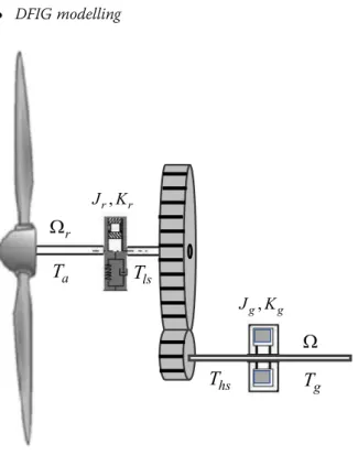
The overall mechanical dynamics of WECS brought back to the turbine, which is represented by Fig. 3, can be expressed by the following equation [25]:
JΩr_ ¼Ta−KΩr−Tg ð11Þ
with
J ¼ Jrþn2gJg
K¼Krþn2gKg
Tg¼ngTem 8
<
: .
where,J,KandTemrespectively represent the overall
in-ertia of WECS, the overall external damping of WECS and the electromagnetic torque of the generator.
DFIG modelling
Fig. 1WECS configuration based on DFIG
Fig. 2WT power coefficient
The electrical model of the DFIG in the d-q frame linked to the stator rotating field is given by the system (12), [26]:
Vsd¼RsIsdþϕ_sd−ωsϕsq
Vsq¼RsIsqþϕ_sqþωsϕsd
Vrd¼RrIrdþϕ_rd−ωϕrq
Vrq¼RrIrqþϕ_rqþωϕrd 8
> > > < > > > :
ð12Þ
The flux linkages are given by system (13):
ϕsd¼LsIsdþMIrd
ϕsq¼LsIsqþMIrq
ϕrd¼LrIrdþMIsd
ϕrq¼LrIrqþMIsq 8
> > > > < > > > > :
ð13Þ
The electromagnetic torque, active and reactive power developed by the DFIG can be expressed the following equations:
Tem¼np
M Lsð
Irdϕsq−IrqϕsdÞ
P¼VsdIsdþVsqIsq
Q¼VsqIsd−VsdIsq
ð14Þ
By using the field oriented control approach and neglecting stator resistance, we obtain, [27]:
ϕsd¼ϕs¼cte
ϕsq¼0
_
ϕsd¼0
Vsd¼0
Vs¼Vsq¼ωsϕsd 8
> > > > < > > > > :
ð15Þ
and
_ Ird¼
1 σLrð
Vrd−RrIrdþsωsσLrIrq−
M Ls
_ ϕsdÞ
_ Irq¼
1 σLrð
Vrq−RrIrq−sωsσLrIrd−sωs
M LsϕsdÞ 8
> > < > >
: ð16Þ
Then, the active and reactive powers can be expressed as:
P¼VsqIsq
Q¼VsqIsd
ð17Þ
The expression of electromagnetic torque becomes:
Tem¼keIrq ð18Þ
with,ke¼−np
M Lsϕsd
.
4 Control of the turbine
In order to extract the wind energy, while ensuring the safety, the WT must operate in the second or third zone, as shown in Fig.4.
The machine starts to work when the mechanical speed exceeds a certain speed νcut−in. The main
operat-ing area can be distoperat-inguished as follows:
Zone 1: In this area, the WT is unable to generate any power.
Zone 2: This zone is limited byνcut−inandνrated. In
this area, the WT can operate with its maximum power coefficientCpmax.
Zone 3: The WT produces the rated power. Beyond νcut_off, an emergency device is activated to avoid
damaging the system.
To ensure maximum efficiency of the WT, the power coefficient must be maintained at its maximum value in order to reach the optimal torque, which is given by the following equation:
Topt ¼koptΩ2r ð19Þ
where,kopt ¼
1 2R
5πρCpmax
λ3 opt
.
The major problem of standard law is mainly the de-termination with accuracy the value of kopt since λopt
change significantly over time. To achieve WT power ef-ficiency maximization, rotor speed should track the ref-erence given by the optimum speed ratio, under variable wind speed and unknown aerodynamic torque. The wind speed variation would lead to aerodynamic power fluctu-ation and high mechanical effort, which results in less energy capture and poor performance in terms of active power generation. In the following, a second order slid-ing mode control (SOSMC) with aerodynamic torque observer is proposed.
4.1 Torque estimation
Aerodynamic torqueTa(t)in Eq. (11), depends on the
knowledge of the torque coefficient which is a difficult task to be achieved and not always available [28].
In this sense, an aerodynamic torque T_aðtÞ observer based on STW algorithm is used, [21]:
_ Ω _ r¼ T _ a J − K
JΩr− Tg
J −a1
j
Ω_
r−Ωr
j
1=2sgn Ω_r−Ωr !
_
T
_
a ¼ −
a2
2JsgnðΩ
_
r−ΩrÞ 8 > > > < > > > :
ð20Þ
wherea1anda2are fixed gains.
The observation error is defined as follows:
σ1¼Ω
_
r−Ωr ð21Þ
We assume that term Ta(t) and its derivative are
bounded with a known boundary which satisfies the fol-lowing condition:
j
T_aðtÞj
<JΨ1 ð22Þwhere,Ψ1is a positive constant.
Thus, we have
_
σ1¼−a1jσ1j1=2sgnðσ1Þ þη
_
η¼−a2
2sgnðσ1Þ−
_ Ta J 8 > < >
: ð23Þ
where,a1anda2verify the following inequalities:
a1>Ψ1
a2>
ffiffiffiffiffiffiffiffiffiffiffiffiffiffiffiffiffiffiffiffiffiffiffiffi
4Ψ1a1þΨ1 a1−Ψ1 r
8 <
: ð24Þ
Thus, we can guarantee the convergence ofσ1and its derivative to zero in a finite timetF..
4.2 Aerodynamic torque control
In this section, our control objective is to achieve maximum power extraction while maintaining the se-curity regime of the WECS, as illustrated in Fig. 4 by converging T_a to Topt. We consider the following
tracking error:
σ2¼Topt−T
_
a ð25Þ
The derivative of Eq. (25) is:
_
σ2¼2koptΩr
J T
_
a−KΩr−Tg
−T__a ð26Þ
Then, we define the following functions:
A¼2koptΩr
J
B¼2koptΩr
J
ð
T_
a−KΩr
Þ
−T__ a 8 > > < > > : ð 27Þ
We assume that B(Ωr,t) is bounded, B(Ωr,t)≺Ψ2 whereΨ2is a positive constant.
Thus, Eq. (26) can be written as follows:
_
σ2¼BðΩr;tÞ−AðΩr;tÞTg ð28Þ
We consider the following STW algorithm based on second order sliding mode approach, given by the fol-lowing equations:
Tg ¼yþb1jσ2j1=2sgnðσ2Þ
_
y¼b2 2sgnðσ2Þ
8 <
: ð29Þ
where gainsb1andb2satisfy the following inequalities:
b1>Ψ2
b2>
ffiffiffiffiffiffiffiffiffiffiffiffiffiffiffiffiffiffiffiffiffiffiffiffiffiffiffiffiffiffiffiffiffiffi
4Ψ2Amax
b1þΨ2
b1−Ψ2 s
0<Amin ≤A≤Amax 8 > > > > < > > > > :
ð30Þ
In this section, we have proposed a robust control strategy of the WT with aerodynamic torque estimation to achieve maximum power extraction. In the next section, we will tackle the control of the electrical part of our system (DFIG).
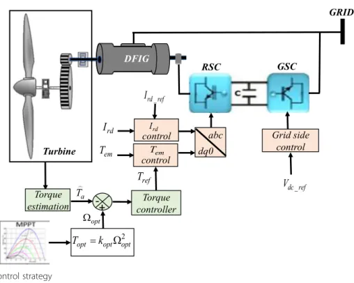
5 Control of the DFIG
In this section, we will interest in the control strategy of the generator, as shown in Fig. 5. In this sense, three types of controllers are developed and compared namely PI, first order SMC and SOSMC, for the DFIG.
Based on Eqs. (13), (15) and (17), the reactive power can be written as follows:
Q¼Vs Ls ϕs−
MIrd
ð Þ ð31Þ
The reference currentIrd, refcan be deduced from Eq.
(31) by keeping the desired reactive powerQ= 0.
Ird;ref ¼ϕs
M¼
Vs
ωsM ð
32Þ
The main objective is to maximize wind power gener-ation by reaching optimal torqueTref.
However, we need to use two controllers. The first is placed in the d axe to keep the reactive power at zero, the second is placed in the q axe to obtain the optimal torque.
Let’s consider the following errors:
σIrd¼Ird−Ird ref
σTem¼Tem−Tref
ð33Þ
5.1 PI controller
The closed-loop control scheme diagrams along the d and q axes are similar. They are given by the fol-lowing figures:
The parameters of the PI controller, Kp and Ki, can
be computed using pole compensation approach. However, it is important to specify that the pole com-pensation is not the only method to compute the PI parameters. The calculation of the controller parame-ters must compensate the most dominant pole of the transfer function.
Let’s consider the case of Ird control as shown
Fig. 6 whose open loop transfer function is written as follows:
GðpÞ ¼Kp p
ð
pþKi
Kp
Þ
Ls
ðLsLr−M2Þ
ð
LsRr
LsLr−M2 þp
Þ
ð34Þ
To eliminate the zero of the transfer function, we choose:
Ki
Kp¼
LsRr
LsLr−M2 ð
35Þ
Then, Eq. (34) becomes:
G pð Þ ¼Kp p
Ls
LsLr−M2
ð36Þ
The closed loop transfer function is expressed by:
H pð Þ ¼ 1
1þτp ð37Þ
with
τ¼LrLs−M2
KpLs
Hence, we can deduce the gains of the PI current regulator:
Kp¼
LsLr−M2
τLs
Ki¼
Rr
τ
8 > > < > >
: ð
38Þ
Similar development can be done forTemcontrol, Fig.7.
The time response of the controlled system is fixed atτ= 5ms. In fact, this value is sufficient in WECS applications.
As we can see, the gains of the controller Kp and Ki,
are directly calculated in function of DFIG parameters, if these parameters are varying in time, the robustness of the whole system can be affected.
Fig. 5WT-DFIG control strategy
5.2 Sliding mode control
In our case, we use two sliding surfaces which are de-fined as follows:
S1¼Ird−Ird−ref
S2¼Tem−Tref
ð39Þ
The derivative of (39):
_
S1¼I_rd−I_rd−ref
_
S2¼T_em−T_ref
ð40Þ
Substituting I_rd and T_em by their expressions in Eq. (16), Eq. (40) can be rewritten as:
_
S1¼
1
σLr
ð
Vrd−RrIrdþsωsσLrIrq−
M Ls
_
ϕsd
Þ
−_Ird−re f
_
S2¼−np
M
σLsLrϕsdð
Vrq−RrIrq−sωsσLrIrdÞ þsωs
M Lsϕsd
ð
np
M
σLsLrϕsd
Þ
−_
Tre f 8 > > > > > > > > > < > > > > > > > > > :
ð41Þ
Let
Vrd¼VeqrdþVnrd
Vrq¼VeqrqþVnrq
ð42Þ
During the sliding phase, in stable state, we have:
S1¼0; S_1¼0
S2¼0; S_2¼0
ð43Þ
Based on system (41) we can compute the equivalent control lawsVeqrdandVeqrq.
_
S1¼
1
σLr
ð
Veqrd−RrIrdþsωsσLrIrq−
M Ls
_
ϕsd
Þ
−I_rd−re f
_
S2¼−np
M
σLsLrϕsdð
Veqrq−RrIrq−sωsσLrIrdÞ þsωs
M Lsϕsd
ð
np
M
σLsLrϕsd
Þ
−_
Tre f 8 > > > > > > > < > > > > > > > :
ð44Þ
Using reached condition in (43), we can deduce:
Veqrd¼RrIrd−sωsσLrIrqþ
M Ls
_
ϕsd−σLrI_rd−re f
Veqrq¼RrIrqþsωsσLrIrdþsωs
M Lsϕsd−
σLsLr
npMϕsd
_
Tre f 8 > > < > > :
ð45Þ
The discontinuous term Vncontains a “sign” function in its expression, which involve the appearance of the chattering phenomenon, characterized by large oscilla-tions around the sliding surface S[22,23]. To minimize the undesirable chattering effect, we replace the function “sign” by a saturation function “sat”. Hence,Vncan be written as follows:
Vnrd¼k1sat Sð Þ1
Vn
rq¼k2sat Sð Þ2
ð46Þ
Then, the global control law is written as:
Vrd¼RrIrd−sωsσLrIrqþ
M Ls
_
ϕsd−σLrI_rd−re fþk1satðS1Þ
Vrq¼RrIrqþsωsσLrIrdþsωs
M Lsϕsd−
σLsLr
npMϕsd
_
Tre fþk2satðS2Þ 8 > > < > > :
ð47Þ
First order sliding mode technique can cope with sys-tem uncertainty and improve the performance of the system However, it generates undesirable chattering due to its discontinuous controlVn.
5.3 Second order sliding mode control
An effective method to overcome the Chattering problem is to use a high order sliding control, Fig. 8. In fact, a control order n acts on n derivatives. This feature helps mitigate the effect of chattering while
preserving the robust properties of the sliding mode approach [29, 30].
However, the implementation of an n order controller requires the knowledge of“n-1”consecutive time deriva-tives of the sliding surface,S_;S€; ::Sðn−1Þ: STW strategy presents an exception since it needs only information on sliding surfaceS.Hence, the complexity of the controller is reduced.
The error system and its derivative are given by Eqs. (34) and (36) respectively.
Let consider the functionsG1andG2as follows:
G1¼
1
σLr
ð
−RrIrdþsωsLrσIrq−
M Ls
_
ϕsd
Þ
−I_rd re fG2¼−np
M
σLsLrϕsð−
RrIrq−sωsLrσIrdÞ þsωs
M Lsϕsd
ð
np
M
σLsLrϕs
Þ
−_
Tre f 8 > > > > > > < > > > > > > :
ð48Þ
We assume thatG1andG2are bounded functions that satisfy the following conditions:
G1
j j≤q1j jS11=2
G2
j j≤q2j jS21=2 (
ð49Þ
where,q1,q2are positive constants.
Then, we can write:
_
S1¼
1
σLr
VrdþG1
_
S2¼−np
M
σLsLrϕsd
VrqþG2 8 > > < > > : ð 50Þ
The STW control laws are:
Vrd¼y1−c1j jS1
1
2 sgnð ÞS1
_
y1¼−c2 sgnð ÞS1
Vrq¼y2þc3j jS2
1
2 sgnð ÞS2
_
y2¼ þc4 sgnð ÞS2 8 > > > > < > > > > :
ð51Þ
where Vrd controls the reactive power through the
current Ird and Vrq controls the active power through
the electromagnetic torqueTem.
By substituting the expression of Vrd in system (51)
into (50), we obtain:
_
S1¼−λ1c1j jS1
1
2 sgnð Þ þS1 φþG1
_
φ¼−λ1c2 sgnð ÞS1 (
λ1¼
1
σLr;φ¼λ1
y1
ð52Þ
The proof of the stability analysis of system (52) takes place in two stages: In the first step, we will rewrite sys-tem (52) in a more convenient form for the Lyapunov analysis by introducing the following new vector:
z¼½z1 z2T¼ j jS1
1
2 sign Sð Þ1 φ
T
ð53Þ
We can easily deduce the derivative of Eq. (53):
_
z1 ¼
1 jz1j
ð
−λ1c1
2 z1þ 1 2z2þ
1 2G1
Þ
_
z2 ¼−λ1
c2 jz1j
z1 8 > > < > > : ð 54Þ
From Eqs. (49) and (53), we get:
G1ð Þ ¼x;t δ1ð Þx;t j jS11=2 sgn Sð Þ ¼1 δ1ð Þx;t z1 ð55Þ
withδ1(x,t) is a bounded function so that: 0 <δ1(x,
t)≤q1.
System (54) becomes:
Fig. 9Wind speed profile (m/s)
Table 1WT-DFIG parameters
Nominal power Pn= 1.5MW
Turbine rayon (m) R= 35
WT inertia (kg.m2) J= 4.4532e5 Air density (kg.m3) ρ= 1.225 Gear reduction ratio ng= 73 Stator resistance (Ω) Rs= 12e−
3 Rotor resistance (Ω) Rr= 21e−
3 Stator inductance (H) Ls= 13.7e−
3 Rotor inductance (H) Lr= 13.67e− 3 Cyclic inductance (H) M= 12.2e−3
_
z1
_
z2 ¼
1 2j jz1
−λ1c1þδ1ð Þx;t 1
−λ1c2 0
z1
z2 ð56Þ
Then, we can write:
_
z¼A zð 1;z2Þz ð57Þ
where
A zð 1;z2Þ ¼
1 2j jz1
−λ1c1þδ1ð Þx;t 1
−λ1c2 0
In the second step of the proof, the stability analysis of Eq. (52), can be proved using Lyapunov approach.
Let’s consider the following candidate Lyapunov function:
V zð Þ ¼zTPz ð58Þ
withPis a symmetric positive definite matrix which is a solution of the following equation:
ATPþPA<0 ð59Þ
The derivative of Eq. (58) is:
_
V zð ÞT ¼zTATPþPAz ð60Þ
By choosing matrixPas follows:
P¼ λoþ4ε
2 −2ε
−2ε 1
where,λoandεare positives constants.
We can write:
_
V zð ÞT≤− 1 2j jz1
zTQz ð61Þ
whereQis a symmetric matrix:
Q¼ Q11 Q12 Q21 4ε
with
Q11¼2λ0λ1c1þ4ελ1ð2εc1−c2Þ−2δ1ð Þx;t λ0þ4ε2
Q12¼Q21¼ λ1c2−2ελ1c1−λ0−4ε2
þ2εδ1ð Þx;t :
ð62Þ
If the controller gains satisfy the following inequalities: Fig. 10WT rotor speed tracking: reference (red) and
real (blue)
Fig. 11Aerodynamic torque estimation
Fig. 12Electromagnetic torque tracking performance for PI controller
c1>σ
Lrq1ðλoþ4ε2Þ þ2εðλoþε2Þ
λo
c2¼2εc1þλ0þ4ε2 8
> < >
: ð63Þ
Then,Q≻0, implying that the derivative of the Lyapunov function is negative:
_
VðzÞ≤− 1 2jz1j
zTQz<0 ð64Þ
Similar development can be used in the case Vrq to
prove the stability and the convergence of sliding surfa-ceS2to zero.
6 Simulation results and discussion
In this section, the simulation study has been carried out using MATLAB environment with variable wind speed pro-file from 8 to 13 m/s. The generator is performed with PI regulators, SMC and STW algorithm respectively. Two types of tests have been fulfilled to evaluate the reference tracking performance and the robustness of the control. Wind tur-bine and DFIG parameters are summarized in Table1.
■Reference tracking:
The wind speed is composed of several patterns which vary from 8 to 13 m/s as shown in Fig.9. Through this first test we will evaluate the performance of STW control of the turbine. Also, we compare the responses of three types of controllers applied to the DFIG. The simulation results show good tracking rotational speed performance achieved with aerodynamic torque estimation Figs.10and11. The simulation results of PI, SMC and STW are presented in Figs.12,14, and16 respectively under different electromagnetic torque variations. The maximum variation is observed att= 6 s (from−3.8 kN.m with 8 m/s of wind speed to−7.2 kN.m with 12 m/s respectively). The results show that the electromagnetic torque and the rotor current tracking references are reached using PI, SMC and STW. The PI results in Figs.12and13show an overshoot, high current ringing during torque variation and some dynamic errors. Simulation results with first order SMC given in Figs.14and15present a good reference tracking and transient performances without any specific overshooting or dynamic errors compared to PI controllers. However, it is also observed that SMC generates undesirable chattering due to its
Fig. 14Electromagnetic torque tracking performance for SMC
Fig. 15Current tracking performance for SMC
Fig. 16Electromagnetic torque tracking performance for STW
discontinuous termVnwhich affect the performances of the system, as shown in Fig.15. On the other hand, STW’s results shown in Figs.16and17present better tracking performances of electromagnetic torque and rotor current compared to PI and SMC. The proposed STW succeeded to overcome the problem of undesirable chattering whilst preserving the features of SMC.
Figures18and19, present the stator active power of the DFIG with SMC and STW respectively, we can deduce the performance of STW strategy and the negative effect of chattering of conventional SMC on the quality of the generated power in steady state. ■Robustness tests
The robustness of STW algorithm during static and transient regimes will be checked through this test with DFIG parameters variations. Rotor resistance and mutual inductance of the machine may change due to variation in the permeability of the stator and rotor under different operating conditions. Therefore, those variation should be considered in order to evaluate the robustness of the controller: rotor resistance and mutual inductance are varied ±50% from their nominal values, as shown in Fig. 20. We
can observe the effect of DFIG parameter variations on the power generation in Fig. 21. The effect of this variations are more important on PI controller with high overshooting while there are no
perturbations with STW algorithm. Hence, we can conclude the robustness of the STW algorithm and its performance compared to the two others controllers in this work.
7 Conclusion
This paper describes a robust control based on sliding mode for aerodynamic torque estimation to maximize wind energy extraction for a variable speed wind turbine. Three different controllers for the DFIG are de-veloped and compared, in term of current and electro-magnetic torque reference tracking and robustness. When the wind speed is varied, the effect on rotor direct current (control the reactive power) and electromagnetic torque (control the active power) values are much im-portant with PI than SMC while it is without effect with STW control.
Although deceptively simple, PI control strategy has serious drawbacks that make it unsuitable for many practical applications. The comparison done in this work shows the limits of this controller with sensitivity to par-ameter variations and transient response, under high wind speed variations which can have negative effects on Fig. 18DFIG stator active power with SMC
Fig. 19DFIG stator active power with STW
Fig. 20Rotor resistance and mutual inductance variations
the quality and the quantity of the generated power. The results presented show that a sliding mode control method can be an interesting solution for system based on DFIG configuration for wind power conversion. However, chattering effect remains a significant problem with this technique. The obtained results show that STW strategy effectiveness is more attractive in terms of power extraction maximization, energy quality and higher accuracy, compared to more traditional tech-niques PI and classic SMC.
Abbreviations
DFIG:Doubly fed induction generator; PI: Proportional integral; SMC: Sliding mode control; SOSMC: Second order sliding mode; STW: Super Twisting; WECS: Wind energy conversion system; WT: Wind turbine
Authors’contributions
SB as a corresponding author, contributed significantly to analysis, manuscript preparation and manuscript submission. HA, AEh and MC as supervisors helped to perform the study analysis with constructive discussions, professional advice and revised the manuscript. All authors read and approved the final manuscript.
Ethics approval and consent to participate
Not applicable.
Consent for publication
Not applicable.
Competing interests
The authors declare that they have no competing interests.
Received: 8 February 2018 Accepted: 13 June 2018
References
1. Wu, B., Lang, Y., Zargari, N., & Kouro, S. (2011).Power conversion and control of wind energy systems. United States of America: John Wiley & Sons, Inc.. 2. Muneer, A., Bilal-Kadri, M. (2013). Pitch angle control of DFIG using
self-tuning neuro fuzzy controller.2nd International Conference on Renewable Energy Research and Applications (ICRERA), Madrid, Spain, 20-23.
3. Tapia, A., Tapia, G., Ostolaza, J. X., & Saenz, J. R. (2003). Modeling and control of a wind turbine driven doubly fed induction generator.IEEE Transactions on energy conversion, 18(2), 194–204.
4. Aydin, E., Polat, A., Ergene, L.T. (2016). Vector control of DFIG in wind power applications. 5th international conference on renewable energy research and applications (ICRERA), Birmingham, UK, 20-23.
5. Arnalte, S., Burgos, J. C., & Rodriguez-Amenedo, J. L. (2002). Direct torque control of a doubly-fed induction generator for variable speed wind turbines.Electric power components and systems, 30(2), 199–216.
6. Amar, A. B. (2017). Direct torque control of a doubly fed induction generator.International Journal of Energetica, 2(1), 11–14.
7. Abad, G., Rodriguez, M. A., Iwanski, G., & Poza, J. (2010). Direct power control of doubly-fed-induction-generator-based wind turbines under unbalanced grid voltage.IEEE Trans Power Electron, 25(2), 442–452.
8. Vidal, Y., Acho, L., Luo, N., Zapateiro, M., & Pozo, F. (2012). Power control design for variable-speed wind turbines.Energies, 5, 3033–3050.
9. Broy, A., Tourou, P., Sourkounis, C. (2015). Transient behaviour and active damping of vibrations in DFIG-based wind turbines during grid disturbances. 4th International Conference on Renewable Energy Research and Applications (ICRERA), Italy, 22-25.
10. Giaourakis, D., Safacas, A., & Tsotoulidis, S. (2012). Dynamic behaviour of a wind energy conversion system including doubly-fed induction generator in fault conditions.International Journal of Renewable Energy Research, 2(2), 227–235.
11. Mohamed, Z., Eskander, M., & Ghali, A. (2001). Fuzzy logic control based maximum power tracking of a wind energy system.Renew Energy, 23(2), 235–245.
12. Lpez, P., Velo, R., & Maseda, F. (2008). Effect of direction on wind speed estimation in complex terrain using neural networks.Renew Energy, 33(10), 2266–2272. 13. Hostettler, J., & Wang, X. (2015). Sliding mode control of a permanent
magnet synchronous generator for variable speed wind energy conversion systems.Journal Systems Science & Control Engineering, 3, 453–459. 14. Bourdoulis, M., Alexandridis, A. (2013). Rotor-side PI controller design of
DFIG wind turbines based on direct power flow modeling,2nd International Conference on Renewable Energy Research and Applications (ICRERA),Madrid, Spain, 20-23.
15. Sguarezi, A., & Ruppert, E. (2012). Model-based predictive control applied to the doubly-fed induction generator direct power control.IEEE Trans Sustain Energy, 3, 398–406.
16. Verij, K. M., Sadeghi, Y. A., & Kojabadi, H. K. (2010). Direct power control of DFIG based on discrete space vector modulation.Renew Energy, 35(5), 1033–1042. 17. Chikha, S., & Barra, K. (2016). Predictive control of variable speed wind energy
conversion system with multi objective criterions.Periodica Polytechnica.Electrical Engineering and Computer Science, 60(2), 96.
18. Barambones, O. (2012). Sliding mode control strategy for wind turbine power maximization.Energies, 5, 2310–2330.
19. Khedher, A., Khemiri, N., & Mimouni, M. (2012). Wind energy conversion system using DFIG controlled by Backstepping and sliding mode strategies. International Journal of Renewable Energy Research, 2(3), 421–430.
20. Taraft, S., Rekioua, D., Aouzellag, D., & Bacha, S. (2015). A proposed strategy for power optimization of a wind energy conversion system connected to the grid.Journal of Energy Conversion and Management, 101, 489–502. 21. Beltran, B., & Benbouzid, A. (2012). Second-order sliding mode control of a
doubly fed induction generator driven wind turbine.IEEE Transactions on Energy Conversion, 27(261-269), 2012.
22. Utkin, V. (1993). Sliding mode control design principles and applications to electric drives.IEEE Trans Ind Electron, 40(1), 23–36.
23. Slotine, J., & Li, W. (1998).Applied nonlinear control. USA: Prentice Hall. 24. Rivera, J., Garcia, L., Mora, C., Ortega, S. (2011). Super-twisting sliding mode
in motion control systems, Sliding Mode Control, InTech,.https://www. intechopen.com/books/sliding-mode-control/super-twisting-sliding-mode-in-motion-control-systems.
25. Poitiers, F., Bouaouiche, T., & Machmoum, M. (2009). Advanced control of a doubly-fed induction generator for wind energy conversion.Elect Power Syst Res, 79(7), 1085–1096.
26. Abdelhafidh, M., Mahmoudi, M., Nezli, L., & Bouchhida, O. (2012). Modeling and control of a wind power conversion system based on the double-fed asynchronous generator.International Journal of Renewable Energy Research, 2(2), 300–306.
27. Adjoudj, M., Abid, M., Aissaoui, A., Ramdani, Y., & Bounoua, H. (2011). Sliding mode control of doubly fed induction generator for wind energy turbine. Rev Roum SciTechn-Électrotechn et Énerg, Bucarest, 56, 15–24.
28. Miranda, H., Cortes, P., & Yuz, J. (2009). Predictive torque control of induction machines based on state space models.IEEE Trans Ind Electron, 56(6), 1916–1924. 29. Beltran, B., Ahmed-Ali, T., & Benbouzid, M. (2008). Sliding mode power
control of variable-speed wind energy conversion systems.IEEE Transactions on energy conversion, 23(2), 551–558.