USER GUIDE
QuantStudio
®
3D Digital PCR System
for use with:
QuantStudio
®3D Digital PCR Instrument
ProFlex
™2x Flat PCR System or Dual Flat Block GeneAmp
®PCR System 9700
QuantStudio
®3D Digital PCR Master Mix
QuantStudio
®3D Digital PCR 20K Chip
QuantStudio
®3D Digital PCR Chip Loader
Catalog Numbers A25581 or A25606
Publication Number MAN0007720
DISCLAIMER
LIFE TECHNOLOGIES CORPORATION AND/OR ITS AFFILIATE(S) DISCLAIM ALL WARRANTIES WITH RESPECT TO THIS DOCUMENT, EXPRESSED OR IMPLIED, INCLUDING BUT NOT LIMITED TO THOSE OF MERCHANTABILITY, FITNESS FOR A PARTICULAR PURPOSE, OR NON-INFRINGEMENT. TO THE EXTENT ALLOWED BY LAW, IN NO EVENT SHALL LIFE TECHNOLOGIES AND/OR ITS AFFILIATE(S) BE LIABLE, WHETHER IN CONTRACT, TORT, WARRANTY, OR UNDER ANY STATUTE OR ON ANY OTHER BASIS FOR SPECIAL, INCIDENTAL, INDIRECT, PUNITIVE, MULTIPLE OR CONSEQUENTIAL DAMAGES IN CONNECTION WITH OR ARISING FROM THIS DOCUMENT, INCLUDING BUT NOT LIMITED TO THE USE THEREOF.
Important Licensing Information
These products may be covered by one or more Limited Use Label Licenses. By use of these products, you accept the terms and conditions of all applicable Limited Use Label Licenses.
Trademarks
All trademarks are the property of Thermo Fisher Scientific and its subsidiaries unless otherwise specified. Apple, Macintosh, OS X, and Safari are registered trademarks of Apple Inc. Google and Chrome are trademarks of Google, Inc. Microsoft, Internet Explorer, and Windows are registered trademarks of Microsoft Corporation. Mozilla and Firefox are registered trademarks of the Mozilla Foundation. TaqMan is a registered trademark of Roche Molecular Systems, Inc., used under permission and license.
Contents
About this guide ... 8
Revision history . . . 8
Purpose . . . 8
Prerequisites . . . 9
Instrument hardware . . . 9
Instrument software . . . 9
System requirements . . . 10
Instrument consumables . . . 10
About the Digital PCR 20K Chip . . . 10
■
CHAPTER 1
Getting Started ... 11
About the QuantStudio® 3D Digital PCR System . . . 11
Data collection . . . 12
Instrument filters and supported dyes . . . 12
Operating the instrument . . . 13
Compatible reagent kits and assays . . . 13
Operational workflow . . . 13
Prepare the QuantStudio® 3D Digital PCR System for use . . . 14
About the installation . . . 14
Materials required . . . 14
Before you begin . . . 14
Plan the laboratory layout . . . 15
Choose additional protective devices . . . 16
Install the QuantStudio® 3D Digital PCR Instrument . . . 17
Install the thermal cycler . . . 23
Connect the QuantStudio® 3D Instrument to a network . . . 34
■
CHAPTER 2
Prepare Samples and Load Reactions ... 36
Prepare the DNA samples . . . 36
Quality of DNA . . . 36
Quantity of DNA . . . 36
Sample dilution . . . 37
Determine the optimal dilution when the target is known . . . 37
Determine the optimal dilution when the target is unknown . . . 38
Prepare the digital PCR reactions . . . 38
Required materials . . . 38
Guidelines for PCR sample preparation . . . 38
Prepare the reaction mix and samples . . . 39
Load the Digital PCR 20K Chips . . . 40
Guidelines for loading and sealing Digital PCR 20K Chips . . . 41
Load the chips using the Chip Loader . . . 42
Materials required . . . 42
QuantStudio® 3D Digital PCR Chip Loader status light . . . 42
Load and seal the chips using a Chip Loader . . . 43
Load chips manually . . . 50
Materials required . . . 50
Load and seal the Digital PCR 20K Chips . . . 51
■
CHAPTER 3
Perform the PCR ... 58
Choosing a thermal cycler . . . 58
Compatible thermal cyclers . . . 58
Prepare the thermal cycler . . . 59
Thermal cycle the Digital PCR 20K Chips . . . 61
Materials required . . . 61
Guidelines for handling Chip Cases . . . 62
Perform the PCR . . . 62
■
CHAPTER 4
Analyze the Prepared Chips ... 66
Using the QuantStudio® 3D Digital PCR Instrument . . . 66
About imaging and primary analysis . . . 66
Analysis workflow . . . 67
About the instrument interface . . . 68
Analyze the chips . . . 69
Materials required . . . 69
Guidelines for high-throughput analysis . . . 69
Prepare the instrument for imaging data . . . 69
Image the Digital PCR 20K Chips . . . 70
Analyzing the data . . . 73
About the analysis . . . 73
About the results screen . . . 74
About data quality flags . . . 75
About the data files . . . 75
Transfer the results . . . 76
Using the QuantStudio® 3D AnalysisSuite™ Software . . . 77
Access the software from a cloud account . . . 78
Obtain information from the Help system . . . 78
■
CHAPTER 5
Troubleshooting ... 79
Troubleshooting chip images using the Chip View . . . 79
■
APPENDIX A
Maintenance ... 86
Cleaning the chip tray and sample block . . . 86
Materials required . . . 86
Clean the chip tray or sample block . . . 87
Configure the instrument settings . . . 88
(Optional) Set the instrument name . . . 88
Set the date and time . . . 89
Returning your QuantStudio® 3D Instrument for service . . . 89
Replace the instrument fuses . . . 90
Materials required . . . 90
Replace the fuses . . . 91
Update the instrument firmware . . . 91
Update the firmware . . . 92
Calibrate the touchscreen . . . 93
View the instrument log . . . 93
View the log . . . 93 Contents
■
APPENDIX B
Networking ... 95
Networking overview . . . 95
About the network port and wireless adaptor . . . 95
Networking guidelines and best practices . . . 96
Connect the instrument to the network . . . 96
Network setup workflow . . . 96
Materials required . . . 97
Required network information . . . 97
Connect the QuantStudio® 3D Instrument to a network . . . 98
Create a network destination to receive run data . . . 103
■
APPENDIX C
Parts and Materials ... 106
How to order from the website . . . 106
General-use materials and consumables . . . 106
Kits, consumables, and accessories . . . 107
■
APPENDIX D
Specifications and Layout ... 109
Component dimensions and weights . . . 109
QuantStudio® 3D Digital PCR Instrument layout and connections . . . 110
Instrument clearances . . . 110
Electrical specifications . . . 111
Environmental requirements . . . 112
Network requirements . . . 113
■
APPENDIX E
Safety ... 114
Symbols on this instrument . . . 114
Conformity symbols . . . 115
Safety alerts on this instrument . . . 116
Location of safety alerts on the instrument . . . 116
Safety information for instruments not manufactured by Thermo Fisher Scientific . . . . 117
Instrument safety . . . 117
General . . . 117
Electrical . . . 117
Cleaning and decontamination . . . 118
Safety and electromagnetic compatibility (EMC) standards . . . 118
Safety . . . 118
EMC . . . 118
Environmental design . . . 119
Chemical safety . . . 119
■
Documentation and support ... 121
Customer and technical support . . . 121 Limited product warranty . . . 121 Contents
About this guide
CAUTION! ABBREVIATED SAFETY ALERTS. Hazard symbols and hazard
types specified in procedures may be abbreviated in this document. For the complete safety information, see the “Safety” appendix in this document.
IMPORTANT! Before using this product, read and understand the information in the “Safety” appendix in this document.
Revision history
Revision Date Description
01 03, 2013 Initial version
02 06, 2013 Updated general chip preparation and instrument networking. A.0 12, 2013 Updated the manual chip preparation and added procedures for
chip preparation using the QuantStudio® 3D Digital PCR Chip
Loader and wireless network installation.
B.0 04, 2014 Added support for the ProFlex™ 2x Flat PCR System and revised
the Digital PCR 20K Chip loading instructions.
C.0 02, 2015 Updated for firmware and software revisions, including changes to instrument networking, thermal cycling, chip analysis,
maintenance, software access, and computer requirements. Updated to latest corporate boilerplate. Updated general sample and chip preparation, system installation, troubleshooting, and parts and materials.
Purpose
This user guide provides step-by-step instructions for preparing and loading samples onto QuantStudio® 3D Digital PCR 20K Chips, thermal cycling the prepared
consumables using a ProFlex™ 2x Flat PCR System (or Dual Flat Block GeneAmp®
PCR System 9700), and analyzing the consumables using the QuantStudio® 3D Digital
PCR Instrument.
WARNING! The protection provided by the equipment may be impaired if the
instrument is operated outside the environment and use specifications, the user provides inadequate maintenance, or the equipment is used in a manner not
Prerequisites
This guide also assumes that you have:
• Knowledge of techniques for handling and preparing samples for PCR.
• A general understanding of data storage, file transfers, and copying and pasting.
Instrument hardware
The QuantStudio® 3D Digital PCR Instrument consists of the components shown in
the following figure.
1 2 3 4 5 6 7 8
1 Touchscreen – Provides access to the instrument functions, such as data transfer and instrument operation.
2 Chip tray – Conveys the QuantStudio® 3D
Digital PCR 20K Chip to and from the imaging stage in the interior of the instrument.
3 USB port – Provides USB communication with the QuantStudio® 3D Instrument. Can
be used to transfer data to and from the instrument.
4 Fuse cover – Dual 1.6A, Time Lag T, 250 VAC, 5 × 20-mm electrical fuses that protect the instrument from excessive electrical current.
5 Power switch – Power switch for the instrument, where the states are on ( | ) or off ( O ).
6 Power port – A 100–240 VAC port that provides power to the QuantStudio® 3D
Instrument.
7 Ethernet port – An RJ45 port that provides Ethernet (gigabit) communication with the QuantStudio® 3D Instrument.
Instrument software
The QuantStudio® 3D Digital PCR Instrument includes a software suite used to
analyze and manage digital PCR data generated by imaging QuantStudio® 3D Digital
PCR 20K Chips. The QuantStudio® 3D AnalysisSuite™ Software features a server, and
cloud deployment that can satisfy a broad range of laboratory requirements.
Note: For more information on the AnalysisSuite™ Software, refer to the
AnalysisSuite™ Software Help which is available from any point in the software by
clicking the ? button.
About this guide
The QuantStudio® 3D AnalysisSuite™ Software is a web-based application that is
verified for use with the following operating systems and internet browsers.
Operating system version Browser version
Microsoft®
Windows® 7 32-bit, Service Pack 1 Google
® Chrome™ v37
64-bit, Service Pack 1 Microsoft® Internet Explorer® v10 and v11
Mozilla® Firefox® v32
Apple® Macintosh® OS X® v10.9.4 Apple® Safari® v6
Note: The software performance may vary based on your system configuration, and requires an internet connection capable of 300kbps/300kbps (upload/download) or better. If your network employs a firewall that restricts outbound traffic, it must be configured to allow outbound access to apps.lifetechnologies.com on HTTPS-443.
Instrument consumables
The QuantStudio® 3D Digital PCR 20K Chip is a 10-mm2 high-density reaction plate
that consists of a single array of 20,000 reaction wells. Hydrophobic coatings on the chip surface enable loading and isolation of independent PCR reactions within the reaction wells.
Once loaded with a PCR reaction, the Digital PCR 20K Chip must be sealed using a QuantStudio® 3D Digital PCR Chip Case Lid and filled with Immersion Fluid. The
following illustration shows the components of the Digital PCR 20K Chip assembly.
X0300036
1 3 2 5 4 61 Chip Case Lid – The lid used to seal the Digital PCR 20K Chip for thermal cycling and imaging on the QuantStudio® 3D
Instrument.
2 Digital PCR 20K Chip – The 10-mm2
consumable that contains the
20,000 reaction wells, which suspend the individual PCR reactions for thermal cycling and imaging.
3 QuantStudio® 3D Digital PCR Chip Case –
The thermal-conductive base that secures
4 Chip ID – A label applied to the
QuantStudio® 3D Digital PCR Chip Case
Lid that can be used to uniquely identify the chip to which it is applied.
5 Fill port – The aperture within the Chip Case Lid through which Immersion Fluid is injected onto the chip.
6 Reaction wells – The 20,000 physical holes within the Digital PCR 20K Chip that suspend the individual PCR reactions.
System
requirements
About the Digital
PCR 20K Chip
Getting Started
■
About the QuantStudio® 3D Digital PCR System . . . 11■
Operating the instrument . . . 13■
Prepare the QuantStudio® 3D Digital PCR System for use . . . 14■
Connect the QuantStudio® 3D Instrument to a network . . . 34■
Connect the QuantStudio® 3D AnalysisSuite™ Software . . . 35About the QuantStudio
®3D Digital PCR System
The QuantStudio® 3D Digital PCR System provides quantitative and qualitative
research detection of target nucleic acid sequences (targets) using post-PCR (endpoint) analysis. The QuantStudio® 3D Instrument performs imaging and
preliminary analysis of QuantStudio® 3D Digital PCR 20K Chips that have been
loaded with fluorescent-labeled quantitative PCR reagents (TaqMan® probe-based
assays or SYBR® Green primer-based assays) and thermal cycled using a ProFlex™ 2x
Flat PCR System (or Dual Flat Block GeneAmp® PCR System 9700). Subsequent
analysis and post-processing is performed by the QuantStudio® 3D AnalysisSuite™
Software to yield relative or absolute quantification results from the raw imaging data.
The following figure lists the components of the QuantStudio® 3D System.
1 4 3 6 7 8 5 9 10 11 2 13 12
1 QuantStudio® 3D Digital PCR Thermal
Pads
2 QuantStudio® 3D Digital PCR Chip
Adapters
3 ProFlex™ 2x Flat PCR System (or Dual Flat
Block GeneAmp® PCR System 9700)
4 QuantStudio® 3D Tilt Base
5 QuantStudio® 3D Digital PCR Instrument
6 QuantStudio® 3D Digital PCR Chip Case
Lid
7 QuantStudio® 3D Digital PCR Sample
Loading Blade
8 QuantStudio® 3D Digital PCR 20K Chip
9 (Optional) QuantStudio® 3D Digital PCR
Chip Loader
10 UV-Activated Chip Sealant Syringe
11 Immersion Fluid
12 QuantStudio® 3D Digital PCR Master Mix
13 Fluorescent-labeled quantitative PCR reagents (TaqMan® Assays or SYBR®
Green primers)
14 (Not shown) QuantStudio® 3D
AnalysisSuite™ Software
The QuantStudio® 3D Digital PCR System collects raw fluorescence data from the
QuantStudio® 3D Digital PCR 20K Chip following PCR amplification.
The instrument performs a reading of a Digital PCR 20K Chip, which consists of multiple image captures, in the following three phases:
1. Excitation – The QuantStudio® 3D Digital PCR Instrument illuminates all wells
of the Digital PCR 20K Chip within the instrument, exciting the fluorophores in each reaction.
2. Emission Collection – The QuantStudio® 3D Digital PCR Instrument optics
collect the residual fluorescence emitted from the wells of the Digital PCR 20K Chip. The resulting image collected by the device consists of light corresponding to the range of emission wavelengths for the filter in use.
3. Interpretation – The QuantStudio® 3D Digital PCR Instrument assembles a
digital representation of the residual fluorescence collected over a fixed time interval.
After a run, the QuantStudio® 3D Digital PCR Instrument determines the location and
intensity of the fluorescent signals in each image, the dye associated with each fluorescent signal, and the significance of the signal.
The QuantStudio® 3D Digital PCR System features a filter set that is optimized for the
Applied Biosystems® FAM™, ROX™, and VIC® dyes.
Data collection
Instrument filters
and supported
dyes
About the QuantStudio® 3D Digital PCR System
Operating the instrument
The QuantStudio® 3D Digital PCR System can be used to perform experiments using
compatible Applied Biosystems® reagent kits and assays. General information on
preparing digital PCR reactions is included in this document. For specific information on a reagent kit or assay, refer to the documentation accompanying the product or consult our website (see “How to order from the website“ on page 106).
The following figure shows the workflow for performing a single experiment on the QuantStudio® 3D Digital PCR System. The procedures for sample and/or consumable
preparation and result analysis can vary depending on the specific experiment that you are performing.
Start
q
Set up the dPCR reaction by mixing sample, master mix, and assay(s).
q
Load the dPCR reaction onto a QuantStudio® 3D Digital PCR 20K
Chip, apply a lid, load the assembly with immersion fluid, then seal the loading port.
q
Perform the PCR using the ProFlex™ 2x Flat PCR System (or Dual
Flat Block GeneAmp® PCR System 9700). q
Read the Digital PCR 20K Chip using the QuantStudio® 3D Digital
PCR Instrument.
q
Review the results on the QuantStudio® 3D Instrument
touchscreen.
q
Store or discard the Digital PCR 20K Chip.
q
Analyze the data using the QuantStudio® 3D AnalysisSuite™
Software.
q
Finish
Note: Refer to the user documentation for the QuantStudio® 3D AnalysisSuite™
Software for detailed information on data analysis.
Compatible
reagent kits and
assays
Operational
workflow
Chapter 1 Getting Started
Prepare the QuantStudio
®3D Digital PCR System for use
You can install the QuantStudio® 3D Digital PCR System within one hour. The
installation requires your participation at all times, so plan to spend most of your time working with the instrument.
Note: The time required to install the QuantStudio® 3D System can vary depending
on the type of networking solution that you choose. See Appendix B, “Networking“ for a complete description of the networking options supported by the QuantStudio®
3D System.
You need the following materials to install the QuantStudio® 3D Digital PCR System:
• Safety glasses
• Scissors or pocketknife
Before you install the QuantStudio® 3D Digital PCR System, do the following:
• Obtain the tools and materials required for installation as shown above. • Confirm that the installation site meets the environmental and electrical
requirements explained in Appendix D, “Specifications and Layout“. • If you intend to connect the QuantStudio® 3D Instrument to your network,
confirm that the installation site contains a viable connection that meets the networking requirements explained in Appendix B, “Networking“.
• Read “Choose additional protective devices“ on page 16 and if necessary, obtain the additional components that you want to install.
About the
installation
Materials
required
Before you begin
Prepare the QuantStudio® 3D Digital PCR System for use
When planning the placement of the QuantStudio® 3D Digital PCR System
components, give special consideration to the design and organization of the laboratory. To minimize the potential for environmental contamination while preparing your dPCR reactions, we recommend organizing your laboratory so that the area where amplified DNA is handled is physically isolated from the work areas for DNA extraction and PCR setup. These pre- and post-PCR designated work areas, each ideally with dedicated equipment and supplies, will allow you to maintain strict physical isolation between the area designated for handling amplified DNA and the area where nucleic acids are extracted and dPCR reactions are assembled, thereby avoiding transfer of amplified DNA out of the designated work area.
Room Activities Equipment
PCR Setup Work Area (pre-PCR room)
• Sample preparation and DNA extraction
• Extracted DNA sample storage • PCR reaction preparation and
DNA sample additions
• QuantStudio® 3D Digital PCR 20K
Chip loading and sealing
• General laboratory supplies (such as gloves and wipes)
• Microcentrifuge • Vortexer
• Pipettes, P10 to P1000 with tips • QuantStudio® 3D Digital PCR 20K Chip
• QuantStudio® 3D Digital PCR Chip Case Lid
• QuantStudio® 3D Digital PCR Chip Loader
• QuantStudio® 3D Digital PCR Sample Loading Blade
• Immersion Fluid
• UV-Activated Chip Sealant Syringes and Tips Amplified DNA
Work Area (post-PCR room)
• PCR amplification
• QuantStudio® 3D Digital PCR 20K
Chip reading and storage • Sealed QuantStudio® 3D Digital
PCR 20K Chip storage
• ProFlex™ 2x Flat PCR System (or Dual Flat Block
GeneAmp® PCR System 9700)
• QuantStudio® 3D Digital PCR Instrument
Note: Ideally, amplified DNA or equipment and supplies used to handle amplified DNA should not be taken out of the designated work area. If the work area for amplified DNA is in a separate but contiguous room, make sure that air flows toward the amplified DNA area. In addition, it is helpful if there is a separate exit from the post-PCR work area that does not exit into the pre-PCR work area.
Note: If possible, the station for loading Digital PCR 20K Chips should be physically separated from the PCR area, away from the ProFlex™ System (or GeneAmp® PCR
System 9700) and the QuantStudio® 3D Instrument.
Plan the
laboratory layout
Chapter 1 Getting Started
Choose the instrument locations
Placement of the QuantStudio® 3D Digital PCR Instrument and ProFlex™ 2x Flat PCR
System (or Dual Flat Block GeneAmp® PCR System 9700) can greatly affect their
performance. For both instruments, select installation locations that satisfy all of their specific environmental requirements. To prevent vibration, place the instruments on a solid, stable, level surface that allows free airflow overhead and around the sides and backs. To ensure optimal heat dissipation, keep all instrument ventilation slots free of obstructions.
Instrument For environmental requirements, see…
QuantStudio® 3D Digital PCR
Instrument “Environmental requirements“ on page 112 ProFlex™ 2x Flat PCR System ProFlex™ PCR System User Guide (Pub. no.
MAN0007697) Dual Flat Block GeneAmp® PCR
System 9700 GeneAmp
® PCR System 9700 Base Module User
Manual (Pub. no. 4303481)
We recommend several electrical devices to protect the systems in environments with large voltage and power fluctuations.
Power line regulator
We recommend the use of a 1.5-kVA power line regulator in areas where the supplied power fluctuates in excess of ± 10% of the normal voltage. Power fluctuations can adversely affect the function of the systems.
Note: A power line regulator monitors the input current and adjusts the power supplied to the systems. It does not protect against a power surge or failure.
Surge protector
We recommend the use of a 10-kVA surge protector (line conditioner) in areas with frequent electrical storms or near devices that are electrically noisy, such as
refrigerators, air conditioners, or centrifuges. Short-duration, high-voltage power fluctuations can abruptly terminate the function of, and thereby damage the components of, the systems.
Note: A dedicated line and ground between the systems and the building’s main electrical service can also prevent problems caused by power fluctuations.
Choose additional
protective devices
Prepare the QuantStudio® 3D Digital PCR System for use
1. Plan the organization of your laboratory. Identify the locations of all stations in the QuantStudio® 3D Digital PCR Instrument workflow, including:
• Reagent and consumable storage • PCR reaction preparation
• QuantStudio® 3D Digital PCR 20K Chip loading and sealing
• ProFlex™ 2x Flat PCR System (or Dual Flat Block GeneAmp® PCR System
9700) for PCR amplification
• QuantStudio® 3D Digital PCR Instrument for imaging and analysis
Note: See “Plan the laboratory layout“ on page 15 for more information on planning the instrument placement.
2. Confirm that you have received the following materials required for the installation of the QuantStudio® 3D Instrument:
• QuantStudio® 3D Digital PCR Instrument (with power cord)
• QuantStudio® 3D Digital PCR 20K Chip Adapters
• QuantStudio® 3D Digital PCR Thermal Pads
• QuantStudio® 3D Digital PCR 20K Chips (12-pack)
• ProFlex™ PCR System Base Module (or GeneAmp® PCR System 9700 Base
Module)
• ProFlex™ 2x Flat Sample Block (or GeneAmp® PCR System 9700 Dual Flat
Block Module)
• QuantStudio® 3D Tilt Base (appropriate for your thermal cycler)
• QuantStudio® 3D Digital PCR Chip Loader
If you have not received one or more of the items listed above, contact customer support for a replacement (see “Customer and technical support“ on page 121).
3. If you plan to connect your instrument to a network, confirm that you have ordered and received either the:
• (Wired network) Category-6 Ethernet cable
• (Wireless network) SparkLAN WUBR-170GN 802.11n Single-Band Wireless Dongle
IMPORTANT! Network setup is not required for instrument installation. If necessary, you can connect your instrument to a network at a later time after the installation.
4. Confirm that all chemistry kits and accessories have been stored at the correct temperature.
5. Unpack and install the QuantStudio® 3D Instrument:
a. Open the QuantStudio® 3D Digital PCR Instrument Package.
b. Confirm that you have received all parts listed on the shipping manifest. If you have not received one or more parts, contact Support for a
replacement.
Install the
QuantStudio
®3D
Digital PCR
Instrument
Chapter 1 Getting Started
c. Remove the QuantStudio® 3D Instrument from the package and set it on a
clean level surface, then remove the protective cover.
d. Inspect the QuantStudio® 3D Instrument for damage caused during
transportation.
If the instrument is damaged, note the location and appearance of the damage, then contact customer support or your service representative for assistance.
Prepare the QuantStudio® 3D Digital PCR System for use
6. If you intend to connect your instrument to a network, prepare the physical network connection:
IMPORTANT! Connecting the instrument to a network is optional and can be done at a later time if you desire.
Connection Action
Wired Connect one end of a standard category-6 Ethernet cable to the RJ-45 port on the back panel of the instrument and the other end to an open network port.
Wireless 1. If required for network setup, record the MAC address of the SparkLAN WUBR-170GN 802.11n Single-Band Wireless Dongle, which is located on the underside of the device. 2. Unplug the QuantStudio® 3D Instrument.
3. Turn the QuantStudio® 3D Instrument over, then use your
fingers to carefully pry open the rear panel.
IMPORTANT! The rear panel is secured to the instrument by three pegs that require significant force to decouple. If necessary, insert a flathead screwdriver into the slot at the base of the panel to pry it from the instrument chassis.
4. Turn the instrument over, then uncap the wireless dongle and insert it into the USB port within the instrument. When the device is seated within the USB port, firmly push on the wireless dongle to ensure that it is plugged in completely.
Note: The internal USB port is accessed through a small opening in the instrument chassis.
5. Reattach the rear panel to the instrument chassis.
Chapter 1 Getting Started
7. Install the QuantStudio® 3D Instrument:
a. Connect the power cord to the QuantStudio® 3D Instrument, press the
power switch to the ON position, then wait for it to start (about 30 seconds). The QuantStudio® 3D Instrument is ready to configure when the
touchscreen displays the End User License Agreement.
IMPORTANT! If the QuantStudio® 3D Instrument does not start, contact
customer support or your service representative for assistance.
b. In the End User License Agreement screen, touch Accept to accept the agreement.
c. In the Network Connection screen, select the appropriate action:
IMPORTANT! The QuantStudio® 3D Instrument is pre-configured for
DHCP network operation. If connecting your instrument to a network that requires static IP assignment or advanced network configuration, touch
Skip Network Connection and connect your instrument to the network
following the installation.
• Touch Connect to Network to connect the QuantStudio® 3D Instrument
to a wired or wireless network that supports DHCP. Go to the next step. • Touch Skip Network Connection if you do not want to connect to a
network, if you want to connect the instrument at a later time, or if your network requires static IP assignment or advanced network settings. Go to substep 1e.
Prepare the QuantStudio® 3D Digital PCR System for use
d. In the Choose Connection Type screen, select the appropriate connection:
Connection Action
Wired Touch LAN, then wait for the instrument to connect to the network.
Wireless 1. Touch Wireless.
2. In the Available Wireless Network screen, touch the desired wireless hotspot.
Note: The signal strength of a wireless hotspot is indicated by the number of bars present in the wireless icon ( ). The presence of a lock icon ( ) indicates that the hotspot is secure (WPA, WEP, or WPA2).
3. If your selected wireless hotspot is secure, enter the required authentication information (user name/ password), then touch OK.
None (no network
connection) local USB drive. Offline to configure the instrument to save data to a The QuantStudio® 3D Instrument is connected to the network when the
touchscreen displays the Network Complete screen.
Chapter 1 Getting Started
e. In the Network Complete screen, touch OK.
f. In the Configuration screen, touch Edit to change the instrument settings.
g. In the Edit Configuration screen, modify the fields as needed, then touch Save.
• Touch the Instrument Name field, enter up to a 16-character name for the instrument, then touch to save the setting.
IMPORTANT! The instrument name is an alphanumeric string used to identify the QuantStudio® 3D Instrument on the network. The
instrument name:
·
Can be up to 16 characters long.·
Must consist of alphabetic and numeric characters.·
Can contain hyphens, but not as the first or last characters in the name.·
Cannot include spaces or special characters ( ; : " < > * + = \ | ? , ).Note: By default, the Instrument Name is set as the serial number of the instrument.
• Touch the Time Zone field, then select the correct continent and region from the list.
• Touch the Date field, enter the current date, then touch Enter. • Touch the Time field, enter the appropriate time units, then
touch Enter.
Prepare the QuantStudio® 3D Digital PCR System for use
h. In the Configuration screen, touch OK to accept the instrument configuration.
The QuantStudio® 3D Instrument is ready to use when the touchscreen
displays the Start Run screen.
8. Open the package and place the QuantStudio® 3D Digital PCR Chip Loader on
the surface where you will load Digital PCR 20K Chips. Attach the power cord to the Chip Loader and connect it to an outlet.
IMPORTANT! Do not power on the Chip Loader until you are ready to use it.
IMPORTANT! Do not install the Chip Loader in an area that may damage the enclosure.
IMPORTANT! When loading chips, the Chip Loader must be placed on a level surface.
The installation of the QuantStudio® 3D Digital PCR Instrument is complete and the
components are ready for use.
After placing the QuantStudio® 3D Digital PCR Instrument, install the thermal cycler
ordered with your system. To install the:
• ProFlex™ 2x Flat PCR System – See “Install the ProFlex™ 2x Flat PCR System“ on
page 23.
• Dual Flat Block GeneAmp® PCR System 9700 – See “Install the GeneAmp® PCR
System 9700“ on page 29.
Install the ProFlex™ 2x Flat PCR System
Note: This section includes the essential procedures required to prepare the ProFlex™
2x Flat PCR System for use. For complete instructions, see the ProFlex™ PCR System
User Guide (Pub. no. MAN0007697).
1. Unpack and place the ProFlex™ PCR System Base Module:
a. Open the package containing the ProFlex™ PCR System Base Module.
b. Remove the packing crate from the ProFlex™ PCR System Package, and
verify that it contains all of the parts listed on the shipping manifest. If you have not received one or more of the parts, contact customer support for replacement (see “Customer and technical support“ on page 121).
Install the thermal
cycler
Chapter 1 Getting Started
c. Remove the ProFlex™ PCR System Base Module from the package and set it
on a clean, level surface, then remove the protective cover.
5 cm (2 in)
20 cm (8 in)
2 1
15.2 cm (6 in)
ProFlex
PCR System
ProFlexPCR System CAUTION HOT
1 QuantStudio® 3D Instrument
2 ProFlex™ PCR System
IMPORTANT! The ProFlex™ PCR System must be installed on a level
surface.
Note: If not located next to the thermal cycler, the QuantStudio® 3D
Instrument requires only 15.2 cm (6 in) of clearance on either side of the instrument.
d. Inspect the ProFlex™ PCR System Base Module for damage caused during
transportation.
If the instrument is damaged, note the location and appearance of the damage, then contact customer support for assistance.
IMPORTANT! Save the packing materials and box in case you need to ship the instrument for service.
2. Prepare the workspace:
a. Clear a space to the right or left of the ProFlex™ System, then place a drop
cloth or other soft material (not supplied) over the area to provide padding for and to protect the side of the instrument while installing the tilt base risers.
b. Unpack the Tilt Base Kit packages and place the contents aside.
3. Roll the ProFlex™ System onto the side protected by a drop cloth or other soft
material (not supplied).
Drop cloth
ProFlexPCR System
4. Use two cable ties to attach a riser to the front foot of the ProFlex™ System:
a. Fit the riser into the front foot of the ProFlex™ System.
Prepare the QuantStudio® 3D Digital PCR System for use
b. While holding the riser in place with one hand, insert the thin end of the cable tie through the opening at the base of the foot. When the end is visible on the other side of the foot, draw the cable tie through and connect the ends to form a loop.
c. Confirm that the riser is firmly seated within the instrument foot, pivot the ratchet box (wide end of the cable tie) so that it is positioned in front of or behind the foot, then pull tight the cable tie.
d. Using the second cable tie, repeat steps a-c to secure the riser at the other end of the foot.
a b c
5. Use two cable ties to attach a riser to the rear foot of the ProFlex™ System:
a. Prepare the cable tie by bending the thin end in a 45° curve as shown below.
IMPORTANT! Make sure to bend the ends of the cable ties that you install to the rear foot. The instrument shell is positioned very close to the foot at that location, which limits access to the opening at the base. The bends in the ties will aid in their placement.
b. Fit the riser into the rear foot of the ProFlex™ System.
c. While holding the riser in place with one hand, insert the curved end of a cable tie between the foot and the instrument shell, moving the end from side to side until you find the opening at the base of the foot. When the end is visible on the other side of the foot, draw the cable tie through and connect the ends to form a loop.
d. Confirm that the riser is firmly seated within the instrument foot, pivot the ratchet box (wide end of the cable tie) so that it is positioned in front of or behind the foot, then pull tight the cable tie.
Chapter 1 Getting Started
e. Using the second cable tie, repeat steps a-d to secure the riser at the other end of the foot.
d b
c
45° a
6. Using scissors, remove the excess material from each cable tie.
4x
7. Carefully roll the ProFlex™ System back onto its feet.
Pr
oFl
e
x
PCR Sys
tem
Prepare the QuantStudio® 3D Digital PCR System for use
8. Unpack and install the sample block module:
a. Open the package containing the sample block module and inspect it for damage caused during transportation.
If the module is damaged, note the location and appearance of the damage, then contact customer support for assistance.
b. Pull the lever on the rear panel of the ProFlex™ PCR System Base Module
away from the unit to its maximum extension.
ProFlexPCR System
CAUTION HOT
c. Place the sample block module onto the ProFlex™ PCR System Base Module
so that the latching mechanism aligns with the base, then push the lever back into the instrument to secure it.
IMPORTANT! After the sample block is installed, you must completely insert the lever into the instrument to ensure that the module is locked into place. If not, the base module may fail to detect the sample block module and generate an error when powered on for the first time.
d. Use compressed air to remove any particles from the sample blocks that may have collected on them during transportation.
e. Close the heated cover.
9. Lift the front end of the ProFlex™ System, then slide the Tilt Base underneath the
front foot of the instrument.
IMPORTANT! Before removing your hands from the instrument, confirm that the front foot is securely seated within the Tilt Base as shown below.
(Cross-sectional view)
Chapter 1 Getting Started
10. Set up the ProFlex™ System:
a. Open the package containing the Chip Adapters and install them.
Note: Each Chip Adapter includes a set of four alignment pegs that fit into the holes of a flat sample block. The Chip Adapter can fit onto either side of the sample block (right or left).
CAUTION HOT
b. Connect the power cord, power on the ProFlex™ System, then wait for it to
start (about 45 seconds). Follow the onscreen instructions to complete the installation.
The ProFlex™ System is ready to use when the Main Menu displays.
IMPORTANT! If the ProFlex™ System does not start, check the position of
the sample block module. The instrument cannot be powered on if the module is seated incorrectly or if the lever is not completely closed. If the ProFlex™ System does not start, even after adjusting the sample block
module, or if the screen contains any permanent patterns of lines or bars, contact technical support for assistance.
c. Configure the ProFlex™ System settings as described in the ProFlex™ PCR
System User Guide (Pub. no. MAN0007697). Prepare the QuantStudio® 3D Digital PCR System for use
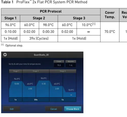
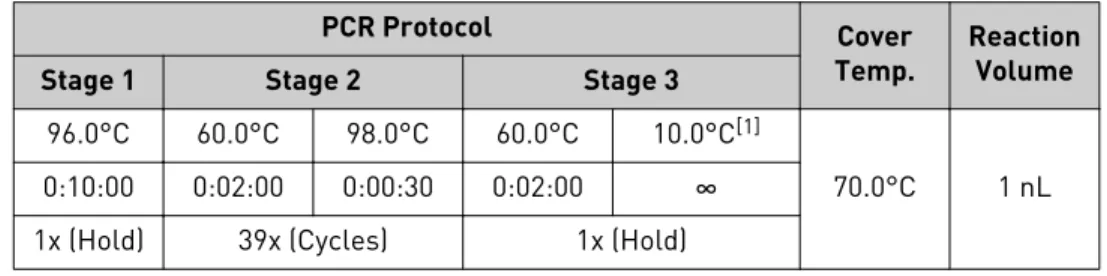
11. For optimal results, create a new method from the existing 3D template supplied with the ProFlex™ System and verify the pre-defined method for thermal cycling
the QuantStudio® 3D Digital PCR 20K Chips:
Table 1 ProFlex™ 2x Flat PCR System PCR Method
PCR Protocol Cover
Temp. ReactionVolume Stage 1 Stage 2 Stage 3
96.0°C 60.0°C 98.0°C 60.0°C 10.0°C[1]
70.0°C 1 nL 0:10:00 0:02:00 0:00:30 0:02:00 ∞
1x (Hold) 39x (Cycles) 1x (Hold)
[1] Optional step.
Note: For information on opening templates and programming the thermal cycler, see the ProFlex™ PCR System User Guide (Pub. no. MAN0007697). If you
cannot locate the 3D template on your ProFlex™ System, you may need to
upgrade the firmware (see “Prepare the thermal cycler“ on page 59).
The installation of the ProFlex™ System is complete and the thermal cycler is ready for
use.
Install the GeneAmp® PCR System 9700
Note: This section includes the essential procedures required to prepare the GeneAmp® PCR System 9700 for use. For complete instructions, see the GeneAmp®
PCR System 9700 Base Module User Manual (Pub. no. 4303481) or the GeneAmp® PCR
System 9700 Dual Flat Block User Manual (Pub. no. 4307808).
1. Unpack and place the GeneAmp® PCR System 9700 Base Module:
a. Open the package containing the GeneAmp® PCR System 9700 Base
Module.
b. Remove the packing crate from the GeneAmp® PCR System 9700 Package,
and verify that it contains all of the parts listed on the shipping manifest. If you have not received one or more of the parts, contact customer support for replacement (see “Customer and technical support“ on page 121).
Chapter 1 Getting Started
c. Remove the GeneAmp® PCR System 9700 Base Module from the package
and set it on a clean level surface, then remove the protective cover.
5 cm (2 in) 20 cm (8 in) 2 1 15.2 cm (6 in)
F1 F2 F3 F4
1 2 3 4 5 6 7 8 9 ENTER STOP
0 CE
F5
GeneAmp®
PCR System 9700
POWER
F1 F2 F3 F4
1 2 3 4 5 6 7 8 9 ENTER STOP
0 CE F5
GeneAmp®
PCR System 9700
POWER
1 QuantStudio® 3D Instrument
2 GeneAmp® PCR System 9700
IMPORTANT! The GeneAmp® PCR System 9700 must be installed on a level
surface.
Note: If not located next to the GeneAmp® PCR System 9700, the
QuantStudio® 3D Instrument requires only 15.2 cm (6 in) of clearance on
either side of the instrument.
d. Inspect the GeneAmp® PCR System 9700 Base Module for damage caused
during transportation.
If the instrument is damaged, note the location and appearance of the damage, then contact customer support for assistance.
2. Unpack and install the Dual Flat Block Module:
a. Open the package containing the Dual Flat Block Module.
b. Pull the lever out from the GeneAmp® PCR System 9700 Base Module.
F1 F2 F3 F4
1 2 3 4 5 6 7 8 9 ENTER STOP
0 CE
F5
GeneAmp®
PCR System 9700
POWER
Lever
c. Remove the Dual Flat Block Module from the package, remove the protective cover, place it onto the GeneAmp® PCR System 9700 Base
Module, then push the Dual Flat Block Module back to seat the electrical connections.
d. Push the lever into the GeneAmp® PCR System 9700 Base Module to secure
the Dual Flat Block Module.
Prepare the QuantStudio® 3D Digital PCR System for use
e. Inspect the Dual Flat Block Module for damage caused during transportation.
If the instrument is damaged, note the location and appearance of the damage, then contact customer support for assistance.
3. Set up the GeneAmp® PCR System 9700:
a. Open the package containing the QuantStudio® 3D Tilt Base for Dual Flat
Block GeneAmp® PCR System 9700 and install it beneath the thermal cycler.
11°
GeneAmp ® PCR System 9700
POWER F1 F2 F3 F4 F5 STOP 1 2 3 4 5 6 7 8 9 ENTER 0 CE
b. Open the packages containing the QuantStudio® 3D Digital PCR Chip
Adapter for Dual Flat Block GeneAmp® PCR System 9700 and install them.
Note: Each Chip Adapter includes a set of four alignment pegs that fit into the holes of a flat sample block. The Chip Adapter can fit onto either side of the sample block (right or left).
c. Connect the GeneAmp® PCR System 9700 power cord, power on the
thermal cycler, then wait for it to start (about 30 seconds).
The cooling fan powers up and the start-up screens appear. The GeneAmp®
PCR System 9700 is ready to use when the Main Menu displays.
08:00 AM 4/25/13 25.0°C
GeneAmp® PCR System 9700
F1 F2 F3 F4 F5
Run Create Edit Util User
Name:tc001 User:<<pe>> Version: 3.12
IMPORTANT! If the GeneAmp® PCR System 9700 does not start, check the
position of the Dual Flat Block Module. The instrument cannot be powered on if the module is seated incorrectly. If the GeneAmp® PCR System 9700
does not start, even after adjusting the Dual Flat Block Module, or if the screen contains any permanent patterns of lines or bars, contact technical support for assistance.
Chapter 1 Getting Started
d. When the GeneAmp® PCR System 9700 displays the main menu, confirm
that the version number displayed on the screen is 3.12 or greater. If the version number is less than 3.12, contact technical support to upgrade the instrument firmware before continuing.
IMPORTANT! The GeneAmp® PCR System 9700 must be running firmware
version 3.12 or greater to thermal cycle Digital PCR 20K Chips.
08:00 AM 4/25/13 25.0°C
GeneAmp® PCR System 9700 Name:tc001 User:<<pe>>
F1 F2 F3 F4 F5
Run Create Edit Util User
Version: 3.12 3.12 or
greater
4. From the Main menu, press Util (F4).
08:00 AM 4/25/13 25.0°C
GeneAmp® PCR System 9700
F1 F2 F3 F4 F5
Run Create Edit Util User
Name:tc001 User:<<pe>> Version: 3.12
5. From the Utilities screen, press Config (F3).
Utilities
Diag - Instrument diagnostics TmCalc - Calculates melting temp Config - Instrument configuration
F1 F2 F3 F4 F5
Diag TmCalc Config More Exit
6. From the Instrument Configuration screen, set the instrument time:
a. Use the Circular Key Pad to select the Time field.
b. Press the 24 Hr (F2) or PM (AM) (F3) soft keys until the format you want for the current time displays in the Time field.
c. Use the numeric keys to type in the hours followed by minutes.
d. Press Accept (F1) when your entries are complete.
F1 F2 F3 F4 F5
Accept 24Hr PM More Cancel
Instrument Configuration Time: 11:30 AM Date: 01/25/00 M/D/Y Run Time Printer: Off
Run Time Beep: Off
Note: CE clears an entry.
7. From the Configuration screen, set the instrument date:
a. Use the circular key to select the Date field.
Prepare the QuantStudio® 3D Digital PCR System for use
b. Press the D/M/Y or Y/M/D soft keys until the format you want for the current date displays in the Date field.
c. Use the numeric keys to enter the values into the Day, Month, and Year fields.
8. From the Main menu, create a user:
a. From the Main menu, press User (F5).
The Select User Name screen displays a list of names of all users who have been added to the instrument displays in a 4 x 5 matrix.
08:00 AM 4/25/13 25.0°C
GeneAmp® PCR System 9700
F1 F2 F3 F4 F5
Run Create Edit Util User
Name:tc001 User:<<pe>> Version: 3.12
b. Press New (F2) to add a new name to the list.
Select User Name
F1 F2 F3 F4 F5
Accept New Edit Delete Cancel
<<pe>> adrian doug peter
c. In the User Name field, enter an alphanumeric name up to six characters in length, then press Accept (F1) to accept a name.
Use ENTER key to select a character. User Name
F1 F2 F3 F4 F5
Accept Backsp Cancel
abcdefghi jklmnopqrj stuvwxyz .,-+/():=
The name you add or the name you select from a list of existing user names becomes the current user name. All new methods that you create are stored by default under the current user name.
d. Configure the Security Code screen according to your needs.
User Name: hank
Press PIN # to create a #. Then you set protection to Locked to prevent methods from being overwritten or deleted.
PIN number: None Protection: Unlocked
F1 F2 F3 F4 F5
Accept Name PIN# Cancel
Chapter 1 Getting Started
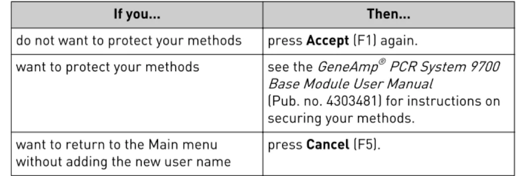
If you... Then...
do not want to protect your methods press Accept (F1) again.
want to protect your methods see the GeneAmp® PCR System 9700
Base Module User Manual
(Pub. no. 4303481) for instructions on securing your methods.
want to return to the Main menu
without adding the new user name press Cancel (F5).
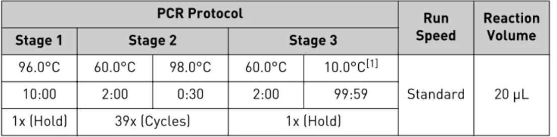
9. Program the GeneAmp® PCR System 9700 with the method for thermal cycling
QuantStudio® 3D Digital PCR 20K Chips:
Table 2 GeneAmp® PCR System 9700 PCR Method
PCR Protocol Run
Speed ReactionVolume Stage 1 Stage 2 Stage 3
96.0°C 60.0°C 98.0°C 60.0°C 10.0°C[1]
Standard 20 μL 10:00 2:00 0:30 2:00 99:59
1x (Hold) 39x (Cycles) 1x (Hold)
[1] Optional step.
2 Holds 2 Tmp 39 Cycles
1 Hold 96.0 10:00 60.0 2:00 60.0 2:00 98.0 0:30 10.0
Start Method: exp 001 Return
F1 F2 F3 F4 F5
Note: For information on programming the GeneAmp® PCR System 9700, see
the GeneAmp® PCR System 9700 Base Module User Manual (Pub. no. 4303481).
The installation of the GeneAmp® PCR System 9700 is complete and the components
are ready for use.
Connect the QuantStudio
®3D Instrument to a network
If you choose not to connect the QuantStudio® 3D Instrument using the setup wizard
during installation, you can connect it to a network at any time afterwards to streamline data transfer to the QuantStudio® 3D AnalysisSuite™ Software. If you
choose to connect your QuantStudio® 3D Instrument, see Appendix B, “Networking“
for the complete installation procedure, including guidelines for integrating the instrument into your laboratory network.
IMPORTANT! This document does not provide adequate detail to integrate the QuantStudio® 3D Instrument into all possible network architectures. Because your
laboratory network can contain advanced features (such as firewalls), we recommend that you consult a network administrator before connecting your instrument.
Connect the QuantStudio® 3D Instrument to a network
Connect the QuantStudio
®3D AnalysisSuite
™Software
You can connect to the QuantStudio® 3D AnalysisSuite™ Software before or after you
install the QuantStudio® 3D Digital PCR Instrument. The software supports two
methods of deployment (cloud and server), so the method that you follow will depend upon the deployment you purchased. Regardless of the deployment, you can use the AnalysisSuite™ Software web application to analyze data generated by your
QuantStudio® 3D Instrument. For more information, see the user documentation for
the QuantStudio® 3D AnalysisSuite™ Software.
Chapter 1 Getting Started
Prepare Samples and Load
Reactions
■
Prepare the DNA samples . . . 36■
Prepare the digital PCR reactions . . . 38■
Load the Digital PCR 20K Chips . . . 40■
Load the chips using the Chip Loader . . . 42■
Load chips manually . . . 50Prepare the DNA samples
We recommend the following best practices for the preparation of DNA template, genomic DNA (gDNA) or complementary DNA (cDNA), for use in digital PCR (dPCR) experiments. Because dPCR experiment strategy and methodology can vary significantly, sample preparation and template quality must be assessed on an individual basis.
To ensure high quality data, we recommend that the gDNA or cDNA template you use for dPCR experiments:
• Is extracted from the raw material that you are testing with an optimized protocol; salting-out procedures and crude lysates are not recommended • Does not contain PCR inhibitors
• Has an A260/230 and A260/280 ratio between 1.7 and 1.9
Note: The ratio of absorbance at 260 nm and 280 nm is used to assess the purity of DNA and RNA. A ratio of ~1.8 is generally accepted as “pure” for DNA; a ratio of ~2.0 is generally accepted as “pure” for RNA. If the ratio is appreciably lower in either case, it may indicate the presence of protein, phenol, or other
contaminants that absorb strongly at or near 280 nm.
The ratio of absorbance at 260 nm and 230 nm is used as a secondary measure of nucleic acid purity. The 260/230 values for “pure” nucleic acid are often higher than the respective 260/280 values. Expected 260/230 values are commonly in the range of 2.0-2.2. If the ratio is appreciably lower than expected, it may indicate the presence of contaminants that absorb at 230 nm.
The quantity of DNA template added to a dPCR reaction depends on the: • Concentration of gDNA or cDNA present in each sample
• Expected number of copies of the target sequence present in the genome or cDNA of your samples
2
Quality of DNA
Quantitation methods
Before performing digital PCR experiments, consider quantifying the amount of gDNA or cDNA in each sample.
We recommend the following methods of quantitation:
• Quant-iT™ assay nucleic acid quantitation using the Qubit® Quantitation Platform
or
• Use spectrophotometer to determine nucleic acid concentration
Should a target be present at a sufficiently high concentration in the sample of interest, it is possible that all reaction replicates will be positive, thus preventing the determination of the target concentration. In this case, the sample must first be diluted prior to running the digital PCR experiment.
In a digital PCR experiment performed on a QuantStudio® 3D Digital PCR System,
gDNA samples are diluted down to a limiting quantity, such that most individual PCR reactions contain either zero or one target molecule. The procedure for determining the optimal dilution for a sample differs depending on whether or not the target copy number per genome is known.
If the target copy number per genome of your samples is known, dilute the samples so that, when loaded on a QuantStudio® 3D Digital PCR 20K Chip, each through-hole
reaction will contain approximately 0.6 to 1.6 copies of the target sequence. For example, assuming 3.3 pg/copy of a given gene are present per human genome and a 865-pL reaction well volume, the stock gDNA in a given sample would be diluted down to 600 copies/μL or 1.98 ng/μL in the final reaction to give 0.6 copies per reaction well.
How to determine the target copy number per genome
To help determine copy number per genome, collect the following information:
1. If the source or species of the gDNA is known but the genome size of the organism of interest is unknown, refer to http://www.cbs.dtu.dk/databases/
DOGS/index.html to determine the size of the genome in question.
2. Once the size of the genome is known, determine the mass of the genome using the following formula:
m = ( n ) ( 1.096 × 10⁻²¹ g/bp )
where m is the genome mass in grams, and n is the genome size in base pairs. The following example calculates the mass of the human genome using the Celera Genomics estimate of 3.0 × 10⁹ bp (haploid):
m = (3.0 × 10⁹ bp) (1.096 × 10⁻²¹ g/bp) m = 3.3 × 10⁻¹² g or 3.3 pg
The example is relevant to any gene that is present at the “normal” rate of two copies per diploid genome, such as RNase P, and provides a basis to perform a digital screening experiment to determine the optimal digital range.
Sample dilution
Determine the
optimal dilution
when the target is
known
Chapter 2 Prepare Samples and Load Reactions
If the target copy number per genome is unknown, say for a locus of unknown copies per genome or RNA of unknown expression level, we recommend that you determine the optimal dilution by loading and imaging a dilution series of each sample at the expected digital range. By assaying three to four data points above and below the expected digital range, you ensure that one of the data points is within the optimal digital range. Should real-time data be available for the assay and sample being used, this can guide the starting and end point of the dilution series.
Prepare the digital PCR reactions
The following materials are required to prepare digital PCR reactions for use on the QuantStudio® 3D Digital PCR System.
• Genomic or complementary DNA sample(s)
• Fluorescent-labeled quantitative PCR reagents (TaqMan® Assays or SYBR® Green
primers) for your experiment
• QuantStudio® 3D Digital PCR Master Mix
• Gloves, powder-free, nitrile
• Cleanroom-grade, low-lint polyester wipes • Microcentrifuge
• Permanent marker or pen
• Calibrated pipettes and barrier tips, P10 to P1000
• Reaction tubes, DNase/RNase-free, non-stick or low-binding, 0.5-mL or 1.5-mL • TE Buffer, 1X Molecular Biology Grade
• Vortexer
• Water, DNase-free, sterile-filtered
When preparing samples for PCR amplification:
• Use a positive-displacement pipette or aerosol-resistant pipette tips. • Follow proper pipette-dispensing techniques to prevent aerosols.
• Wear clean gloves and a clean lab coat (not previously worn while handling amplified PCR products or used during sample preparation).
• Change gloves whenever you suspect that they are contaminated. • Maintain separate areas and dedicated equipment and supplies for:
– Sample preparation – PCR setup
– PCR amplification – Analysis of PCR products
• Never bring amplified PCR products into the PCR setup area.
• Open and close all sample tubes carefully. Centrifuge tubes before opening. Try not to splash or spray PCR samples.
• Keep reactions and components capped as much as possible.
• Clean lab benches and equipment periodically with 10% bleach solution. Use DNAZap™ Solution (PN AM9890).
Determine the
optimal dilution
when the target is
unknown
Required
materials
Guidelines for
PCR sample
preparation
Prepare the digital PCR reactions
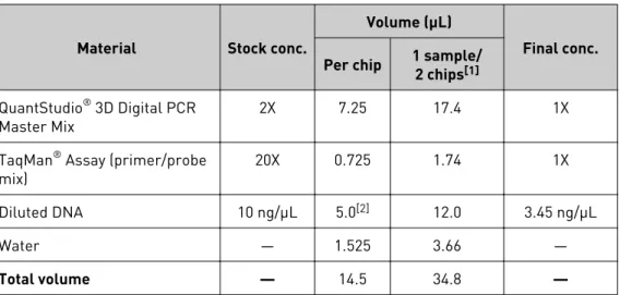
In this procedure, you will prepare the PCR reactions for the samples that you intend to load to QuantStudio® 3D Digital PCR 20K Chip. The volumes of the example
protocol have been adjusted so that two chips are run for each sample.
Table 3 PCR Reaction Mix
Material Stock conc.
Volume (μL)
Final conc. Per chip 1 sample/2 chips[1]
QuantStudio® 3D Digital PCR
Master Mix 2X 7.25 17.4 1X
TaqMan® Assay (primer/probe
mix) 20X 0.725 1.74 1X
Diluted DNA 10 ng/μL 5.0[2] 12.0 3.45 ng/μL
Water — 1.525 3.66 —
Total volume — 14.5 34.8 —
[1] Volumes include 20% excess to compensate for volume loss from pipetting.
[2] The recommended DNA volume is based upon a human gDNA sample at 10 ng/µL concentration with the target sequence present at two copies per diploid genome. This recommended volume will vary depending upon species, sample type, and sample concentration. For best results, we recommend adding sufficient DNA such that the concentration of target sequence in the final reaction is between 200 and 2,000 copies/µL.
1. Remove the following from storage and allow them to warm at room temperature:
• QuantStudio® 3D Digital PCR Master Mix
• TaqMan® Assay(s)
2. Review the concentration of your DNA samples, and prepare dilutions if necessary.
3. Gently invert the tube of Digital PCR Master Mix 10 times (or gently vortex on low-medium speed).
Prepare the
reaction mix and
samples
Chapter 2 Prepare Samples and Load Reactions
4. In a 0.5- or 1.5-mL low-binding reaction tube, prepare sufficient PCR reaction mix for your samples. Prepare the reaction mix at room temperature and scale the component amounts appropriately, depending on the number of samples that you are running.
Note: The following example assumes that you will load each sample to two Digital PCR 20K Chips.
Material
Volume (μL) 1 sample/
2 chips [1] 10 samples/20 chips[1]
QuantStudio® 3D Digital PCR Master Mix, 2X 17.4 174.0
TaqMan® Assay(s), 20X (primer/probe mix) 1.74 17.4
Water 3.66 36.6
Total volume 22.8 228.0
[1] Volumes include 20% excess to compensate for volume loss from pipetting.
5. Using a permanent marker, label a 0.5- or 1.5-mL reaction tube for each sample that you intend to run.
6. Vortex, then briefly centrifuge the DNA samples.
7. Transfer 22.8 μL of PCR reaction mix to each labeled reaction tube.
8. Transfer 12 μL of each sample, diluted to the appropriate concentration, to the corresponding low-binding reaction tube. Mix well by gently pipetting up and down after each transfer (or gently vortex on low-medium speed).
9. Cap the reaction tubes, then briefly centrifuge them and immediately proceed to load the Digital PCR 20K Chips.
IMPORTANT! For optimal results, load the Digital PCR 20K Chips as soon as possible after setting up the reactions. If you placed the reactions on ice, warm them to room temperature prior to loading.
Load the Digital PCR 20K Chips
After preparing your PCR reactions, you can load them into QuantStudio® 3D Digital
PCR 20K Chips manually or automatically using a QuantStudio® 3D Digital PCR Chip
Loader.
To load and seal Digital PCR 20K Chips:
• Automatically — See “Load the chips using the Chip Loader “ on page 42. • Manually — See “Load chips manually“ on page 50.
Load the Digital PCR 20K Chips
To ensure the proper processing and analysis of your loaded Digital PCR 20K Chip, handle them according to the following guidelines:
• Always wear powder-free gloves when loading and sealing Digital PCR 20K Chips.
IMPORTANT! Never handle Digital PCR 20K Chips or Chip Case Lids without gloves. Oils from your hands can contaminate the components and interfere with thermal cycling and imaging.
• Handle the Digital PCR 20K Chips and Chip Case Lids as follows:
– Hold the Digital PCR 20K Chips and Chip Case Lids by gently gripping them by their sides.
– Do not touch the surface of the Digital PCR 20K Chips. If you accidentally touch the surface of a chip, discard it.
Note: Debris or excess sample on the Chip Case Lid can fluoresce and interfere with thermal uniformity.
X0300036
• If necessary, use a permanent pen or marker to label the back of each loaded Chip Case to aid in sample tracking.
• Load each Digital PCR 20K Chip within 2 hours after opening it.
• Load Digital PCR 20K Chips in alphanumeric order (according to Digital PCR 20K Chip serial number) to avoid data-entry errors.
• Apply a Chip Case Lid and add Immersion Fluid to each Digital PCR 20K Chip immediately after loading it to avoid evaporation.
• Load and seal Digital PCR 20K Chips in batches of up to 24 chips (the maximum number that can be loaded onto one thermal cycler).
• If you do not intend to load an opened Digital PCR 20K Chip immediately, cover the chip using the aluminum plate found within the packaging to prevent contamination.
• When not in use, store the Chip Sealant within its original protective package to prevent the sealant in the syringe tip from curing. The Chip Sealant can be stored with the syringe tip attached.
• Use all of the Immersion Fluid within 60 minutes of uncapping the syringe. Once a syringe is opened, you cannot reattach the cap for later use.
• Thermal cycle Digital PCR 20K Chips within 2 hours after loading them.
Guidelines for
loading and
sealing Digital
PCR 20K Chips
Chapter 2 Prepare Samples and Load Reactions
Load the chips using the Chip Loader
The following procedure explains how to load QuantStudio® 3D Digital PCR 20K
Chips automatically using a QuantStudio® 3D Digital PCR Chip Loader. This
procedure assumes that you have prepared your PCR reactions as explained in “Prepare the reaction mix and samples“ on page 39 and are ready to load them onto Digital PCR 20K Chips.
The following materials are required to load and seal QuantStudio® 3D Digital PCR
20K Chips for use on the QuantStudio® 3D Digital PCR System.
• Prepared digital PCR reactions (from the previous section) • QuantStudio® 3D Digital PCR 20K Chips
• QuantStudio® 3D Digital PCR Chip Case Lids
• QuantStudio® 3D Digital PCR Sample Loading Blades
• Immersion Fluid • Immersion Fluid Tip
• QuantStudio® 3D Digital PCR Chip Loader
• UV-Activated Chip Sealant Syringe • Isopropanol
• Gloves, powder-free, nitrile • Scissors
• Cleanroom-grade, low-lint polyester wipes • Microcentrifuge
• Pipettes and tips, P10 to P1000 • Vortexer
The LED on top of the QuantStudio® 3D Digital PCR Chip Loader indicates the
instrument status. The light is illuminated at all times when the Chip Loader is powered on and changes color according to instrument readiness.
Color State Status
Blue Solid The Chip Loader is booting.
Flashing The chip nest is not at temperature or the lever arm is not fully open.
Green Solid The Chip Loader is at the correct temperature and ready to load a chip.
Flashing The Chip Loader is loading a Digital PCR 20K Chip. Red Flashing The Chip Loader has encountered an error.
Materials
required
QuantStudio
®3D
Digital PCR Chip
Loader status
light
Load the chips using the Chip Loader