REDIRECTED FREE EXPLORATION WITH DISTRACTORS: A LARGE-SCALE, REAL-WALKING LOCOMOTION INTERFACE
Tabitha C. Peck
A dissertation submitted to the faculty of the University of North Carolina at Chapel Hill in partial fulfillment of the requirements for the degree of Doctor of Philosophy in the Department of Computer Science.
Chapel Hill 2010
Approved by:
Henry Fuchs
Mary C. Whitton
Frederick P. Brooks, Jr.
Victoria Interrante
Dennis R. Proffitt
c
2010
ABSTRACT
TABITHA C. PECK: Redirected Free Exploration with Distractors: A Large-Scale, Real-Walking Locomotion Interface
(Under the direction of Henry Fuchs and Mary C. Whitton)
Immersive Virtual Environments (VEs) enable user controlled interactions within the environment such as head-controlled point-of-view and user-controlled locomotion. In the real world people usually locomote by walking; walking is simple and natural, and enables people not only to move between locations, but also to develop cognitive maps, or mental representations, of environments. People navigate every day in the real world without problem, however users navigating VEs often become disoriented and frustrated, and find it challenging to transfer spatial knowledge acquired in the VE to the real world.
PREFACE
ACKNOWLEDGMENTS
I would like to thank my advisors, Henry Fuchs and Mary Whitton. I thank Mary for all of the time she spent helping me develop RFED and design user studies, for encouraging me to learn statistics, and for her countless hours editing papers and teaching me how to write. I thank Henry for his continuous enthusiasm, inspiring ideas, and help in finding a dissertation topic that I really interested me. This dissertation would not exist without all of Mary and Henry’s patience and hard work. I would also like to thank the rest of my committee, Frederick Brooks, Victoria Interrante, Dennis Proffitt, and Anthony Steed for all of their helpful advice and feedback.
I would like to thank Sharif Razzaque for encouraging me to continue his work on Redirected Walking and taking time out of his busy schedule to answer any questions I had about Redirected Walking.
I wish to thank the EVE research group for all of their feedback on presentations, advice on study designs, and time fixing EVEIL bugs. I especially would like to thank:
• Eric Burns for encouraging me to come to my first EVE meeting
• Luv Kohli and Chris VanderKnyff for the help with EVEIL
• Chris Oates for recording audio and helping with models
• Jeremy Wendt for letting my use his GUD-WIP interface
I would like to thank Eric Knisley for modeling the distractor hummingbird.
I would like to thank The Link Foundation and The Anita Borg Institute for funding parts of this work.
time here. I would like to personally thank Courtney Ferriter, Kelli Gaskill, Missy Wood, Janet Jones, David Harrison, John Thomas, Bil Hays, David Marshburn, Andrei State, Russ Taylor, and Gary Bishop.
I would also like to thank my many friends and classmates especially Anish Chandak, Brian Clipp, Cory Quammen, Dave Millman, David Feng, Ilknur Kaynar Kabul, Kirsten Morrison, Keith Lee, Srinivas Krishnan, Stephen Olivier, Chad Spensky, Russ Gayle, Jason Sewall, Sarah Kennedy, Xiaoxiao Liu, and Zhimin Ren.
I would like to The Trio, Brad Moore, Tim Thirion, and Rick Skarbez for getting my through my first year. Especially Brad Moore for being an amazing friend.
I would like to that Catie Welsh, Laura Kassler, Caroline Green, and Jeanette Olli for the many much needed girls nights.
I thank my parents, Martha and Earl Peck for always encouraging and supporting me to excel throughout my life. This dissertation would not exist without you and for that reason I have dedicated this dissertation to you.
TABLE OF CONTENTS
LIST OF ABBREVIATIONS 1
1 Overview 1
1.1 Theory Behind RFED Development . . . 2
1.2 Thesis Statement . . . 4
1.3 Overview of Dissertation . . . 4
1.4 Overview of User Studies and Results . . . 5
1.4.1 Distractors: Chapter 5 . . . 5
1.4.2 Redirected Free Exploration with Distractors versus Real Walking: Chapter 6 . . . 5
1.4.3 Redirected Free Exploration with Distractors>Walking-In-Place and Joystick: Chapter 7 . . . 6
2 Perception 7 2.1 Sensory Systems . . . 7
2.1.1 The Visual System . . . 7
2.1.2 Depth Cues . . . 8
2.1.3 The Vestibular System . . . 10
2.1.4 The Interaction of the Visual and Vestibular Systems . . . 12
2.1.5 Other Sensory Systems . . . 13
2.2 Visual Perception . . . 14
2.2.1 Gibson’s Theory of Perception . . . 15
2.2.3 Perception and VEs: Studies that Guide Large-Scale Real-Walking
Interface Design . . . 19
2.2.4 The Dorsal and Ventral Streams: Vision for Action and Vision for Perception . . . 26
3 Virtual Locomotion 28 3.1 Locomotion Interfaces . . . 28
3.1.1 Introduction . . . 28
3.1.2 Joystick . . . 29
3.1.3 Walking-in-Place . . . 30
3.1.4 Treadmills . . . 31
3.1.5 Real-Walking Interfaces . . . 32
3.1.5.1 Scaled-Translational Gain . . . 32
3.1.5.2 Seven League Boots . . . 33
3.1.5.3 Motion Compression . . . 33
3.1.5.4 Redirected Walking . . . 33
3.1.6 Reorientation Techniques . . . 34
3.2 Simulator Sickness . . . 35
3.3 Navigation . . . 37
4 Redirected Free Exploration with Distractors 39 4.1 Introduction . . . 39
4.2 Efficient Redirection . . . 41
4.2.1 Direction Prediction . . . 45
4.2.2 Steering . . . 49
4.3 Distractors . . . 50
4.4 Deterrents . . . 53
5 Distractors 55 5.1 Introduction . . . 55
5.2.1 Equipment . . . 58
5.2.2 Experiment 1 . . . 58
5.2.2.1 Participants . . . 58
5.2.2.2 Experimental Design . . . 58
5.2.2.3 Results . . . 62
5.2.2.4 Discussion . . . 64
5.2.3 Experiment 2 . . . 66
5.2.3.1 Participants . . . 66
5.2.3.2 Experimental Design . . . 67
5.2.3.3 Results . . . 69
5.2.3.4 Discussion . . . 71
5.2.4 Experiment 3 . . . 73
5.2.4.1 Participants . . . 73
5.2.4.2 Experimental Design . . . 74
5.2.4.3 Results . . . 77
5.2.4.4 Discussion . . . 79
5.3 Conclusion . . . 81
6 An Evaluation of Navigational Ability Comparing Redirected Free Ex-ploration with Distractors to Real Walking 84 6.1 Experiment . . . 84
6.1.1 Hypotheses and Measures . . . 86
6.1.2 Participants . . . 87
6.1.3 Equipment . . . 87
6.1.4 Experimental Design . . . 88
6.1.4.1 Training . . . 88
6.1.4.2 Part 1: Na¨ıve Search . . . 90
6.1.4.3 Part 2: Primed Search . . . 90
6.2 Results and Discussion . . . 91
6.2.2 Part 2: Primed Search . . . 96
6.2.3 Post Tests . . . 100
6.3 Conclusion . . . 102
7 An Evaluation of Navigational Ability Comparing Redirected Free Ex-ploration with Distractors to Walking-in-Place and Joystick 104 7.1 Conditions . . . 105
7.1.1 Redirected Free Exploration with Distractors (RFED) . . . 105
7.1.2 Walking-In-Place (WIP) . . . 105
7.1.3 Joystick (JS) . . . 105
7.2 Hypotheses and Measures . . . 106
7.3 Participants . . . 106
7.4 Equipment . . . 106
7.5 Experimental Design . . . 107
7.5.1 Training . . . 107
7.5.2 Part 1: Na¨ıve Search . . . 108
7.5.3 Part 2: Primed Search . . . 108
7.6 Results and Discussion . . . 109
7.6.1 Part 1: Na¨ıve Search . . . 109
7.6.2 Part 2: Primed Search . . . 112
7.6.3 Post Tests . . . 117
8 Conclusion and Future Work 119 8.1 Discussion of Results . . . 119
8.2 Future Work . . . 121
8.2.1 RFED Algorithm . . . 122
8.2.1.1 Redirection . . . 122
8.2.1.2 Distractors . . . 123
8.2.1.3 Deterrents . . . 124
8.2.2.1 Wide Field-Of-View Head-Mounted-Displays . . . 125
8.2.2.2 Training . . . 125
8.2.3 Projector systems . . . 125
8.2.3.1 Multiuser interfaces . . . 126
8.2.3.2 Size of the tracked space . . . 126
A Questionnaires 127 A.1 Modified Slater-Usoh-Steed Presence Questionnaire . . . 127
A.2 Embedded Questions . . . 128
A.3 Simulator Sickness Questionnaire . . . 129
A.4 Embedded Questions . . . 130
LIST OF TABLES
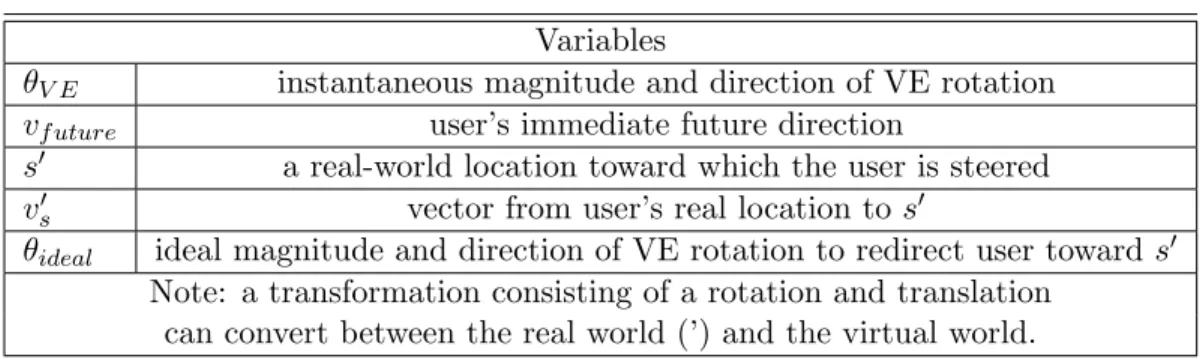
4.1 Efficient Redirection Variables . . . 41 4.2 Turn distractor on values for distance and time . . . 52 5.1 Experiment 1 - Mean HIGH scores on SUS Presence Questionnaire . . . 61 5.2 Experiment 1 - Results of Logistic Regression of SUS Presence Questionnaire.
Statistically significant results are marked with a box. . . 62 5.3 Experiment 2 - Mean percentage of HIGH scores on SUS Presence
Question-naire . . . 69 5.4 Experiment 2 - Results of Logistic Regression of SUS Presence Questionnaire 69 5.5 Experiment 3 - Mean percentage of HIGH scores on SUS Presence
Question-naire . . . 76 5.6 Experiment 3 - Results of Logistic Regression of SUS Presence Questionnaire.
Statistically significant results are marked with a box. . . 77 5.7 Experiments 2 and 3 - Results of Logistic Regression of SUS Presence
LIST OF FIGURES
2.1 The anatomy of the human eye (Connect, 2010). . . 8 2.2 A cross-eye stereo photo pair of a kasuga lantern on Wooded Island, Jackson
Park, Chicago, Illinois (Scarborough, 2007). . . 9 2.3 The School of Athens by Raphael (1483-1520). The superimposed lines are
perspective parallel lines meeting at “infinity” in the center of the painting (Raphael, 1520). . . 9 2.4 The ear (Northwestern, 2001a). . . 10 2.5 The semicircular canals and the utricle and saccule. Notice that three the
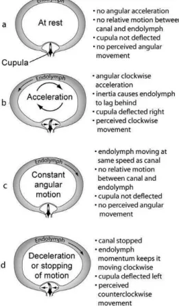
semicircular canals are orthogonal to each other (Northwestern, 2001b). . . 11 2.6 Acceleration in a semicircular canal (NASA, 2003). . . 12 2.7 The figure shows an otolith membrane with cilia and otoconia crystals. “Forces
acting on the head and the resulting displacement of the otolithic membrane of the utricular macula. For each of the positions and accelerations due to translational movements, some set of hair cells will be maximally excited, whereas another set will be maximally inhibited. Note that head tilts produce displacements similar to certain accelerations” (Sinauer Associates, 2001). 13 2.8 The contribution of the visual and vestibular (inertial) senses, in the time
domain, to the perception of a step in rotational velocity (about the yaw axis) (adapted from Borah et al., 1979). . . 14 2.9 The visual-vestibular crossover. This graph shows, in the frequency domain,
the relative contributions of visual and linear vestibular cues to postural stability (adapted from Duh et al., 2004) . . . 15 2.10 Applying different textures makes the surface appear to be vertical or sloping.
(Redding, 2000) . . . 16 2.11 The texture causes the image to appear to have a ripple shape (Wiersma,
2007). . . 17 2.12 The texture provides information about depth, size, and orientation of the
boxes (Schouten, 2003). . . 18 2.13 A. Outward radial optic flow. B. Lamellar, or horizontal optic flow. . . 19 2.14 Based on an image from (Bruce et al., 2003). A. The room swings toward the
2.15 Left. As the person looks directly along the heading vector, optic flow ra-diates outward from the center of vision. Right. A prism is placed in front of the eye which shifts the visual location of the goal and the location of the radial optic flow. The optic flow on the retina is the same pattern as on the
left but shifted due to the prism. Based on an image from (Rushton et al., 1998). . . 22 2.16 The four environments used in (Warren et al., 2001) with different amounts
of optic flow. A.a target line,B.a target line and textured ground plane,C.
a fully textured environment with a doorway,D.a fully textured environment with doorway and posts. Based on an image from (Warren et al., 2001). . 24 2.17 Heading error as a function of time and amount of optic flow. An image from
(Warren et al., 2001). . . 25 2.18 The ventral and dorsal streams. Based on an image from (Zuj et al., 2004). 27 3.1 A visual representation of motion interfaces for virtual environments. . . 28 3.2 An xBox 360 game controller. The arrows point to the two joysticks on the
controller. This joystick was used in the study described in Chapter 7. . . . 30 3.3 A soldier positioned on omni-directional treadmill, inside of CAVE
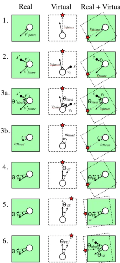
environ-ment. (ARL HRED, 2006) . . . 32 4.1 The six steps of efficient redirection. These steps are discussed in Section
4.2. The star is a virtual reference point. Notice that the star moves with the VE inStep 5. . . 43 4.2 Direction prediction is unstable when the user look direction, vlook is used
forvf uture. As a user turns her head back and forth, the look direction,vlook0
quickly changes to the right and left ofs0, changing the rotation direction of
θV E from positive and negative. . . 45
4.3 Step 1. Define a bidirected graph over the VE. Step 2. Identify the node closest to the user (p), and the nodes connected to p, (pa and pb). Step 3.
Define vectors va and vb from the user to connected nodes pa and pb. Step
4. Calculate and compare the angles α and β between the user direction vector, vuser (Equation 4.1) and vectors va and vb. Since α is smaller than
β, set va asvf uture. . . 48
4.4 Version 1. Turn distractor on: The user is stopped by a distractor when he crosses a boundary near the edge of the tracked space. Turn distractor off: When the VE has rotated by θ0ideal around the user. Version 2. Turn dis-tractor on: The disdis-tractor appears based on a function of the user’s distance to the center of the tracked space and the time since the previous distractor. Turn distractor off: When the VE has rotated a fraction of θideal based on
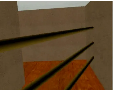
the distance of the user from the center of the tracked space. . . 51 4.5 A screen shot of the horizontal bars used as deterrents in the version 2
5.3 The path of all distractors is defined as an arc (dashed line) directly in front of the user. The distractor moves with sinusoidal displacement along the arc causing the participant to turn her head back and forth to keep the distractor in view. The distractor is displayed 1.75 meters away from the user, and the height of all distractors is approximately 1.5 meters. The same path trajectory is used for all distractors in each of the three experiments presented in this chapter. . . 60 5.4 Experiment 1–Legend . . . 60 5.5 Experiment 1–User rated preference scores from 1 (most preferred) to 4 (least
preferred). Standard box-and-whisker plots with the median in red. . . 62 5.6 Experiment 1–User rated naturalness scores from 1 (most natural) to 4 (least
natural). Standard box-and-whisker plots with the median in red. . . 63 5.7 Experiment 1–User forced-choice comparisons of preference across ROTs. . 64 5.8 Experiment 1–User forced-choice comparisons of naturalness across ROTs. . 64 5.9 Butterfly distractor used in Experiment 2. . . 66 5.10 Experiment 2–Legend . . . 69 5.11 Experiment 2–User rating - “I felt like I was turning around” with ± 1
standard deviation. . . 70 5.12 Experiment 2–User rating - “I saw the virtual world rotating” with ± 1
standard deviation. . . 71 5.13 Experiment 2–User rated preference scores from 1 (most preferred) to 3 (least
preferred). Standard box-and-whisker plots with the median in red. . . 72 5.14 Experiment 2–User rated naturalness scores from 1 (most natural) to 3 (least
natural). Standard box-and-whisker plots with the median in red. . . 73 5.15 Experiment 2–User forced-choice comparisons of preference and naturalness
across ROTs. . . 74 5.16 Hummingbird distractor used in Experiment 3. . . 75 5.17 Experiment 3–Legend . . . 76 5.18 Experiments 2 and 3–User rating - Mean percentage of HIGH scores on SUS
Presence Questionnaire. . . 78 5.19 Experiment 3–User rating - “I felt like I was turning around” with ± 1
standard deviation. . . 79 5.20 Experiment 3–User rating - “I saw the virtual world rotating” with ± 1
standard deviation. . . 80 5.21 Experiment 3–User rated preference scores from 1 (most preferred) to 3 (least
preferred). Standard box-and-whisker plots with the median in red. . . 81 5.22 Experiment 3–User rated naturalness scores from 1 (most natural) to 3 (least
5.23 Experiment 3–User forced-choice comparisons of preference and naturalness across ROTs. . . 83 6.1 An overhead view of the mazes and target locations used in the na¨ıve and
primed searches. Participants started each maze in the bottom left corner. 85 6.2 A participant walking through the maze in Part 1, a na¨ıve search. The blue
box is the boundary of the tracked space and the red box is the boundary of the VE. The left most image is the participant’s real path over time. The right most image is the participant’s virtual path over time. The start of the participant’s real and virtual paths are dark and the ends are light. The center image is the final composite of the left and right images with the final transformation applied to the VE and user’s virtual path. . . 85 6.3 A screen shot of the virtual avatar hand selecting Target 1, the red target. 88 6.4 An overhead view of the training maze. . . 89 6.5 A screen shot of the ghost distractor. . . 90 6.6 A summary of the predefined equivalence values and results from the
equiva-lence tests performed in this study. Bold faced 95% CI values were compared to the predefined equivalence values to evaluate RFED being “no worse” that RW. “No worse” than results are highlighted with dashed lines. . . 92 6.7 The virtual-space routes taken by the median performing participant from
each locomotion interface during the na¨ıve search. A: real walking (virtual space = real space);B:Redirected Free Exploration with Distractors. Notice the areas in B. where the participant continues walking in the same area. This is caused by distractor appearances. Participants started in the bottom left corner; path segment color follows the colors of the rainbow, ROYGBV, to mark the participant’s finding and selecting a new target. . . 92 6.8 The average total distance traveled, and the average number of revisited areas
between RW and RFED during Part 1, a na¨ıve search, with± one standard deviation error bars. . . 94 6.9 Map placing of targets for a na¨ıve search. The 95% CI of the difference of the
means of RFED and real walking is the horizontal bar and the “less accurate” zone is on the left. Since the 95% CI is greater than the “less accurate” zone, RFED is “no worse” than real walking. . . 95 6.10 The average percentage of correctly placed, and correctly placed-and-labeled
targets on maps for RW and RFED during Part 1, a na¨ıve search. With ±
one standard deviation error bars. . . 96 6.11 The virtual route of an RFED participant to each target during the primed
6.12 The average distance traveled between successive targets, and the average number of wrong turns to each target for RW and RFED during the primed search. . . 98 6.13 Pointing data from all participants, with RW and RFED as separate rows.
Each circle is the composite data of the differences in degrees between point-ing directly to a specific target (denoted as 12 o’clock) and where the partic-ipant actually pointed. Each circle contains all pointing data to the specific numbered and colored target, from all participants in the corresponding con-dition. The white angle lines provide a reference at ±30◦. . . 99 6.14 Total pointing time from all participants, for RW and RFED conditions.
Each column is the composite data, from all participants in RW and RFED, of the total time taken to point to the target of the specified color. . . 100 6.15 Map placing-and-labeling of targets for the primed search. The 95% CI of
the difference of the means of RFED and real walking is the horizontal bar and the “less accurate” zone is on the left. Since the 95% CI is greater than the “less accurate” zone, RFED is “no worse” than real walking. . . 101 6.16 The average number of “high” presence scores and the average simulator
sickness score for RFED and RW with ±one standard deviation error bars. 101 7.1 The 15.85m x 15.85m mazes used in this study. Left: the maze used during
the naive search with seven targets. Right: the maze used during the primed search with six targets. Participants started each maze in the bottom left corner. . . 105 7.2 The GUD WIP locomotion interface set-up. . . 106 7.3 The virtual routes of three participants, one using each of the three
locomo-tion interfaces, when performing the naive search. The routes of the median performing participants in each locomotion interface is displayed. A. The virtual route a participant took using RFED. Note the side-to-side head bob characteristic of real walking. B.The virtual route a participant took using WIP. C.The virtual route a participant took using JS. . . 110 7.4 The total average distance traveled and the average number of repeated
routes, by locomotion interface, when performing the naive search to find seven targets within the maze, with±1 standard deviation. . . 110 7.5 The average percentage of correctly placed and correctly labeled targets on
paper maps after completing the naive and primed searches. ±1 standard deviation. . . 112 7.6 The virtual paths with corresponding real path taken by a participant in the
7.7 The total average distance traveled and the average number of “wrong turns”, by locomotion interface when performing the primed search to each of the six targets within the maze. . . 114 7.8 The pointing data for all participants to each of the six targets(columns) by
LIST OF ABBREVIATIONS
3D Three-Dimensional FOE Field of Expansion FOR Field of Regard FOV Field of View
MC Motion Compression POV Point Of View RDW Redirected Walking
RFED Redirected Free Exploration with Distractors ROT Reorientation Technique
CHAPTER 1
Overview
Virtual environments (VEs) have been described as a window into a “mathematical won-derland” of computer generated worlds (Sutherland, 1965). VEs not only enable looking through a window, but walking through a door into a computer generated world. Immer-sive VEs enable user-controlled interactions within the environment such as head-controlled point-of-view and user-controlled locomotion. In the real world people usually locomote by walking; walking is simple and natural, and enables people not only to move between lo-cations, but also to develop cognitive maps, or mental representations, of environments. People navigate every day in the real world without problem, however users navigating VEs often become disoriented and frustrated, and find it challenging to transfer spatial knowl-edge acquired in the VE to the real world (Durlach and Mayor, 1995; Psotka, 1995; Darken and Sibert, 1996; Grant and Magee, 1998).
In this dissertation I develop and demonstrate the effectiveness of a new locomotion interface for head-mounted displays, Redirected Free Exploration with Distractors (RFED) that enables people to freely walk in large scale VEs1. RFED is the combination of distrac-tors—objects, sounds, or combinations of objects and sounds in the VE that encourage peo-ple to turn their heads, andredirection—making the user turn herself by interactively and imperceptibly rotating the virtual scene about her while she is turning her head (Razzaque, 2005). I demonstrate through user studies that compare RFED to a real-walking locomotion interface that RFED does not diminish user ability to navigate. I further demonstrate that users navigate better in RFED than with joystick and walking-in-place locomotion inter-faces. Additionally, RFED does not significantly increase simulator sickness when compared
1
to real walking, walking-in-place, and joystick interfaces.
1.1
Theory Behind RFED Development
Navigation is important for VE training applications where spatial understanding of the VE must transfer to the real world. Navigation is the combination of wayfinding and locomotion and as such is both cognitive and physical. Wayfinding is the cognitive aspect of navigation and does not involve movement. Wayfinding is the building and maintaining of a cognitive map, and is used to determine how to get from one location to another. Locomotion, the physical aspect of navigation, is defined as moving, physically or virtually, between two locations (Darken and Peterson, 2002). Specifically, navigation is essential for large VEs including exploring virtual cities, training ground troops, or visiting virtual models of houses.
Previous research suggests that users navigate best in VEs with real-walking locomo-tion interfaces (Ruddle and Lessels, 2009). Locomolocomo-tion interfaces that provide users with vestibular and proprioceptive feedback improve user navigation performance and are less likely to cause simulator sickness than locomotion interfaces that do not stimulate both the proprioceptive and vestibular systems (Chance et al., 1998; Ruddle and Lessels, 2009). For this reason, RFED is designed to enable users to really walk in the VE. This is in contract to other VE locomotion2 interfaces such as walking-in-place, omni-directional treadmills, or bicycles (Hollerbach, 2002; Darken et al., 1997) that require physical-input from the user, but do not stimulate both the proprioceptive and vestibular systems in the same way as really walking. RFED enables people to really walk, thus supporting user navigation by stimulating both the proprioceptive and vestibular systems.
Real-walking locomotion interfaces are believed to enable better user navigation, are more natural, and produce a higher sense of presence than other locomotion interfaces (Slater et al., 1995b; Usoh et al., 1999). However, because user motion must be tracked,
2
VEs using a real-walking locomotion interface have typically been restricted in size to the area of the tracked space. Current interfaces that enable real walking in larger-than-tracked-space VEs include redirected walking (RDW) (Razzaque et al., 2001; Razzaque et al., 2002; Razzaque, 2005), scaled-translational-gain (Robinett and Holloway, 1992; Williams et al., 2006a; Williams et al., 2007), seven-league boots (Interrante et al., 2007), and motion compression (MC) (Nitzsche et al., 2004; Su, 2007). Each of these interfaces transforms the VE or user motion by rotating the environment or scaling user motion. While these transformations enable large-scale real-walking in VEs, the effect of the transformations on navigational ability is unknown. I evaluate the effect of rotational transformations on navigational ability through two user studies presented in Chapters 6 and 7.
Additionally, when freely walking in the locomotion interfaces mentioned above, users may find themselves about to walk out of the tracked space, and possibly into a real wall. When a user nears the edge of the tracked space a reorientation technique (ROT) must be used to prevent the user from leaving the tracked space (Peck et al., 2009). ROTs must stop the user and rotate the VE around her current virtual location, returning the immediately predicted path into the tracked space. The user must also reorient herself by physically turning around in the real environment so she can follow her desired path in the newly-rotated VE. ROTs are required for real-walking interfaces enabling free exploration of large VEs and are not required for interfaces using devices that constrain user physical movement such as joysticks, walking-in-place interfaces, treadmills, or bicycles (Brooks, 1987; Chris-tensen et al., 2000; Darken et al., 1997; Iwata, 1999; Slater et al., 1995a). However, many current ROT implementations cause breaks in presence by using disembodied voices, or quickly spinning the VE around the user, which detract from the immersive VE experience. In this dissertation I develop and evaluate a new ROT, distractors, through three user studies (Chapter 5). Distractors are objects, sounds, or combinations of objects and sounds in the VE that encourage people to turn their heads. Redirection, is best accomplished while the head is turning, is “making the user turn herself by interactively and imperceptibly rotating the virtual scene about her,” (Razzaque, 2005) .
with Distractors (RFED) which enables real walking to stimulate the proprioceptive and vestibular systems to support user navigation. RFED enables large-scale real walking by combiningdistractorsandredirection (Chapter 4). I then evaluated user navigational ability and simulator sickness when using RFED compared to real-walking, walking-in-place, and joystick interfaces (Chapters 6 and 7).
1.2
Thesis Statement
A large-scale, real-walking locomotion interface using distractors and redirection enables people to freely locomote in larger-than-tracked-space virtual environments, navigating no worse than real-walking and better than joystick and walking-in-place interfaces.
To demonstrate the validity of my thesis statement, I
1. Develop a large-scale, real-walking locomotion interface using distractors and redirec-tion, Redirected Free Exploration with Distractors (RFED), that enables people to freely locomote larger-than-tracked-space virtual environments
• Develop and Evaluate Distractors through three user studies (Chapter 5)
• Develop and implement RFED (Chapter 4)
• Demonstrate that RFED users can freely locomote in larger-than-tracked-space VEs in two user studies (Chapters 6 and 7)
2. Compare navigational ability
• RFED users navigate no worse than users who really walk (Chapter 6)
• RFED users navigate better than users of walking-in-place and joystick interfaces (Chapter 7)
1.3
Overview of Dissertation
ROT, through three user studies. Chapter 4 discusses the design of RFED in detail and should be a reference for future RFED implementations. Chapters 6 and 7 present two user studies evaluating user navigational ability when using RFED by comparing it to real walking, walking-in-place, and joystick interfaces. Chapter 8 presents an overview of the final results and discusses future research areas that may improve RFED implementations. The questionnaires used in the user studies can be found in Appendix A. The rest of Chapter 1 presents an overview and results of the five user studies.
1.4
Overview of User Studies and Results
1.4.1 Distractors: Chapter 5
Virtual environments that use a real-walking locomotion interface have typically been re-stricted in size to the area of the tracked lab space. Techniques proposed to lift this size constraint, enabling real walking in VEs that are larger than the tracked lab space, all require reorientation techniques (ROTs) in the worst-case situation–when a user is close to walking out of the tracked space. I propose a new ROT using visual and audial distractors– objects in the VE that the user attends while the VE rotates–and compare my method to current ROTs through three user studies. ROTs using distractors were preferred and ranked more natural by users. Users were also less aware of the rotating VE when ROTs with dis-tractors were used. The findings also suggest that improving visual realism and adding sound to distractors increased a user’s feeling of presence. Much of the work reported in this chapter was published in (Peck et al., 2009).
1.4.2 Redirected Free Exploration with Distractors versus Real Walking:
Chapter 6
Redirected Free Exploration with Distractors (RFED) to support user navigation in large-scale VEs. The interface is discussed in Chapter 4.
I compared RFED to the current best interface, really-walking, by conducting a user study measuring navigational ability. The results show that RFED users can really-walk through VEs that are larger than the tracked space and can point to targets and complete maps of VEs no worse than when really walking (Peck et al., 2010).
1.4.3 Redirected Free Exploration with Distractors > Walking-In-Place
and Joystick: Chapter 7
CHAPTER 2
Perception
This chapter introduces the reader to the sensory systems that are stimulated by Redirected Free Exploration with Distractors. After defining the physical systems that are relevant for RFED, I discuss the psychology of visual perception and psychology studies that suggest directions for future development of RFED.
2.1
Sensory Systems
The human sensory systems are part of the nervous system and have sensory receptors that receive stimulation from internal and external sources. The stimuli pass information to the brain via neural pathways, and the brain then processes the information. RFED takes advantage of the human sensory systems by stimulating the senses with rendered images that do not match what should be seen based on the user’s physical actions. To understand why people do not “perceive” these inaccuracies and yet physically respond to changes in rendered images, e.g. rotating or scaling the VE, requires an understanding of visual perception and the human sensory systems. An understanding of human perceptual systems provides insight for future RFED developers and guides future RFED development.
2.1.1 The Visual System
Figure 2.1: The anatomy of the human eye (Connect, 2010).
with the cornea, refracts and focuses the light onto the retina at the back of the eye. The retina is comprised of photoreceptors, called rods and cones, which are most dense on the fovea. The rods and cones are stimulated by the light coming through the cornea and lens. The stimulated photoreceptors send information through the optic nerve along the dorsal and ventral streams in the brain (See Section 2.2.4).
2.1.2 Depth Cues
Having two eyes enables stereopsis, a component of depth perception, which comes from the retinas being horizontally offset acquiring two slightly different images. Each eye sees an image and the brain calculates the difference between corresponding objects in the images, and due to the difference, depth is perceived. Stereopsis can be produced by two two-dimensional images called stereo pairs. An example of a stereo pair can be seen in Figure 2.2. To view the image in stereo, one image of the stereo pair is displayed to each eye, such as in a stereopticon. Along with stereopsis, there are other visual cues which convey depth.
• Motion parallax is the depth cue that comes from the observer’s motion. As people move, closer objects move a greater distance across their field of view.
Figure 2.2: A cross-eye stereo photo pair of a kasuga lantern on Wooded Island, Jackson Park, Chicago, Illinois (Scarborough, 2007).
Figure 2.3: The School of Athens by Raphael (1483-1520). The superimposed lines are perspective parallel lines meeting at “infinity” in the center of the painting (Raphael, 1520).
• People use relative size to determine depth when two objects are known to be the same size. The object that appears larger on the retina is the closer object.
• Looming objects are ones that move toward or away from the viewer, yielding infor-mation about depth derivative.
• Accommodation is an occulomotor cue based on the kinesthetic sensation of the mus-cles in the eye that focus the lens. The movement of the musmus-cles provide depth information from the kinesthetic sensation that the muscles stretch the lens more for farther away objects.
• Convergence, the inward rotation of the eyes, also provides an occulomoter cue about depth from the kinesthetic sensation of the muscles that rotate the eye. The eyes rotate inward greater amounts for nearer objects.
objectoccludes the farther object. Although occlusion provides depth information, it only provides relative distance information.
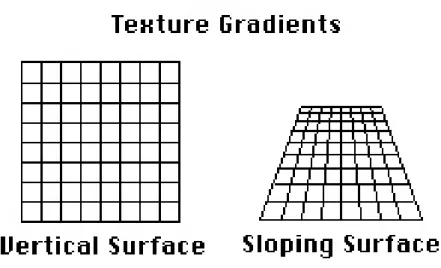
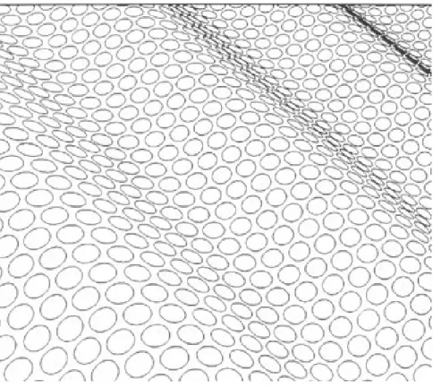
• Texture gradients are the patterns of light formed on the retina from light reflected off textured surfaces, and can give an impression as to the shape or direction of a surface. Texture gradients provide depth cues from the granularity of the texture on the surface. As the depth of a surface increases, so does the texture fineness. Examples of texture gradients providing shape or surface information can be seen in Figures 2.10 and 2.11.
• Haze lightens distant objects and provides depth information for mostly outdoor scenes at large distances.
2.1.3 The Vestibular System
The vestibular system is the non-auditory part of the inner ear labyrinth and interprets head movement and aids balance. The vestibular system is composed of the semicircular canals and the otolith organs, which are located in the utricle and saccule. See Figures 2.4 and 2.5.
Figure 2.5: The semicircular canals and the utricle and saccule. Notice that three the semicircular canals are orthogonal to each other (Northwestern, 2001b).
Angular acceleration is sensed along the three-axes through the three orthogonal cir-cular structures, called the semicircular canals within the inner ear. See Figure 2.4. The semicircular canals are filled with a liquid calledendolymph and little hairs calledcilia. The cilia are the sensory receptors in the semicircular canals and are embedded in a gelatinous structure called the cupula. As the head turns, the endolymph liquid flows through the three orthogonal canals, and moves the cupula, which stimulates the cilia. The moving cilia send information to the brain. The brain then interprets the person’s movement. See Figure 2.6.
Figure 2.6: Acceleration in a semicircular canal (NASA, 2003).
2.1.4 The Interaction of the Visual and Vestibular Systems
The otolith organs and the semicircular canals detect head motion and convey head motion to the brain as neurological signals. Studies from aircraft simulation (Young, 1967; Young et al., 1969) have led to mechanical systems that can model the vestibular sensors. Figure 2.8 shows, as a function of time, simulation results for the relative response to the visual cues of motion, vestibular cues of motion, and the combination of both visual and vestibular (Borah et al., 1979). For a constant stimulus, the vestibular cues are initially dominant, however over time the visual cues become dominant.
Figure 2.7: The figure shows an otolith membrane with cilia and otoconia crystals. “Forces acting on the head and the resulting displacement of the otolithic membrane of the utricular macula. For each of the positions and accelerations due to translational movements, some set of hair cells will be maximally excited, whereas another set will be maximally inhibited. Note that head tilts produce displacements similar to certain accelerations” (Sinauer Associates, 2001).
visual system is dominant. As head angular velocity increases, vestibular dominance in-creases.
The implication for this work in redirection is that when people turn their heads, the vestibular system dominates and visual manipulation may go unnoticed (Figure 2.9). Redi-rection is imperceptible because when people turn their heads at normal angular velocities, the vestibular system dominates the visual system. This enables the VE designer to rotate the VE visuals without the user noticing.
2.1.5 Other Sensory Systems
Figure 2.8: The contribution of the visual and vestibular (inertial) senses, in the time domain, to the perception of a step in rotational velocity (about the yaw axis) (adapted from Borah et al., 1979).
Kinesthetic System The kinesthetic system senses the movement of muscles, tendons, and joints.
Somatosensory System The somatosensory system includes all the body senses from the skin, muscles, joints, and internal organs. The somatosensory system includes the kinesthetic system but does not include the vestibular, visual, auditory, or taste and smell. It is comprised of senses from cutaneous, muscle, and joint receptors.
Proprioceptive System Proprioception is the internal sense of body position and move-ment, and includes the kinesthetic and vestibular senses.
2.2
Visual Perception
Figure 2.9: The visual-vestibular crossover. This graph shows, in the frequency domain, the relative contributions of visual and linear vestibular cues to postural stability (adapted from Duh et al., 2004) .
visual and kinesthetic systems.
2.2.1 Gibson’s Theory of Perception
James Gibson began studying perception in WWII to predict successful and unsuccessful pilots based on the pilot’s capability to decipher depth from images. His findings guided his theory that the observer’s current evaluation of “depth” and “space” perception should be studied through the perception of textures on surfaces. Gibson claims that the structure of light produced by surfaces provides information for visual perception; visual perception is not just light waves stimulating the retina to enable people to “see”, as described in Section 2.1.1.
Gibson’s theory that texture gradients, the structure formed on the optic array from light reflecting off textured surfaces, can give an impression of the shape or direction of a surface. Examples of structure from texture can be seen in Figures 2.10 and 2.11. The structure from texture theory was further verified by (Beck and Gibson, 1955), who found that changing the texture gradient on a plane changes perceived slope of the plane.
Figure 2.10: Applying different textures makes the surface appear to be vertical or sloping. (Redding, 2000)
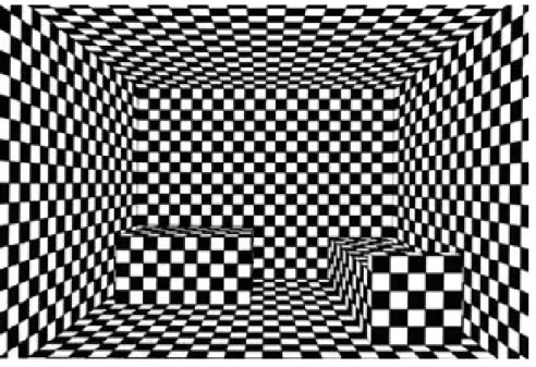
gradients are invariants on the optic array, implying that properties of texture gradients do not change even if the world conditions change, an object will always occlude the same amount of a texture no matter its distance from an observer. The textured surface in Figure 2.12 informs us that the box on the left is farther away than the box on the right.
Gibson believed that the structure of the light reflecting from textured surfaces is re-quired for perception. An example of this is in a Ganzfeld experiment (Metzger, 1930; Gibson and Dibble, 1952; Gibson and Waddell, 1952), where ping-pong balls are placed over participants’ eyes. Although light is reaching the eyes, there is no structure to the light and participants’ cannot perceive their surroundings. This is an example of the dis-parity between the physics of optics and the psychology of perception because texture is needed to perceive objects. Light hitting the eye without texture enables a person to “see,” however they will not perceive.
2.2.2 Vision and Locomotion
Figure 2.11: The texture causes the image to appear to have a ripple shape (Wiersma, 2007).
for visual perception. As people move, the views of the surroundings change, and informa-tion about the layout of the environment and the shape of surfaces, as well as their relative position within the environment, are revealed.
The impression of self-motion, known as vection, can be produced by visual stimulation alone. Vection can occur when a person is sitting in a stationary car and the adjacent car starts to move, causing the person to perceive a sensation of backwards motion.
Figure 2.12: The texture provides information about depth, size, and orientation of the boxes (Schouten, 2003).
Gibson (Gibson, 1979), describes the important relationship between locomotion and optic flow as,
1. Locomotion is specified by flow of the ambient optic array, structured light that reaches the viewer, while stasis is specified by the absence of flow;
2. The type of locomotion is specified by the optic flow such that outflow is an approach, inflow a retreat;
3. The center of expansion of outflow specifies the locomotion direction;
4. A change in thecenter of expansion specifies a change in direction;
Figure 2.13: A. Outward radial optic flow. B. Lamellar, or horizontal optic flow.
the environment which changes the radial or lamellar optic flow (Figure 2.13) presented to the participant. The studies and results are discussed in Section 2.2.3.
Optic flow is represented as an instantaneous velocity field with vectors corresponding to the optical motion of points in the environment. The translational component of optic flow is produced by an observer “translating” forward or backward in the environment, thus producing a radial flow pattern on the retina (Figure 2.13, A). The rotational component of optic flow occurs when the eye or head rotates, which produces a lamellar flow pattern (Figure 2.13, B). In addition to the flow caused by translation and rotation of the body and head, the eyes rotate (Gibson, 1950) which adds additional retinal optic flow. The decomposition of the flow on a person’s eyes into rotational and translational information provide information about the person’s locomotion, however the added optic flow from eye rotation makes decomposition non-trivial.
The next section presents results of studies exploring the relationship between optic flow and locomotion.
2.2.3 Perception and VEs: Studies that Guide Large-Scale Real-Walking
Interface Design
Numerous studies have explored the relationship between vision and locomotion by manipulating the optic flow or visuals presented to the user. Although these studies are important in understanding the connection between vision and locomotion, they also provide additional evidence supporting the capability of visual manipulation in VEs to redirect users. These studies also suggest guidelines for potentially successful techniques. In this section, it is assumed the reader has some understanding of how Redirection and RFED work (Chapter 4).
Figure 2.14: Based on an image from (Bruce et al., 2003). A. The room swings toward the subject causing outward optic flow. The participant interprets the optic flow as if he is moving forward and compensates by leaning backward. B. The room swings away from the subject causing inward optic flow. The participant interprets the optic flow as if she is moving backward and compensates by leaning forward.
flow, to compensate the child should lean backward. This result suggests that radial optic flow should not be imperceptibly manipulated for a stationary standing user because the user may unknowingly lean forward or backward.
(Lee and Lishman, 1975) describes participants in the “swinging room” experiments as “visual puppet(s)” whose balance is manipulated by imperceptibly moving the surroundings around the user. Results from “swinging room” experiments suggested that redirection (Razzaque, 2005) and other VE techniques that manipulate optic flow, such as seven-league boots and motion compression, will be able to redirect user motion as you would a puppet. (Bardy et al., 1996) investigated the role of vision on posture by having participants walk on a treadmill while the experimenters manipulated optic flow and motion parallax on surrounding walls. Participants were found to sway with the optic flow images, however manipulation of motion parallax had a greater effect than manipulation of simple horizontal flow. Their results suggest that people use vision to stay upright, and use motion parallax and optic flow to adjust their bodies. The result that motion parallax has a greater effect suggests that when manipulating optical flow in a VE, a detailed 3D environment should be used, so that motion parallax cues are present.
suggesting that increased optic flow will have an effect on users.
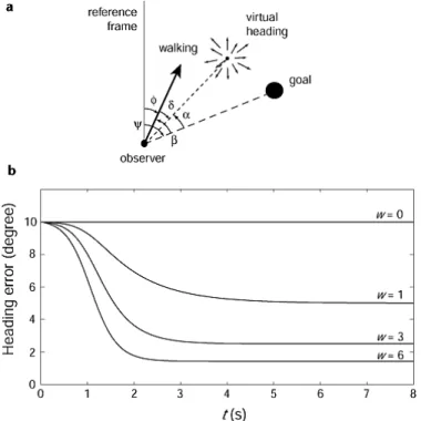
In addition to controlling walking speed and posture, vision also guidesheading direction, the user’s forward direction of motion. Gibson’s theories suggest that heading is determined from the center of expansion of optic flow. When people walk toward a target, they adjust their movements to align heading direction with the intended goal.
Figure 2.15: Left. As the person looks directly along the heading vector, optic flow radiates outward from the center of vision. Right. A prism is placed in front of the eye which shifts the visual location of the goal and the location of the radial optic flow. The optic flow on the retina is the same pattern as on the left but shifted due to the prism. Based on an image from (Rushton et al., 1998).
in front of their eyes. The prism translates not only the target object, but also the optic flow produced when the participant walked toward the target. See Figure 2.15. If the optic flow theory were true, subjects would walk straight to the target because the center of expansion of the optic flow will radiate from the heading direction. However, participants walked along a curved path with the heading direction deviating from the target by approximately the angle of the prism glasses that the participants wore. This suggests that the perceived location of objects guides locomotion direction, and not optic flow.
A study from (Harris and Carre, 2001) suggests that the restricted field of view (FOV) caused by wearing the prism glasses in (Rushton et al., 1998) prevented the use of optic flow in participants’ peripheral vision. Optic flow in peripheral vision guides walking direction (Warren and Kurtz, 1992). When participants wear an HMD, the FOV restricts peripheral vision and therefore heading cannot be guided with peripheral vision. For future RFED development with a wide FOV, optic flow may dominate and redirection may not work as well. Further study evaluating the impact of FOV on redirection may show that changes in optic flow in the peripheral vision guide heading.
Another result supporting the theory that redirection may not work as well in wide field-of-view HMDs is work done examining the importance of radial and lamellar flow in determining heading direction. Results from (Crowell and Banks, 1993) suggest that people are more accurate at determining heading from radial flow than from lamellar flow. Additionally, according to (Warren and Kurtz, 1992), lamellar flow is only used to determine heading in the periphery. VE rotation around the user will affect lamellar flow. HMDs without a wide FOV do not provide peripheral vision. Since lamellar flow is only used to determine heading in the periphery, and radial flow in the center of vision guides heading, rotation of the VE around the user should not alter heading direction.
use the egocentric direction hypothesis to steer to a goal; however, when placed in the same condition with virtual displacement of optic flow, used a combination of egocentric direction and the optic flow theory, with “increasingly dominant behavior” toward the optic flow hypothesis when more optic flow was added to the scene. See Figure 2.16.
(Warren et al., 2001) further investigated whether the egocentric direction hypothesis or the optic flow hypothesis dominates. (Warren et al., 2001) had people walk through virtual environments with different amounts of optic flow (Figure 2.16) to see if the amount of optic flow affected participant heading direction to a target. Their results show that with no optic flow participants followed the egocentric direction hypothesis, however when optic flow was added to the ground plane, participants initially followed the egocentric direction hypothesis, and then after traveling a few meters participants adjusted their heading and used optic flow to aid their guidance.
Figure 2.16: The four environments used in (Warren et al., 2001) with different amounts of optic flow. A. a target line,B.a target line and textured ground plane,C.a fully textured environment with a doorway, D. a fully textured environment with doorway and posts. Based on an image from (Warren et al., 2001).
dθ/dt=−k(β+wvα) (2.1)
where the turning rate (dθ/dt) is a sum of egocentric direction and optic flow. In an extrinsic reference frame, θ represents the walking direction and β is the egocentric direction to the goal. α is the visual angle between the “center of expansion” and the goal, w is a measure of the magnitude and angular area of flow presented to the optic array and due to environmental structure, v is the observer’s velocity, and kis a turning rate constant. See Figure 2.17.
Figure 2.17: Heading error as a function of time and amount of optic flow. An image from (Warren et al., 2001).
Simulations of Equation 2.1 were consistent with results from experimentation (Warren et al., 2001). When optic flow is zero (w = 0) then the turning rate is controlled by β, the egocentric direction of the goal. As optic flow increases (w > 0), the turning rate is controlled by α, the angle between the “center of expansion” and the goal.
in-creases, so does reliance on optic flow for locomotion. All environments used in the RFED studies presented in this dissertation have been fully textured (w >0), providing optic flow throughout the environment. From Equation 2.1, w >0 and therefore α, the visual angle between the “center of expansion” and the goal, controls turning rate. Based on Equation 2.1, when w = 0, a non-textured environment, people rely on the egocentric direction hy-pothesis, and will walk toward redirected targets. This suggests that RFED will work with textured and untextured environments. Further study of RFED altering amounts ofwmay provide insight about different amounts of rotation that can be added to the VE during redirection. Further research should explore the importance of textures on RFED.
2.2.4 The Dorsal and Ventral Streams: Vision for Action and Vision for
Perception
Vision is responsible for two independent functions: the control of action and the “construc-tion of conceptual representa“construc-tions” (Goodale and Milner, 2004). The brain has two separate visual systems, one system controls and guides action, and the other is for perception, the two separate functions of vision. (Ungerleider and Mishkin, 1982) studied the visual sys-tems of monkeys, whose visual pathways and visual syssys-tems are similar to humans. They found that signals from the eyes first reach the visual cortex, a small area at the back of the cerebral cortex. The signal, thedorsal stream, is routed along thedorsal visual pathway
and sent to the posterior partial region at the top of the cerebral hemisphere. The ventral stream, sent along theventral visual pathway, is sent to the inferiotemporal region, located on the bottom and sides of the cerebral hemisphere. See Figure 2.18.
Figure 2.18: The ventral and dorsal streams. Based on an image from (Zuj et al., 2004).
CHAPTER 3
Virtual Locomotion
RFED is first and foremost a virtual locomotion interface for walking through large-scale virtual environments. In this chapter I define locomotion interfaces and discuss commonly used interfaces for walking through virtual environments. I present some of the challenges of using different locomotion interfaces and discuss some of the metrics used to evaluate locomotion interfaces, specifically navigation and simulator sickness.
3.1
Locomotion Interfaces
3.1.1 Introduction
Locomotion, the act of moving from one location to another, is often performed in the real world by walking, running, or crawling, or by transport on a vehicle. To enable locomotion
Figure 3.1: A visual representation of motion interfaces for virtual environments.
does not need to provide significant amounts of self-exertion (Durlach and Mayor, 1995). Passive motion interfaces can further be divided into inertial, where the user is physically moved as in flight or driving simulators with motion platforms, and non-inertial, where the user is not physically moved, as in joystick interfaces (Hollerbach, 2002) and vehicle interfaces without motion platforms. Figure 3.1 visually displays the relationship among different motion interfaces.
I limit the discussion of motion interfaces to those that simulate the act of walking within VEs, because RFED is a locomotion interface for walking between virtual locations. The goal of such motion interfaces is to enable people to perform tasks in the same way in a VE as they would in the real world environment. Examples of these tasks include maneuvering around obstacles, navigating (Section 3.3), or estimating the size of the environment or how far the user has traveled. Research suggests that stimulation of the kinesthetic and proprioceptive systems (Section 2.1.5) aid in representing real walking (Ruddle and Lessels, 2009).
3.1.2 Joystick
Joysticks, a form of passive motion interface, such as the one shown in Figure 3.2, are common interactive devices used to control user POV through VEs. Joysticks are commonly used because they are inexpensive, easy to implement, and can be used in small areas. Joysticks have a base resting position and the joystick is then deflected from that position. The deflected directions on the joystick are mapped to directions in the VE. Some joysticks are isometric, and do not move but sense the user’s forces. In some interfaces, the joystick controls forward speed while direction is controlled by the user’s body or head direction.
reason why people underestimate virtual travel distance (Witmer and Kline, 1998). Ad-ditionally, joysticks are limited in the feedback they provide users about their speed or distance traveled in the environment. Motion feedback through joystick interfaces is pro-vided throughvection, the impression of self-motion produced by visual stimulation alone. Joysticks are also limited in that they do not require user physical exertion, which may be important for training applications. Joystick users traveling a mile in a VE exert almost no energy, unlike users using walking-like interfaces.
Figure 3.2: An xBox 360 game controller. The arrows point to the two joysticks on the controller. This joystick was used in the study described in Chapter 7.
3.1.3 Walking-in-Place
The walking-in-place (WIP) locomotion interface can be thought of as a gestural interface
where gestures are interpreted and control user speed and heading direction. WIP interfaces use the gesture of moving the feet and knees up and down as if the user is walking in place. The “walking” gesture is detected by the system through tracking of the foot, knee, or head movement and is translated computationally into VE motion. Since the person is walking in one location, little space is needed to implement a WIP system.
and gaze direction. A hand-held joystick provides easy steering but limits the ability to carry props. An advantage to using gaze or torso directed steering is that it requires users to physically turn, which stimulates the kinesthetic system.
WIP systems have an advantage over joystick interfaces because users of a WIP sys-tem have feedback from their kinesthetic syssys-tem (Section 2.1.5). A disadvantage of WIP interfaces is that users have to wear extra equipment on their feet or legs for tracking of their steps. This encumbrance is however often considered less important than the benefit of kinesthetic stimulation.
WIP systems are promising interfaces in that physical exertion is translated into virtual motion, they stimulate the kinisthetic system, and they can be implemented in small track-ing areas. However, current WIP implementations do not accurately map user starttrack-ing and stopping gestures into starting and stopping virtual motions (Wendt et al., 2010). WIP systems require walking-in-place some fraction of steps before the system registers walking. WIP systems do not immediately register when the user stops walking-in-place, causing additional virtual motion after real motion stops, a disturbing lag. A fundamental reason for the stopping lag is that there are no stopping gestures to map. Also, even though WIP interfaces stimulate the kinesthetic system, there are discrepancies in the proprioceptive system because users see forward motion however they are not physically moving forward. Treadmills and omni-directional treadmills have this similar problem to WIP interfaces, however treadmills enable the correct walking muscle sensations.
3.1.4 Treadmills
comparable to turning in the real world.
To enable more accurate physical turning, omni-directional treadmills (ODTs) have been developed. ODTs enable users to walk in any direction while remaining in a confined location, however ODTs are loud, expensive, and diminish friction between foot and ground. Users must wear safety harnesses to stay upright. See Figure 3.3. Although treadmills mimic real walking more accurately than WIP systems, they do not provide the same proprioceptive sensations as real walking because people do not physically move forward. Users often have to re-acclimate to real walking after being on the treadmill for extended periods of time (Darken et al., 1997).
Figure 3.3: A soldier positioned on omni-directional treadmill, inside of CAVE environment. (ARL HRED, 2006)
3.1.5 Real-Walking Interfaces
A locomotion interface that enables users to really walk has to restrict the scope of the walking to the tracked space. Current locomotion interfaces that enable real walking in large-scale VEs apply transformations, such as rotating the VE, or scale user motions. However each interface has limitations.
3.1.5.1 Scaled-Translational Gain
An problem with scaled-translational gain is that scaled user motion is not limited to only heading direction. As people walk their heads move side to side (Hicheur et al., 2005). By scaling all motion, the head bobs will also be scaled causing the viewpoint to sway (Interrante et al., 2007).
3.1.5.2 Seven League Boots
Seven league boots improves upon scaled-translational gain by eliminating the viewpoint sway by scaling only user motion in the intended direction of travel (Interrante et al., 2007). This still leaves head bobs in the to and fro direction. The Seven League Boots interface approximates the user’s intended direction of travel by using a weighted average of gaze direction and previous displacement over a short period of time, such as two seconds (Interrante et al., 2007).
3.1.5.3 Motion Compression
Motion compression (MC) (Nitzsche et al., 2004; Su, 2007), has a misleading name because it does not compress motion. Instead, MC rotates the VE around the user and remaps areas of the VE that were outside of the tracked-space into the tracked space. The MC algorithm predicts a user’s future target location based on points of interest in the VE. The algorithm then maps the straight line of the path from the user to the predicted target location into the largest possible arc that can fit into the tracked space. MC continuously updates the target location and the rotation of the VE relative to the tracked space. However, MC does not make imperceptibility of rotation a primary goal. This may increase the likelihood of simulator sickness (Section 3.2).
3.1.5.4 Redirected Walking
future path back into the tracked space. Unlike MC, RDW was designed to make rotation imperceptible to the user. RDW achieves imperceptible rotation by exploiting the visual-vestibular crossover (Section 2.1.4). The visual-vestibular system is dominant over the visual system at head frequencies greater than 0.07 Hz causing users to not perceive unmatched VE rotation while turning their heads at frequencies greater than 0.07 Hz. For this reason, an integral part of the design for RDW was to make users turn their heads frequently.
Razzaque added waypoints to his environments and tasks, predefined locations that defined the user’s virtual route within the VE, for two reasons.
1. A series of waypoints predefined the sequence of the user’s future locations. Knowledge of the user’s future location enables the system to always know what part of the VE should be rotated in the tracked space.
2. Waypoints are a mechanism designed to make people look around. That is, users were required to turn their heads to find the next waypoint. This enabled RDW to rotate the VE and redirect the user’s future path, the path to the next waypoint, into the tracked space.
Although waypoints enable RDW, they limit applications to those that have predefined paths and task related reasons for users to turn their heads.
3.1.6 Reorientation Techniques
Reorientation techniques (ROTs) handle the situation when large-area real-walking tech-niques fail and the user is close to walking out of the tracked space. Additionally, ROTs should interfere the with the virtual experience as little as possible. Each of the methods described in Section 3.1.5 uses a ROT. When users are close to walking out of the tracked space ROTs must stop the user and rotate the VE around her current virtual location. The rotation of the VE places the immediately expected user path back within the tracked space. The user must also reorient herself by physically turning around in the real environment so she can follow her desired path in the newly-rotated VE.
user-worn headphones, that asks the user to stop, turn her head back and forth, and then continue walking in the same direction. Razzaque asked users to turn their heads back and forth because the user is least likely to notice extra rotation while she is turning her head. The ROT used in motion compression (Nitzsche et al., 2004; Su, 2007) is built into the motion compression algorithm: as the user approaches the edge of the tracked space, the arc of minimum curvature is quite small and the VE rotation is large. Large VE rotation causes the user to feel that the VE is spinning around (Nitzsche et al., 2004).
Williams et al. explored three ”resetting” methods for manipulating the VE when the user nears the edge of the tracked space (Williams et al., 2007). One technique involves turning the HMD off, instructing the user to walk backwards to the middle of the lab, and then turning the HMD back on. The user will then find herself in the same place in the VE but will no longer be near the edge of the tracked space. The second technique turns the HMD off, asks the user to turn in place, and then turns the HMD back on. The user will then find herself facing the same direction in the VE, but she is facing a different direction in the tracked space. Preliminary research (Williams et al., 2007) suggests that the most promising is a third technique which uses an audio request for the user to stop and turn 360◦. The VE rotates at twice the speed of the user and stops rotating after a user turn of 180◦. The user is supposed to reorient herself by turning only 180◦ but should think she has turned 360◦. This ROT attempts to trick the user into not noticing the extra rotation, however when testing this ROT I noticed that few participants were tricked into thinking they turned 360◦ after only turning 180◦.
In Chapter 5, I introduce a new ROT, distractors, objects or sounds to which the user attends while the VE rotates. In Chapter 4, I discuss two distractor implementations: one using distractors as ROTs, and one using distractors to prevent the user from reaching the edge of the tracked space.
3.2
Simulator Sickness
dizziness. There are three common theories for the cause of simulator sickness: thesensory conflict theory, the poison theory, and theecological theory.
The sensory conflict theory is the most widely accepted simulator sickness theory (Stanney, 2002), claiming that sickness results when there is a conflict between the sensory systems (Section 2.1). An example of the sensory conflicts within a VE occurs when vection is used to simulate motion. The visual system is stimulated as if the user is moving, however it may be that neither the kinesthetic nor vestibular systems are stimulated. A common argument against using redirection is that there will be conflict between the visual and vestibular sensory systems, since the user’s physical rotations are not mapped 1-1 with the VE rotation. An argument against the sensory conflict theory is that simulator sickness is not always induced when there is a cue conflict. This has led to the development of other explanations.
The poison theory suggests that motion sickness was an evolutionary response that would remove poison from the body (Treisman, 1977). When a body ingests poison, the response is to vomit to remove the poison from the body to minimize further poison induced damiage. (Treisman, 1977) suggests that motion is an artificial stimulus that stimulates a response similar to the neurological stimuli produced by digesting poisonous toxins.
The ecological theory suggests that the interactions between an animal and the envi-ronment are critical to simulator sickness, and the longer an animal is unstable the greater the simulator sickness (Stanney, 2002). The body must work to maintain balance and if we are not balanced, we compensate to try to regain our balance. For example, in a VE, if a user is virtually moving while physically standing still, she may lean in the direction of motion because she thinks she is physically moving, thus causing herself to become unbal-anced. The ecological theory helps explain why some people get sick in VEs while others do not. People who learn to “balance” in VEs by physically responding in a different way to visual stimuli can get their “sea legs” as can sailors on a moving boat.
the work in this dissertation, the Simulator Sickness Questionnaire (SSQ) (Kennedy et al., 1993) was used. The SSQ and an explanation about how to calculate a user’s simulator sickness are in Appendix A.3.
3.3
Navigation
Navigation is a common task in the real world; it is what people physically and cognitively do to get from point A to point B. People navigate everyday without problem, yet in virtual worlds people often get frustrated and lost (Durlach and Mayor, 1995; Psotka, 1995; Darken and Sibert, 1996; Grant and Magee, 1998). Navigation is a fundamental task for exploring large environments and enabling people to navigate with equivalent ability in a VE and the real world should be a high priority for an interface designer. Enabling equivalent navigation in VEs and the real world will expand the usefulness and types of applications for which VEs can be used.
Designing a VE interface that enables successful user navigation requires an under-standing of how people navigate in the real world. Navigation is cognitive and physical and is defined as the combination of wayfinding and locomotion (Darken and Peterson, 2002). Wayfinding, the cognitive part of navigation, is a constantly updating mental pro-cess determining how to get from one location to another. Locomotion is the physical part of navigation and is the act of moving between two locations. Locomotion interfaces are discussed in Section 3.1.
The cognitive part of navigation, wayfinding, is associated with building and exploiting a mental map (Darken and Peterson, 2002). When people explore environments, real or virtual, they build a mental map of the environment. Mental map building is dependent on many factors and is related to the user’s natural ability to navigate. When people locomote around an environment, they begin building a mental map. The fidelity of the mental map improves over time and through multiple exposures to an environment. However, even in the real world, people often develop inaccurate mental maps of the environment even after years of exposure (Waller et al., 1998).