112
Abstract— As the population is escalating with an alarming
rate, the numbers of vehicles are also increasing simultaneously with a rising rate in road accidents. Most probably, the accident occurs in the blind curve. The paper provides the collision anticipation warning alerts to the vehicle’s user in order to avoid the accidents. As all are becoming techno-savvy, vehicles should not remain back. For this purpose we have suggested a system that performs V2I communication and I2V communication for V2V communication.
The vehicles should be comprised of an On Board Unit (OBU) consisting of AVR kit and RF sensors for communication with other vehicles via Road Side Unit (RSU). The RSU also encompasses temperature sensor and LDR. The surrounding vehicles of RSU will get the information of the temperature and weather condition in terms of hot, pleasant and cold climate. This enhances the Intelligent Transportation System (ITS) by providing Advance Driver Assistance and In-Vehicle information.
The paper is focusing on the technology of Wireless Access in Vehicular Environment WAVE i.e. IEEE802.11p with wireless sensor nodes creating wireless sensor network. The results are shown in terms of emulation with the help of AVR kits and RF sensors. Also the numbers of accidents are recorded from RSU and shown graphically.
Index Terms— blind curves, ITS, WSN, WAVE.
I INTRODUCTION
Research in Intelligent Transportation System (ITS) has become one of the hot topics among all researches. Many features are getting added to the vehicles in order to provide assistance to the users. ITS focuses on applications like collision warning alerts, climate information, in car signage, situational awareness, parking lot information, advertising of roadside business, car to car messaging or voice, vehicle population diagnostics and many more.
With the growth in technology, people are becoming techno-savvy and want everything to be automatic. ITS enhance the needs of people by providing technological aid to the vehicles. In this paper we are proposing a system which
Manuscript received 20 May, 2012.
Ms. Prachi P. Jaini,, Computer Science and Engineering, G.H.Raisoni College of Engineering Affiliated to Rashtrasanth Tukdoji Maharaj Nagpur University., Nagpur, India,
Ms. Nikita A. Chavhan, Computer Science and Engineering, G.H.Raisoni College of Engineering Affiliated to Rashtrasanth Tukdoji Maharaj Nagpur University., Nagpur, India.
makes use of Wireless Access in Vehicular Environment WAVE i.e. IEEE802.11p with wireless sensor nodes creating wireless sensor network to assist the ITS standard.
Transportation is a sector of major concern in any country in relation with the increasing demand of population growth. The World Health Organization has revealed in its Global Status Report on Road Safety that more people die in road accidents in India than anywhere else in the world, including the more populous China. Bad infrastructure and rash driving are the cause of accidents according to WHO report. As road traffic accidents take the lives of nearly 1.3 million every year, and injure 20-50 million more in the world. India, along with China, is listed among countries with the highest number of deaths. Various governmentally funded ITS projects have been launched in many countries like Canada, USA, Europe, Japan, Australia and others [1].
The number of accidents on Indian roads is increasing with every day, despite concrete laws and penalty levied on breaking road rules. In fact, with latest figures of 1,05,000 annual deaths due to road accidents, India has overtaken China. The report also says that over 90% of road traffic deaths and injuries occur in low-income and middle-income countries, which have only 48% of the world's registered vehicles. Global estimates show that nearly 3,500 people die on the world‘s roads every day and tens of millions of people are injured or disabled every year [2].
Now days, road accidents are happening due to blind curves, foggy weather etc. We are proposing a solution to remove this problem by providing alerts to avoid collision.
The remainder of this paper is organized as follows. In Section II we first introduced a brief overview of the Technology, Section III covers literature survey, Section IV covers system composition, Section V consists of frame format, and Section VI consists of CAWS Algorithm and Section VII consists of emulation result. Finally we conclude the paper in Section VIII.
II TECHNOLOGY OVERVIEW
In this paper we are using three standards namely ITS, WAVE standard and Wireless Sensor Network. Intelligent Transportation System (ITS) refers to the efforts that add information and communication technology to transport infrastructure and vehicles. ITSs are a state of art, which is
Accidental Warning System in WSN using
WAVE to Avoid Collision
Volume 1, Issue 3, May 2012
the combination of transportation infrastructure, computer and information technology. ITS manage factors like vehicles, loads and routes to improve safety, traffic congestion and emergency conditions like major accidents. ITS is not restricted to Road Transport - they also include the use of information and communication technologies (ICT) for rail, water and air Transport including navigation systems.
Various ITS subgroups are [3], [a] DAS [Driver Assistance Systems]: E.g. Antilocking Brake Systems [b] ADAS [Advanced Driver Assistance Systems]: E.g. dynamic route-guidance systems and blind-spot warning systems. [c] IVIS [In-Vehicle Information Systems]: E.g. static route-guidance systems, mobile phone, Internet, weather warning systems [d] IVDS [In-Vehicle Data Collection Systems]:E.g. accident/event data recorder (ADR/EDR), eCall, fleet management systems, and dynamic route guidance systems. e] RT [Roadside Telematics] [4]: E.g. GPS, Anti-theft, Automatic collision avoidance system, Multimedia entertainment, Variable message signs (VMS), Collective feedback of speed and Electronic stability control (ESC). Figure 1 gives the overview of the various types of Information Transportation system.
In our proposed system we are providing a) Advanced Driver Assistance by conveying location and collision anticipation warning alerts in terms of display and buzzer, b) In – Vehicle Information by providing climate condition and c) In Vehicle Data Collection by displaying the number of accidents recorded by the road side unit in terms of graph. Wireless sensor networks are usually composed of small, low-cost, devices that communicate wirelessly and have the capabilities of processing, sensing and storing. WSN can use some wireless technologies such as Bluetooth, Zigbee, Wireless LAN, WiMAx and 3G [1]. In our proposed system, RF sensors are used for vehicle to infrastructure (V2I) and infrastructure to vehicle (I2V) communication. This communication creates the vehicular adhoc network.
IEEE 802.11 standard is a non viable solution for a vehicular environment. To better cope with the dynamic nature of V2V and V2I links, the IEEE 802.11p has been proposed as a draft amendment to the IEEE 802.11 standard. The IEEE 802.11p task group is currently working on a set of specifications to permit communications in the rapidly changing vehicular environment, which operates in the DSRC (Dedicated Short Range Communication) frequency band (5.85-5.925 GHz) [6]. IEEE802.11p is a part of DSRC, it deals essentially with the data link and physical layer of the OSI model [7].
In our proposed system we are using IEEE802.11p standard for the wireless communication among the vehicles using the RF sensors of frequency 433MHz covering 100m of range.
Figure1. Overview of ITS [5]
III LITERATURE SURVEY
Automotive Research Testing Center (ARTC, Taiwan) established embedded on-vehicle imaging system. It uses DSP (digital signal processor) to capture image signal from CCD (Charge Coupled Device) or CMOS (Complementary Metal Oxide Semiconductor) image sensor, steering wheel and speed signal of vehicle from microprocessor. Cameras are installed on two sides of a vehicle to capture the images of blind spots and the driver is alerted to watch the approaching vehicles as driver would like to change the lane.
It integrates RS232 interface to modulate parameter of blind-spot area between computer and microprocessor. ARTC on-vehicle imaging system can be applied to all kinds of detection region. Image entropy estimation method is used to convert the captured image into one dimensional (1-D) distance-axis signal information.
The blind-spot system was verified by using the video database of blind-spot area, including three road situations (high-speed road, urban road and thoroughfare road) and four weather conditions (sunny day, sunny night, rainy day and rainy night) [8]. This can be further improved in Wireless Sensor Network using sensors.
WSN and Bluetooth technology was proposed in [1]. It uses Bluetooth protocol which is used for inter-vehicle communication among vehicles equipped with Bluetooth devices. Vehicles communicate by forming an ad-hoc network and serve the base station so that coming vehicles can use this information. [9] Compares two methods of estimating relevance for the emergency electronic brake light application. One uses an analytically derived formula based on the minimal safety gap required to avoid a collision. The other method uses a machine learning approach. The methods were compared using simulated experiments with a range of traffic and communication parameters.
114 and transmit information that is difficult to collect manually.
This feature is applied to the telematics field to continuously observe the action of a vehicle. The collected information can be used in a service that gives a warning to the driver under certain circumstances.
A service system was proposed that can satisfy the requirements of 1) event driven operation, 2) deployment considering road structure, and 3) routing schemes considering data characteristics. In this application magnetic sensors were used. Magnetic sensors are sensitive enough to detect a vehicle and easy to handle.
A cooperative communication protocol for a Vehicle Collision Warning System (VCWS) for a highway was proposed in [11]. It addresses two problems namely, Detection of endangered vehicles and warning message propagation. Its focus is on designing an efficient message forwarding mechanism. This was implemented only for highways.
The proposed WAVE-compliant MAC Protocol to Support Vehicle-to-Infrastructure Non-Safety Applications [6]. The scheme is fully compliant with the IEEE 802.11p/WAVE (Wireless Access for Vehicular Environment) operational mode. They research on one hop scenarios; however, additional efforts are required to investigate the feasibility of such an approach in V2V multihop communications scenarios, by enabling moving providers‘ coordination and enhancements in the scheduling policy.
VIPER protocol is a vehicle-to-infrastructure communication protocol. The VIPER protocol intuition is to have vehicles not to send their messages directly to the RSU, but to have vehicles acting as mixes [11]. The protocol shows three major traffic analysis attacks: message coding attack, message volume attack and timing attack. The performances of VIPER are only marginally affected by an increase in the number of vehicles.
In [13], a traffic monitoring system is implemented through Wireless Sensor Network (WSN) technology within SAFESPOT Project funded by the European Community. The proposed solution involves a network composed of one Gateway Node (GN) and n Sensor Nodes (SNs) identified by their own address i=1,…,n. The GN is connected to the RSU through a wired interface. A Local Detection Algorithm processing the large amount of raw sensor data to detect possible passing vehicles.
Anisotropic Magneto-Resistive (AMR) sensor and a Pyroelectric (Pyro) sensor are used in each Sensor Board. The AMR sensor measures the Earth‘s magnetic field and, consequently, its variation when vehicles pass by. The Pyro sensor provides accurate temperature measurements.
Summary of Literature Survey
With the assistance of the related literature survey, the system was proposed that provides collision anticipation warning alerts to the vehicles using V2V communication via
V2I and I2V communication. Also climate conditions are known with help of temperature sensor LM35DZ and LDR.
IV SYSTEM COMPOSITION
The system composition of the proposed system consists of the following:
1.Wireless Sensor Nodes
AVR AtMega32 Microcontroller
RF Sensor
Batteries
2. Road Side Unit
AVR AtMega32 Microcontroller
RF Sensor
Batteries
Temperature Sensor (LM35DZ)
LDR
Advanced Virtual RISC is an 8-bit AVR microcontroller. AVR microcontroller executes most of the instructions in single execution cycle. It belongs to the family of Reduced Instruction Set Computer (RISC). Instructions set are simpler and faster in performing operation. AVR microcontrollers are available in three categories as shown in table 1.
In the paper, two vehicles in terms of nodes are considered. For wireless communication, RF sensors are used. Wireless range is about 30 - 40 meters in closed environment and is about 100meters in an open environment. RF communication is working in the frequency range of 433MHz. AVR kit on vehicles get the energy from the vehicle‘s battery i.e. 12 Volt. Data is sent using UART bit transformation.
Table 1: Classification of AVR
AVR Family Description
TinyAVR Less memory, small size, suitable only for simpler applications.
MegaAVR having good amount of memory (upto 256 KB), higher number of inbuilt peripherals and suitable for moderate to complex applications
XmegaAVR Used commercially for complex
Volume 1, Issue 3, May 2012
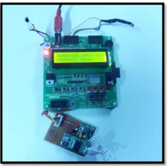
Figure 2: RSU Kit [Control Node]
The RSU is as shown in figure 2 consisting of temperature sensor LM35DZ and LDR. Temperature sensor senses the environment temperature and conveys it to the nodes in its range using I2V communication. Also with temperature sensor and LDR weather condition is also calibrated and provides in-system information to the driver.
LM35 is integrated circuit temperature sensor made by National Semiconductor. The LM35 series are precision integrated-circuit Temperature Sensors whose output voltage is linearly proportional to the Celsius (Centigrade) temperature. The LM35 does not require any external calibration or trimming to provide typical accuracies of ±1⁄4°C at room temperature and ±3⁄4°C over a full −55 to +150°C temperature range [14]. LM35DZ is one of the types of LM35 temperature sensor. The pin function of LM35DZ temperature sensor is as shown in figure 3.
LDR is the Light Dependent Resistor used with temperature sensor to provide in-vehicle information related to weather. The SI unit of illumination of LDR is lux. With the help of LDR weather condition cold, pleasant and hot are known. LDR acts as a light sensor. As the weather condition detection requires both temperature and intensity of Light, LM35 DZ and LDR are used.
Figure 3: LM35DZ temperature sensor's pin function [14]
[A] LDR circuit Symbol [B] Pictorial view of LDR
Figure 4: Light Dependent Resistor
V FRAME FORMAT
The RF channel is unreliable, so there should be a specified format while there is a communication between vehicle and infrastructure. The vehicle will be considered as vehicle node and the road side unit i.e. the infrastructure will be considered as control node. Figure 5 shows the V2V communication via V2I and I2V communication.
[A] Vehicle to Infrastructure Commnunication [V2I]
The V2I frame is of 40 bytes. Whenever vehicle to infrastructure communication is done, the frame format used is
$ VN E EN #
0 7 15 23 31 39
$ - Start bit VN - Vehicle number E - Event
EN - Event type Number
# - Stop bit
The event is the incident taking place while communication between vehicles. The event type number can be 1, 2, 3, 4. The event type number 1 is for location 1, event type number 2 is for location 2, event type number 3 is for location 3 and event type number 4 is for accident.
116
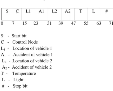
[B] Infrastructure to Vehicle Communication [I2V]
Whenever vehicle to infrastructure communication is done, the frame format used is
$ C L1 A1 L2 A2 T L #
0 7 15 23 31 39 47 55 63 71
$ - Start bit C - Control Node L1 - Location of vehicle 1 A1 - Accident of vehicle 1 L2 - Location of vehicle 2 A2 - Accident of vehicle 2 T - Temperature
L - Light # - Stop bit
VI COLLISION ANTICIPATION WARNING SYSTEM ALGORITHM [CAWS]
The alerts provides assistance to the driver in the blind curve , line of sight problem, lane passover of other vehicle in same lane or opposite. The range of the signals depends on the range of the sensors on the AVR kit. Figure 6 shows the flowchart of Collision Anticipation Warning System working.
Notations:
N1 - Node1 or Vehicle1 N2 - Node 2 or Vehicle 2 C - Control Node
Figure 6: CAWS Flowchart
A. Vehicle to Vehicle Communication
1. ‗C‘ sends 50 frames with frame format
$ C L1 A1 L2 A2 T L # i.e. for I2V communication
2. ‗N1‘ sends 10 frames with frame format $ 1 E EN # i.e. for V2I communication.
3. ‗N2‘ sends 10 frames with frame format $ 2 E EN # i.e. for V2I communication.
4. C‘ receives 100 frames, it decode frames and stores the received data.
5. ‗C‘ sends the ‗N1‘ signals [50 frames] to ‗N2‘ and the ‗N2‘ signals [50 frames] to ‗N1‘.
6. ‗N1‘ receives ‗N2‘ signals i.e. 50 frames and ‗N2‘ receives ‗N1‘ signals i.e. 50 frames. In this way V2V communication takes place.
B. Wheather Information:
Three type of weather information is seen namely Pleasant (P), Cold (C) and Hot (H). Weather information is known with help of temperature sensor LM35DZ and LDR attached with RSU.
Following conditions are applied on vehicle‘s OBU:
C : Light between 0 to 50 and Temperature 0oC to 20oC
P : Light between 51 to 150 and Temperature 21oC to 35oC
H : Light above 150 and Temperature above 35oC
C. Buzzer Alert:
1. When location of vehicle 1 is same as that of vehicle 2 user gets alert from each other through RSU.
2. When accident of vehicle 1 occurs. 3. When accident of vehicle 2 occurs.
D. LCD Display:
Whenever one of the vehicle sends signal to the other vehicle about the location, it first passes to the RSU displaying the location of vehicle on the RSU then passing the signals to the other vehicle and also to the vehicle itself that conveys the signals to the other vehicle.
Considering three keys for locations and one for accident, if vehicle 1 is in location l then it is displayed in the RSU kit and in the other vehicles in its range. Also acknowlegement is seen in the vehicles kit sending the location.
VII EMULATION RESULT
Volume 1, Issue 3, May 2012
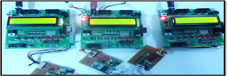
Figure 8 shows the location of vehicle 1 . Figure 9 shows the snapshot
of accident of the vehicle 1. Figure 10 shows the snapshot of location of vehicle 2.
In the figure left side denotes the node1 or vehicle 1 and right side denotes the node 2 or vehicle 2, the central node is the control node or RSU. Initiaally, the location and accident is zero. Whenever the vehicles are in the same location and when vehicles accident occurs, buzzer is activated.
A.EMULATION : GRAPHICAL RESULT
Figure 11 shows the number of accidents recorded by the RSU during V2V communication. The graph is generated for two purposes namely, one for calculating the number of accidents and secondly that the data is forwarded from V2I and then I2V for V2V communication. In order to fetch the data from RSU to the PC, the USB to serial port converter is required.
Figure 7: Snapshot of Initail condition of AVR kit
Figure 8: Snapshot of AVR Kit displaying Location of Vehicle 1 to the Left
118 Figure 10: Snapshot of AVR Kit displaying Acciddent of Vehicle 2 to the Right
Following steps are required for generaing graph:
Record the number of accidents in the RSU at the maximum 100 accidents.
Pass the data into PC by changing the RSU into Data Monitoring mode while pressing key1.
Remove the RF sensor from the RSU and connect it to PC via USB to serial port converter.
Mount MAX232IC on RSU for data transformation purpose.
Run the code and send the data to the PC while pressing the key 2.
Graph is generated.
The code is executed in MATLAB. As the AVR microcontroller is working in 5V, it needs to be converted into
12V for transferring the data into PC, for this purpose MAX232 IC is used.
Figure 11: Snapshot of number of accidents graph
VIII CONCLUSION AND FUTURE SCOPE
In this paper, the system is able to perform location tracking in terms of check point, accident monitoring and specifying weather condition. The system is able to emulate collision anticipation warning alerts in terms of lcd display and buzzer. The system provides alerts when the vehicles are in the range of RSU. Alerts can be provided when vehicles are on the opposite lane, same lane and during the blind curve. Buzzer alerts the driver when the location is same and when accident occurs.
Thus, the system enhances the intelligent transportation system by providing advance driver assistance and in-vehicle information with the assistance of wireless sensor nodes that facilitates wireless access in vehicular environment.
The system can be helpful for future telematics services like vehicle theft identification and vehicle condition control. The system can be used with Zigbee which will increase the range. Also, GPS can be used for location tracking instead of pressing keys.
REFERENCES
[1] Vivek Katiyar, Prashant Kumar , Narottam Chand, ― An Intelligent Transportation Systems Architecture using Wireless Sensor Networks, ‖ International Journal of Computer Applications (0975 – 8887) Volume 14– No.2, January 2011.
[2] Ratheesh Kumara1, Faisel T Illiyasb2 and ShibuK Manic,‖ An investigation on road accident prone curves of national highway 220 in Kottayam district, Kerala‖ , DRVC 2011.
[3] T. Vaa, M. Penttinen and I. Spyropoulou, ―Intelligent transport systems and effects on road traffic accidents: state of the art‖, IEEE 2007.
[4] Yingxue Chen, Peng Yu, Zhigang Liu ―Research on Vehicle Intelligent Communication Based on SuperNetwork System,‖ IEEE 2011.
Volume 1, Issue 3, May 2012
intelligent-transport-systems-its/.
[6] Marica Amadeo, Claudia Campolo, Antonella Molinaro, Giuseppe Ruggeri, ―A WAVE-compliant MAC Protocol to Support Vehicle-to-Infrastructure Non-Safety Applications‖, IEEE 2009.
[7] Mahamat Ahmat Abakar, Rashid. A. Saeed, Aisha A. Hassan, Orner M. Mohammed, Othman Khalifa, and Shayla Islam,‖The challenges of wireless internet access in vehicular environments‖, in IEEE Information and Communication Technology for the Muslim World (ICT4M) on 13-14 Dec. 2010, pp. D31 - D36.
[8] C.T. Chen, Y.S. Chen, ―Real-time approaching vehicle detection in blind-spot area‖, 12th International IEEE Conference on Intelligent Transportation Systems, St. Louis, MO, USA, October 3-7, 2009.
[9] Piotr Szczurek, Bo Xu, Ouri Wolfson, Jie Lin ―Intelligent Transportation Systems: When is Safety Information Relevant?‖, IEEE 2011.
[10] KyungBok Sung, JaeJun Yoo, DoHyun Kim ―Collision Warning System on a Curved Road using Wireless Sensor Networks‖, IEEE 2007.
[11] Huang Zhu, Gurdip Singh, ―A Communication Protocol for a Vehicle Collision Warning System‖, IEEE 2010.
[12] Paolo Cencioni , Roberto Di Pietro, ―VIPER : A Vehicle
-to-infrastructure communication privacy enforcement protocol ―IEEE 2007.
[13] Mirko Franceschinis1, Luca Gioanola, Massimiliano Messere, Riccardo Tomasi1, Maurizio A. Spirito, Pierluigi Civera, ―Wireless Sensor Networks for Intelligent Transportation Systems‖, IEEE 2009.
[14] Cuihong Liu, Wentao Ren*, Benhua Zhang,Changyi Lv ― The application of soil temperature measurement by LM35 temperature sensors ‖, 2011 International Conference on Electronic & Mechanical Engineering and Information Technology.
Ms. Prachi P. Jaini received the B.E. degree in Computer Science and Engineering from G. H. Raisoni College of Engineering, Nagpur University in 2009. Her research work includes wireless communication, wireless sensor network.