AIP Development Process
GEOSS Architecture Implementation Pilot (AIP)
Preface
This document defines the development process employed on the GEOSS Architecture Implementation Pilot (AIP) an element of GEO Task IN-05 “GEOSS Design and
Interoperability”. AIP conducts research and prototyping to recommend improvements to the GEOSS architecture and to generate best practices how GEOSS data and components can be used in scientific workflows outside of GEOSS. AIP develops and pilots new process and infrastructure components for the GEOSS Common Infrastructure and the broader GEOSS architecture.
AIP employs an “evolutionary development process” whereby the architecture, the delivered systems, and the stakeholders co-evolve. Stakeholder needs are reassessed with each iteration of the architecture; the architecture is used to guide each system as it moves through development, and appropriate versions are used to evaluate each system on delivery. The AIP Development process consists of a series of phases, e.g., phase 6 (AIP-8). Major efforts of a phase of AIP are initiated with a Call for Participation (CFP). As an element of the development, AIP has defined a System Design process structured using Scenarios and Use Cases. Scenarios describe how GEOSS is envisioned to support SBA Communities of Practice. Use Cases are reusable transverse technology approaches for implementing the scenarios.
The major deliverable items of development in an AIP phase are:
1) Develop and deploy easy-to-use online (Web and Mobile) apps that demonstrate the value of standards-based access to EO data and services registered with GEOSS and activities to support the key apps.
2) Documentation of the results of the AIP Phase in Engineering Reports regarding the scenarios and technical topics, and
3) Demonstration of the newly developed functionality using the SBA Scenarios and selected technical topics.
This version of AIP Development Process was prepared in tandem with two other AIP documents:
GEOSS AIP-8 Call for Participation, 28th January 2015 GEOSS AIP Architecture, 28th January 2015
The documents are available at this URL:
TABLE OF CONTENTS
PREFACE ... II
AIP DEVELOPMENT PROCESS ... 1
1 OVERVIEW ... 1
2 DEVELOPMENT PROCESS ... 1
2.1 PROCESS OVERVIEW ... 1
2.2 CONCEPT DEVELOPMENT ... 2
2.3 CFP DEVELOPMENT ... 2
2.4 (VIRTUAL)KICKOFF WORKSHOP ... 2
2.5 DESIGN,DEPLOY AND INTEROPERABILITY TESTING ... 3
2.6 DEMONSTRATION ... 4 2.7 TRANSITION TO OPERATIONS ... 4 3 ORGANIZATIONAL ROLES ... 6 3.1 PARTICIPANTS ... 6 3.2 IPTEAM ... 6 3.1 GEOSECRETARIAT ... 6 3.2 OBSERVERS ... 6 4 COMMUNICATIONS PLAN... 7
4.1 DISTRIBUTED COMMUNICATION REQUIREMENTS ... 7
4.2 WEBEX TELECONS ... 7
4.3 E-MAIL REFLECTORS ... 7
4.4 AIP WEB PAGES ... 7
4.5 WORKING GROUP’S WIKI ... 7
4.6 GEOBEST PRACTICE WIKI ... 7
5 PRINCIPLES OF CONDUCT... 8
5.1 GEOSS REFERENCES ... 8
5.2 PRINCIPLES OF CONDUCT ... 8
6 SYSTEM DESIGN PROCESS ... 9
6.1 PROCESS TERMINOLOGY ... 11
AIP Development Process
1 Overview
This AIP Development Process defines the process used in the GEOSS Architecture Implementation Pilot (AIP). The AIP Development Process is a normative reference to the AIP Call for Participation (CFP).
(The process defined in this document was initially defined based upon the OGC
Interoperability Program procedures for a Pilot Initiative. More information can be found here: http://www.opengeospatial.org/ogc/policies/ippp)
2 Development process
2.1 Process overview
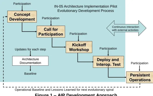
AIP employs an evolutionary development process whereby the architecture, the delivered systems, and the stakeholders co-evolve. Stakeholder needs are reassessed in each iteration of the architecture; the architecture is used to guide each system as it moves through development, and appropriate versions are used to evaluate each system on delivery. Architectures developed under this approach emphasize flexibility and adaptability. This approach is well suited to software system development where it is impossible to postulate all of the requirements and the system development can proceed iteratively. The AIP Development process consists of a series of phases, e.g., phase 7 (AIP-8). Figure 1 shows the steps for a single phase of AIP.
Figure 1 – AIP Development Approach
Deploy and Interop. Test Kickoff Workshop Call for Participation Concept Development Persistent Operations Participation Participation Participation Participation Participation Architecture Documentation Updates for each step
Baseline
IN-05 Architecture Implementation Pilot Evolutionary Development Process
Operational Baseline and Lessons Learned for next evolutionary spiral
Continuous interaction with external activities
2.2 Concept development
The Concept Development phase produces an architecture and plan sufficient for a Call for Participation in the Pilot Initiative. The Architecture is refined based upon the results of previous phases of the Pilot. This feedback is a key to this form of evolutionary development process.
Specific areas of emphasis for a phase of AIP are defined through extensive discussions with the GEO Infrastructure Implementation Board (IIB). AIP also coordinates with GEO boards and with GEO tasks relevant to the content of the phase. The objective is to gather broad input and agreement on the content of the phase with the GEO community.
2.3 CFP development
The second step in the AIP development process is to release a Call for Participation (CFP) and to receive and evaluate responses to this CFP. Once a draft CFP is developed by the AIP Team it is presented to the GEO IIB for their review and comment.
Comments are addressed and incorporated by AIP IP Team into the final version of the CFP. Once the AIP Team and IIB agreed to the release, the CFP is announced through several communication mechanisms, in particular by the GEO Secretariat. The desire is that multiple organizations will respond to the CFP explaining the technical contribution they intend to make, how their contribution maps to the architecture, and the
contributions they will make to the initiatives. On receipt of the CFP responses, the AIP IP Team reviews the responses, updates the architecture and plans for the Kickoff Workshop.
2.4 (Virtual) Kickoff Workshop
Organizations that respond to the CFP will want to attend the Kickoff Workshop March 23, in Norfolk VA, USA (http://www.gstss.org/2015_Norfolk_4th/)– facilities for remote participants will be made available (details to be send out to the participants prior to the meeting). This allows the participants to meet in-person or virtual to plan the pilot as all subsequent activities are conducted using distributed communication mechanisms. All responding organizations can assume their responses are accepted for participation in the Pilot unless they are notified otherwise. The IP Team will work with the AIP Team and Initiative Sponsors to develop an agenda for the Kickoff Meeting.
During Kickoff workshop a development plan and schedule that defines specific milestones will be confirmed.
The Kickoff Workshop will address: (1) component definition and (2) scenario development. These development activities interact and affect each other. At the Kickoff Workshop, there will be meetings to begin developing component solutions. The participants are expected to have systems and/or software engineers in attendance to assist in the initial assessment and interaction of Interoperability Arrangements. Use cases will be developed for organizations to consider in their component design. As a way of validating the use cases and interoperability arrangement, they will be analytically “exercised” against the scenarios.
Simultaneously at the Kickoff Workshop, there will be breakouts to begin scenario design and creation. This activity will involve the development of use cases to implement
the scenarios. Discussion of needed data and coordination with involved communities will be needed to ensure the validity of the scenario development.
A result of the Kickoff Workshop is establishment of Working Groups (WGs) for SBA and technical topics. Volunteers to lead the WGs are determined.
2.5 Design, Deploy and Interoperability Testing
Deployment and Interoperability Testing begins after the Kickoff Workshop and includes the elements of System Design, Component Deployment and Testing activities.
Development activities occur in both WG and Plenary groups.
Using results of the Kickoff Workshop as the governing documents for the conduct of the initiative, the participants will begin the principal tasks of refining engineering
specifications as needed, developing components, and testing those components. The key outcome of the pilot initiative will be persistent, operational exemplar components and demonstrations exercising the components to meet the needs of the SBAs.
The System Design process is structured using Scenarios and Use Cases. Scenarios describe how GEOSS is envisioned to support SBAs. Use Cases are reusable transverse technology approaches for implementing the scenarios. Results of the Design Process include identification of Interoperability Arrangements for components and services that will achieve the objectives of the SBA scenarios and broader architecture. For a full description of the Design process see Section 6.
During the selection of Interoperability Arrangements, modifications to existing open standards specification may be found to be necessary, then a change proposal must be developed that documents the change. Change proposals do not need be adopted during the pilot; rather it is intended to serve as documentation of both the change and the requirement that led to the change. The change proposal will be submitted to the appropriate standards developing organization (SDO).
Participants can interact with the GEOSS Standards and Interoperability Forum (SIF). The SIF oversees the Standards and Interoperability Registry (SIR). SIF Interoperability Advisors provide technical assistance with questions and decisions regarding
interoperability, including use of standards and special arrangements. SIF representatives participate in the AIP process. Online access to the SIF can be found by going to
http://seabass.ieee.org/groups/geoss.
Use of the Best Practice Wiki (BPW) (See Section 4.6) is encouraged for AIP
participants so that what is believed to be a best practice can be recorded for others to benefit from as they decide to participate in GEOSS. Contributions to the BPW need not be finished best practices, since the BPW can be used during the AIP process to fine tune the content provided.
A primary goal of a pilot is to verify by testing that interaction of a set of components that exercise a set of specifications supports SBA scenarios. AIP Testing is tailored to the specific environment of GEOSS considering that there is not a separate testing team. Testing is done at two levels: 1) unit testing of individual services as defined in
engineering use cases, and 2) integrated testing of SBA scenarios. Testing is organized around two iterations of unit testing followed by a single scenario testing.
Interoperability testing has been recognized as a much needed and useful activity that produced extremely valuable results, with the issue of versioning of services and interfaces experienced in many situations (See AIP-4 Summary ER).
2.6 Demonstration
Demonstrations in AIP communicate to GEO new capabilities developed in the Phase that can be considered for GEOSS enhancements. Some demonstrations do not necessarily result in changes to GEOSS, but show new results based on GEOSS components, data, and services.
Participation in the demonstrations is predicated upon full engagement with development, testing, and planning activities throughout the initiative.
To finalize the demonstrations, a Demo Capture Workshop may be convened to conduct the final integration of the components and to refine the steps in the demonstrations. During the workshop, the demonstrations will be captured through techniques such as client screen capture software. The demonstrations will then be made available for distribution.
Demonstration developers coordinate on the production of the demo videos. Each of the videos is developed based upon a template common to all videos and a storyboard specific to each demo. Videos of the demo are captured and edited with desktop video tools. The complete set of demonstration videos will be packaged with an overall menu and introduction to AIP and made available on the web. In order to reach the broadest audience, demonstrations are made available via the Internet.
2.7 Transition to operations
GEOSS Operations are the responsibility of the GEO Members and Participating
Organizations. GEO Task IN-03 is the focal point for operations of the GEOSS Common Infrastructure (GCI).
Developments accomplished during an AIP Phase are anticipated to persist as through registration in the GEOSS registry ideally with the status of “Continuous Operations.” AIP provides an increase in the baseline of operational components in GEOSS and provides methods to monitor the operations of GEOSS components. AIP does not include the operations of GEOSS.
At the end of an AIP Phase, the results are communicated to GEO broadly with encouragement that the GEO maintain the results achieved. These presentations will inform the various groups of the AIP developments and new functionality that has been developed. It is anticipated that the new functionality will contribute to the advance of the GCI and the broader GEOSS.
The major deliverable items of an AIP phase are:
1) Deployment and registration of components and services that continue to build GCI and the broader GEOSS,
2) Documentation of the results of the AIP Phase in Engineering Reports regarding the scenarios and technical topics, and
3) Demonstration of the newly developed functionality using the SBA Scenarios and selected technical topics.
3 Organizational Roles
The following roles are performed by organizations contributing to an AIP. 3.1 Participants
Participants are organizations that contribute to the definition of interfaces, prototypical implementations, scenario development and other support for an AIP. Participants are defined as organizations that have committed to contribute in a "substantial" amount. Participants are represented in an AIP by business and technical representatives.
3.2 IP Team
The AIP Interoperability Program (IP) Team is an engineering and management team to oversee and coordinate an Interoperability Initiative. The IP Team facilitates architectural discussions, synopsizes technology threads, and supports the specification editorial process. The AIP Task Leader leads the IP Team. The IP Team includes software architects who have been committed by their organizations to provide a high degree of technical leadership in the AIP.
3.1 GEO Secretariat
The GEO Secretariat contributes to the AIP process by reviewing consistency of proposals and their progress with the GEO workplan, and with activities of relevant GEO (sub)task Teams, GEO Implementation Boards and GEO Task Forces.
The Secretariat will serve as routine interface to these parties, and will request participations of IP Team members or participants whenever needed. This role will be particularly relevant for crosscutting issues like implementation of data sharing principles and the quality assurance strategy.
The GEO Secretariat logistically supports AIP teleconferences and meetings. 3.2 Observers
Observers are organizations that have been granted access to the initiative communication tools but are not contributing as participants. Observers are given full access to email lists, initiative web sites and regularly scheduled initiative wide teleconferences. Observers may make recommendations and comments to the participants via any of these fora. The AIP IP Team has the authority to table any comments, recommendations or other discussions raised by observers at any point without prior warning. Failure of an observer to comply may result in suspension of access.
4 Communications plan
4.1 Distributed communication requirements
The communications plan supports development of AIP given the globally distributed locations of the participants. Communication requirements include:
The need to proactively and rapidly alert participants of events, deadlines, and decisions that affect them,
The need to keep participants apprised of the status of all participants to ensure coordination and cross-communication,
The need for participants to post items of interest, status reports, and software for distribution amongst the participants,
The need for participants who are in remote locations to provide to IP Team or other participants with software for installation at various support sites, and
The need for groups of participants to communicate/discuss and resolve ongoing definitional and development issues and related solutions.
The following sections describe communication to be used during AIP. 4.2 Webex telecons
Telecons will be conducting using the combined webex and telecon facility provided by the GEO Secretariat. Details on the operations will be provided via the mailing lists. 4.3 E-mail reflectors
E-mail will be exchanged for AIP using several e-mailing listservs. The AIP e-mail lists are summarized here: http://www.ogcnetwork.net/AIPilotLists
4.4 AIP web pages
A content management site is used by AIP: http://www.ogcnetwork.net/AIpilot
AIP Participants are encouraged to register for an account on OGC Network so as to contribute to the AIP pages.
Record of telecons and events of AIP are listed on OGC Network pages. 4.5 Working Group’s Wiki
For interactive development by the AIP Working Groups, a Wiki is provided by the GeoViQua project:http://twiki.geoviqua.org/twiki/bin/view/GeoViQua/WebHome
4.6 GEO Best Practice Wiki
The BPW is a GCI component available to AIP participants: http://wiki.ieee-earth.org. The BPW is a resource for comment, contribution, development, and convergence to a best practice. User registration is required to gain full access for contributing content.
5 Principles of conduct
5.1 GEOSS references
The GEOSS approach to Governance is defined here:
http://www.earthobservations.org/about/about_GEO.html#governance
The GEO Rules of Procedure (GEO 0205-10) are available here
http://www.earthobservations.org/docs/GEO-II/GEO%200205-10%20GEO%20RULES%20OF%20PROCEDURE.pdf 5.2 Principles of conduct
While non-binding, the following principles of conduct support an effective process: 1. Pilot participants extend respect and courtesy to their colleagues at all times.
Initiative participants come from diverse origins and backgrounds and are equipped with multiple capabilities and ideals. Regardless of these individual differences, participants treat their colleagues with respect as persons--especially when it is difficult to agree with them. Seeing from another's point of view is often revealing, even when it fails to be compelling.
English is the de facto language of the process, but it is not the native language of many process participants. Native English speakers attempt to speak clearly and a bit slowly and to limit the use of slang in order to accommodate the needs of all listeners.
2. Pilot participants develop and test ideas impartially, without finding fault with the colleague proposing the idea.
We dispute ideas by using reasoned argument, rather than through intimidation or ad hominem attack. Or, said in a somewhat more consensus-like way: "Reduce the heat and increase the light."
3. Pilot participants think globally, devising solutions that meet the needs of diverse technical and operational environments.
The goal of the initiative is to maintain and enhance a working, viable, scalable, global set of interfaces and protocols that provide a framework for interoperability in the geospatial domain. Many of the problems we encounter are genuinely very
difficult. Participants use their best engineering judgment to find the best solution for the whole domain of geospatial interoperability, not just the best solution for any particular network, technology, vendor, or user.
4. Participation in AIP Demonstrations is predicated upon full engagement with development, testing, and planning activities throughout the initiative.
The purpose of AIP is to develop and pilot new process and infrastructure components for the GCI and the broader GEOSS architecture. Demonstrations are developed to inform the broader GEO community of the primary activities regarding GEOSS architecture development and deployment. Participation in AIP Demonstrations is reserved to those organizations that participate in the collaborative development of AIP.
6 System Design Process
AIP uses a system design process to implement SBA Scenarios into the GEOSS AIP Architecture based upon engineering Use Cases. This process is reusable for deploying SBA scenarios in a Service-oriented Architecture (SoA). Development of architecture models is a step towards a mature GEOSS: “Creating explicit models of a system’s design is the step leading from art to practice.”1 AIP begins with the standard architecture practice of describing a system from multiple viewpoints.2
The core of the reusable process is: community Scenarios and transverse Use Cases.3
Scenarios are narrative description of the activities of the SBA communities with minimal discussion of the implementation architecture. Scenarios provide an end user view of the value of GEOSS. Scenarios are implemented in the GEOSS architecture by
use cases. Use cases describe reusable functionality of the GEOSS service oriented architecture implemented through Interoperability Arrangements. This process builds on these core concepts using a system modeling process based on international standards tailored to the GEOSS environment.
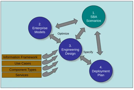
The reusable process for deploying SBA Scenarios into the GEOSS AIP Architecture is shown in Figure 2 and described in Table 1. This process is iterative with the main flow of activities as shown in the Figure, but the process is not accomplished in one pass.
Figure 2 – Design Process to Deploy SBA Scenarios
1 Cf., “Notes on the Synthesis of Form,” Christopher Alexander, Harvard Press, 1964, and “Systems Architecting,” Eberhardt Rechtin, Prentice Hall, 1991
2 International standards for architecture all require a set of views: IEEE 1220, ISO/IEC 10746, ISO/IEC 19793
4. Deployment Plan 1. SBA Scenarios 2. Enterprise Models 3. Engineering Design Component Types Information Framework Optimize Specify Use Cases Services
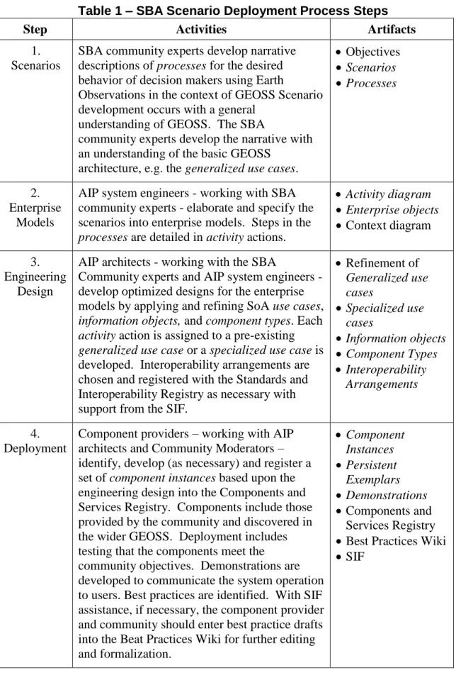
Table 1 – SBA Scenario Deployment Process Steps
Step Activities Artifacts
1. Scenarios
SBA community experts develop narrative descriptions of processes for the desired behavior of decision makers using Earth
Observations in the context of GEOSS Scenario development occurs with a general
understanding of GEOSS. The SBA
community experts develop the narrative with an understanding of the basic GEOSS
architecture, e.g. the generalized use cases.
Objectives Scenarios Processes 2. Enterprise Models
AIP system engineers - working with SBA community experts - elaborate and specify the scenarios into enterprise models. Steps in the
processes are detailed in activity actions.
Activity diagram Enterprise objects Context diagram 3. Engineering Design
AIP architects - working with the SBA
Community experts and AIP system engineers - develop optimized designs for the enterprise models by applying and refining SoA use cases,
information objects, and component types. Each
activity action is assigned to a pre-existing
generalized use case or a specialized use case is developed. Interoperability arrangements are chosen and registered with the Standards and Interoperability Registry as necessary with support from the SIF.
Refinement of Generalized use cases Specialized use cases Information objects Component Types Interoperability Arrangements 4. Deployment
Component providers – working with AIP architects and Community Moderators – identify, develop (as necessary) and register a set of component instances based upon the engineering design into the Components and Services Registry. Components include those provided by the community and discovered in the wider GEOSS. Deployment includes testing that the components meet the community objectives. Demonstrations are developed to communicate the system operation to users. Best practices are identified. With SIF assistance, if necessary, the component provider and community should enter best practice drafts into the Beat Practices Wiki for further editing and formalization. Component Instances Persistent Exemplars Demonstrations Components and Services Registry Best Practices Wiki SIF
6.1 Process Terminology
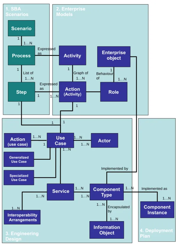
This section lists terminology used in the AIP Modeling process. The terms are taken from several standards. Some terms are unique to the AIP process. Figure 3 shows relationships between some of the terms. The following references are used in this section. The references are in order of precedence:
1. UML4ODP (ISO 19793) 2. RM-ODP (ISO 10746-2):
3. UML (OMG 07-02-05, UML 2.1.1))
Scenario (as used in AIP-2, scenario can be best understood considering the term Process from [UML4ODP])
The modelling of behaviour may be structured into one or more processes, each of which is a graph of steps taking place in a prescribed manner and which contributes to the fulfillment of an objective. In this approach, a step is an abstraction of an action in which
the enterpriseobjects that participate in that action may be unspecified. [UML4ODP])
Scenario defines the “business” objectives of the Community in using the GEOSS architecture.
A template for SBA Scenarios was developed early in AIP-2 process implicitly defining concepts. Refinement of the template based upon the preceding paragraph results in these concepts: A scenario may contain one or more processes. A process is defined in narrative form as a set of steps in a table.
Activity (Diagram):
An activity is a single-headed directed acyclic graph of actions, where occurrence of each
action in the graph is made possible by the occurrence of all immediately preceding
actions (i.e. by all adjacent actions which are closer to the head). [RM-ODP]
The notation for an activity is a combination of the notations of the nodes and edges it contains, plus a border and name displayed in the upper left corner. [UML]
Activity replaces ActivityGraph in UML 1.5. Activities are redesigned to use a Petri-like
semantics instead of state machines. [UML]
Enterprise object
Community object
Each enterprise object models some entity (abstract or concrete thing of interest) in the Universe of Discourse. A particular kind of enterprise object is a community object, which models, as a single object, an entity that is elsewhere in the model refined as a community. [UML4ODP]
Role: Identifies a specific behaviour of an enterprise object in a community. [UML4ODP]
Action: Something that happens [RM-ODP]
Use Cases:
Generalized Use Case Specialized Use Case
A use case is the specification of a set of actions performed by a system, which yields an
observable result that is typically, of value for one or more actors or other stakeholders of the system. [UML]
Each use case specifies a unit of useful functionality that the subject provides to its users (i.e., a specific way of interacting with the subject). [UML]
case specifies actions of value to GEOSS in general. A specialized use case refines a
generalized use case, as needed for a specific SBA community’s requirements.
Use cases for AIP focus on services and interoperability arrangements.
Actor
An actor specifies a role played by a user or any other system that interacts with the
subject. (The term “role” is used informally here and does not necessarily imply the technical definition of that term found elsewhere in this specification.) [UML]
Actors may represent roles played by human users, external hardware, or other subjects.
[UML]
Actors are external to the subject of the use case. [UML paraphrased]
Service:
A service is a distinct part of the functionality that is provided by an entity through
interfaces [ISO 19119:2005]
In AIP-2, services are types of computational objects as defined in [RM-ODP].
Interface
An interface is an abstraction of the behaviour of an object that consists of a subset of the
interactions of that object together with a set of constraints on when they can occur.
RM-ODP defines three types of interfaces: 1) A signal interface is an interface in which all the interactions are signals; 2) An operation interface is an interface in which all the interactions are operations; 3) A stream interface is an interface in which all the interactions are flows.
For SoA: an interface is a named set of operations that characterize the behaviour of an entity [ISO 19119]
In GEOSS, agreements about interfaces are termed interoperability arrangements.
Interoperability arrangements
GEOSS interoperability arrangements are to be based on the view of complex systems as assemblies of components that interoperate primarily by passing structured messages over network communication services. [GEOSS Strategic Guidance Document, October 2007]
By expressing interface interoperability specifications as standard service definitions, GEOSS system interfaces assure verifiable and scalable interoperability, whether among components within a complex system or among discrete systems. [GEOSS Strategic Guidance Document, October 2007]
Information object4
Information held by the ODP system about entities in the real world, including the ODP system itself, is modeled in an information specification in terms of information objects, and their relationships and behaviour. [UML4ODP]
Component type Component instance
A component represents a modular part of a system that encapsulates its contents and
whose manifestation is replaceable within its environment. [UML]
A component is modeled throughout the development life cycle and successively refined
into deployment and run-time. [UML]
For AIP, component types are design concepts that encapsulate information objects and provide services on the information through interfaces. Component instances are developments that have been deployed and are accessible at a network address.
Component instances are registered in the GEOSS CSR.
Figure 3 – Modeling Terminology 1 Optimize 1…N 1 1…N 1 1…N 1 Expressed as Expressed as Scenario Step Process Action (Activity)
Activity Enterpriseobject
Role 1. SBA
Scenarios 2. Enterprise Models
1 1…N List of Graph of 1…N Behaviour of Optimize 1 1…N Implemented as Use Case Actor 3. Engineering Design Service Interoperability Arrangements Information Object Component Type 1 Encapsulated by Action (use case) 1…N 1…N 1…N 1…N 1…N 1…N 1…N 1…N 1…N 1 1…N 1…N Implemented by Component Instance Generalized Use Case Specialized Use Case 4. Deployment Plan 1 1 1