Reprints available directly from the publisher Photocopyingpermittedbylicenseonly
under the Gordon and BreachScience Publishersimprint. Printed in India.
Self-Checking
Combinational Circuits with
Unidirectionally
Independent
Outputs
A. MOROSOW a’*, V. V. SAPOSHNIKOV
b,
VL. V.SAPOSHNIKOVbandM.GOESSELaDepartmentofComputerScience,Fault-TolerantGroupattheUniversityPotsdam,P.O. Box601553, Potsdam 14415,Germany;
Railway-TransportationUniversityofSt. Petersburg,
fir.
Moskovskij9,Sankt-Petersburg,RussiaInthispaperweproposeastructure dependentmethodfor the systematic design ofa self-checkingcircuit which iswelladaptedtothefault model of single gate faults andwhich
canbeused in testmode.
According to the fault model considered, maximal groups of independent and unidirectionally independent outputs ofanarbitrarily given combinational circuit are
determined. A parity bit is added to every group of independent outputs. A few
additionaloutputsareaddedtoevery group of unidirectionally independent outputs.In
theerrorfree case, these groupsof unidirectionalindependent outputs togetherwiththeir
correspondingadditionaloutputsareelements ofaunidirectional errordetecting code; forexample,aBergercodeor anr-out-of-s code.
Itisdemonstratedhowthepairsof (unidirectionally) independent outputs ofagiven
circuit can be determined. A simple heuristic solution for this problem based on a
modified circuitgraphisalso given.
The maximal classes of(unidirectionally) independent outputscan becomputed as
cliques ofadependencygraph where the nodes of the grapharetheoutputsofthecircuit.
The applicability of the proposed methodisdemonstrated for theMCNCbenchmarks
circuits.
Keywords." Self-Checkingcircuits,Independent and unidirectionally independent outputs,
Parity-code,Berger-code
1.
INTRODUCTION
The design of self-checking circuits[1-3] and
the combination of methods for on-line error
detection orconcurrentchecking and testing is of great interest now
(s.e.g.[4]).
It was first proposedin[5]that on-lineerrordetection byduplication and comparison be combined with testing to use the same hardware in different operational modes. These ideas were further developed in[6’7] for an
*Corresponding author.
333
arbitrary predictionfunction and for independent
outputsin
[8].
Parity predictionformutuallydisjointgroups of outputs of combinational circuits is a
special case ofthis approach
[9’1].
These methods,however, are generally not well-adapted to the
specific structure of the monitored circuit and the
technical faultmodel.
A
method for thedesign ofself-checking and self-testing circuits which is to
some extent adapted to the fault model of single gatefaults,isgivenin
[8].
In
thatpaper,independentoutputs ofthemonitored combinationalcircuitare the groups of outputs for which the parity is
computed, duplicated, inverted, and compared
with the parities ofthe originalcircuit.
In
normal operation mode,every single gate fault forcing anoutput to be erroneous for the first time will be detected.
As
well, every single gate fault will be detected intestmode.In
reality, however,there areonly very few cases where all the outputs of a
circuitcanbe combinedintogroups ofindependent outputs ofareasonablesizewhich are implemented
by completelydifferent gates.
In
[11],
weakly independent outputs are usedinstead of independent outputs for the design of
self-testing circuits.
Low
cost implementations ofself-testing circuits are very often possible,
but
inon-line mode faults may only be detected with
somedegree of latency andthe circuits arenot
self-checking.
As
a generalization of[8],
wepropose
in thispaper a structure dependent method for the
systematic design of self-checking combinational circuits which iswell-adaptedtothe faultmodelof single gate faults and the structure of the
con-sidered circuit.
Groups
ofindependent outputsaswell as groups of unidirectionally independent
outputs are determined.
Two
outputs are unidi-rectionally independent with respect to a given fault if, in the presence of this fault either bothoutputs arecorrect, onlyone outputis erroneous,
orboththe outputsareunidirectionally erroneous.
In
normaloperationmode,theproposedcircuitsare self-checking with respect to all single gate
faults.
In
test mode, these error detection circuits guaranteea 100% faultcoveragefor all nonredun-dantsinglestuck-at-0/1
faults.In
this paper, a given combinational circuit isconsidered.
In
[12]agiven circuit is modifiedbyuse ofaspecial input(output)encoding. Theproposedencoding technique guarantees that all internal
single stuck-at faults as well as all single stuck-at
faults of the input lines willresulteither insinglebit
errors or in unidirectional multibit errors of the outputs of the modified circuit. The rest of the paper is organizedasfollows.
In
section2,the basic notions and notations suchas unidirectionally independent outputs, maximal
groupsof tlnidirectionally outputs, and generalized
circuit graph are given. Basic theorems useful for the determination of independent outputs and unidirectionally independent outputs are also pre-sented.
In
section 3, it is shown how independent and unidirectionally independent outputs can beused to design self-checking circuits.
A
few addi-tional outputs are added to every group of unidirectionally independent outputs.In
the errorfree case, thesegroupsof unidirectionally
indepen-dent outputs are elements of an error detecting
codewhichdetects all unidirectionalerrors.
Every
group of independent outputs is checked by a
parity bit.
In
section4,it is explained how pairs of(unidirectionally) independentoutputs canactually
be determined. The determination of maximal
groups of (unidirectionally) independent outputs
can be reduced to the standard graph-theoretical
problemofthedeterminationofmaximal cliques of
adependency graph,wherethe nodesofthegraph
are theoutputs of thecircuit considered.
In
section 5 experimentalresultsforbenchmark circuitsare given.2. BASIC
NOTIONS AND NOTATIONS
In
thispaperweconsideracombinational circuitfc
with n binary inputsx,...,Xn and m binary
out-pUtsyl
f(xl,..., Xn),...,
Ymfm(Xl,..., Xn),where
fl,...,fro are n-ary Boolean functions.
Let
x=(x
l,...,Xn),
andy (y,...,Ym).
The setof technical faults consideredisdenoted
by
b=
{b0,
b,...,bK},
whereb0
denotes theab-senceofafault.
TheoutputYiunder input x in the presenceofa
fault
bj
Eb
is describedbyYi,j
fi
(bj,
x).
Then,for thecorrectoutput in the absence ofa
fault, wehave
The notionofunidirectionally independent
out-putsis introduced inthe following definition.
DEFINITION The outputs Yi and Yk are called
unidirectionally independent with respect to the fault
Cj
E andwith respect to a subsetX
c_
X
of the inputsetX
ifwehave, for xEX,
either1. fi(x)
fi(j, x)
andf(x)
f(j, x)
or
2.
(fi(x)--fi(bj, x)
andfk(X) fk(bj, X))
or (fi(x)-7/=fi(j, x)
andfk(X)
fk(j, X))
or3.
fi(x)#fi(j,x)
andfk(x)fk(j,x)
and fi(x)=fk(X).
According to this definition, two outputs are unidirectionally independent if they are both correct, ifonlyoneof them iserroneous,orifthey
are both unidirectionally erroneous.
In
the lastcase,bothoutputsarechanging from0to orfrom
toO.
Independent outputs are a special case of
unidirectionally independent outputs.
Outputs
areindependent if only the conditions and 2 of
Definition are fulfilled. Thus two outputs are
independent ifthey are either both correct or if
onlyoneof them is erroneousat atime.
In
thefollowingwesometimesomitthe subsetX,
especially if this subset is not specified.
Now
wegeneralize the definition ofa pair of
unidirection-ally independent outputs with respect to a set of
faults andaset of outputs.
DEFINITION 2 The outputs Yi and Yk are called
unidirectionally independent withrespecttoaset
of faults if these outputs are unidirectionally independent with respecttoeveryfault
Cj
.
DEFINITION 3 The outputs Yi,’’’,Yir form a
group of unidirectionally independent outputs if
every pair of these outputs is unidirectionally
independent.
Similar definitions can be given for independent outputs.Independent outputscanbe determinedby
useof the generalized circuitgraphintroduced in
[9].
In
a similar way, unidirectionally independent outputs can be determined by a modification ofthis generalized circuit graph. This will be
explained now.
A
combinational circuit C can be described bythe connections between outputs and inputs of its
logical gates. The gates and the direct outputs of
the circuit are called "elements" of the circuit. These elements can be combined into maximal
classes
Ci
of elements with one output. Themaximal classes
Ci
are identified with the nodesNi
of the generalized circuitgraph G.A
nodeN1
ofthis graph G is connected with a node
N2
by andirectededgedirectedfrom
N1
toN2
ifthe outputofthe class
C1
isconnectedto one of the inputs of the gates of the classC2.
The maximal classes of elements with one output corresponding to the nodes of the generalized circuit graph can be determinedasfollows"1. Create a subset for each non-fanout output of
thecircuit, and markeachelement.
2. If theoutputofan element isconnected onlyto
marked elements of a single, already existing
subset, addtheelementtothe subset andmark
the
element.
3. Ifthe outputofanelementisconnectedonlyto
already marked elements not all belonging to
thesamesubset markthiselement andcreate a
newsubset containingthiselement. The element
isthe outputof thenewlyopenedsubset.
4. Continue until all elements are marked and
belongto asubset.
In
thenextstep thecircuitgraph G(N, V)
willbe modified into the modified circuit graph
G
=(N’, V’).
In
addition to the nodes N of thecircuit graph
G,
a node nl,...,nm is assigned toeveryoutputYl,...,Ymof the circuit
ft.
Forthe setN’
of nodesofG’,
wehaveN’=
N
tA{nl,...,
nm}.
In
the modified circuitgraph Gt,
the nodes Ni,Nk
EN
areconnected byanon-marked edgeif there isapathfrom the output element of the node
Ni
to oneof the inputs of the output element of
Nk
.with
aneven number of inversions. The nodes Ni,
Nk
ENareconnected by amarked edge ifthereis a path
from theoutputelement ofthe node
Ni
tooneof the inputs of the output element ofNk
with an oddnumber of inversions. Inversion of the output of theoutput element of
Ni
aswellasinversionsatthe input of the output element ofNk
are taken into account. Inversions at an input of the output element ofNi
aswellasinversions of theoutput ofthe output element of
Nk
are not considered forthe marking of the edge from
Ni
toNk.
Thus,twonodes of the modifiedgraph
G’
areconnectedby at most two edges, a marked one and an
unmarkedone.
As
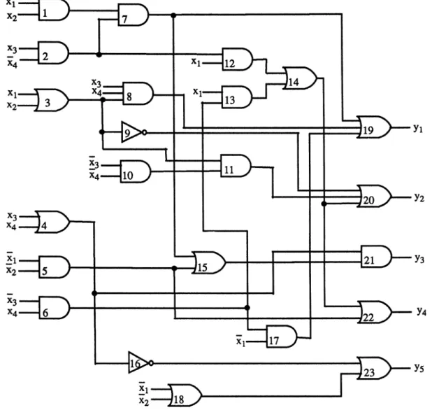
an example we consider the combinationalcircuit of Fig. 1, which implements the following
Xl X2
fiveBoolean functions:
Yl
("nXl)X2X3(x4)V
(x
VX2)X3X4
k/(X1)
(-’nX3)X4
Y2-(Xl
Vx2)
VXlX3(-’nx4)
k/Xl(x3)x4
V(Xl
Vx2)(-nx3)(-x4)
Y3(x3
Vx4)((’Xl)(x2)V (Xl)X3(-x4))
Y4(Xl)(x2) k/Xl(X3)X4
VXlX3(’-nx4)
Y5-(x3
Vx4)
V(-xl)
V(-x2).
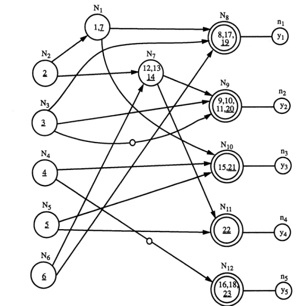
The modifiedgeneralizedcircuitgraphis shown in Fig. 2. AccordingtoFig.2,twoedgesaredrawn
Yl
Y2
Y3
23-)
y5N1
N$
nl
N2
N7
N9
n2
N10
n3
N5
Nil
N6
N12
n5
FIGURE2 Modified generalizedcircuitgraph of the examplecircuitof Fig.1.
fromthenode
N3
to the nodeN9.
The first edgecorresponds toa pathwith one inversion
(an
oddnumber ofinversions)fromelement3toelement 20 viaelement 9. The secondedgeviaelement 11 has
noinversion
(an
evennumberof inverversions).Similarly, as in
[9],
anodeNi
of the modifiedgen-eralized circuit graph is called structural essential for the node
Nk
if thereis atleast onepathfromNi
to
Nk.
If thereis nopath fromNi
toNk
the nodeNi
iscalled structural non-essential for the node
Nk.
The output of the output element ej of the
maximal class
C
corresponding to the nodeN
willbe denotedbyzj.Theupperindex rof
e
isthenumber of the element in the circuit
fc
if the elementsofthe circuit are numbered.We
are mainly interested in outputs which are(unidirectionally) independent with respect to
functionalfaultsof single gates (single gate
faults).
The maximal classes of elements with one output
DEFINITION 4 The outputs Yi and Yk are called
(unidirectionally) independent with respect to the node
Nj
if these outputs are (unidirectionally)independent with respect to all single gate faults withinthe maximal class
Cj.
PROPOSITION The outputs Yi and Yk are
unidi-rectionally independent withrespecttothe node
N
of the generalized circuitgraphif andonlyifwehavedyi dyk
(Yi
Yk)
0.Fi,k;j
jj"
dzj
(1)
Therebyzjis theoutputof theoutputelement
e
ofthe maximal class
C
correspondingtothe nodeNj.Proof
A
faultwithintheclassCj
whichforcesanoutputYi tobe erroneousforsomex EX necessarily
changesthe output
zj(x)
ofCj
intozj(x),
andforevery input xEX there exists a single gate fault
within
Cj
which forceszj(x)
to be-zj(x). (For
z(x)
(0),
astuck-at-0(1)
fault oftheoutputgate ofC
results inan outputof 0(1)).
The inputs of
fc
for which achangeof theoutputzjof
Cj
resultsinachangeof the outputYs,s i,k,are determined by
dys/dzj(x)=l.
Thusdyi/
dzj(x).dyk/dZj(X)=
determines the inputs forwhichachange
ofzj
results inasimultaneouschangeof both the outputs Yi andYk, respectively,yi(x)
yk(X)--- determines the inputs forwhich we have
yi(x)=-yk(x), and
dyi/dzj(x).dyk/dzj(x)(yi(x)
@
yk(x))-
determines the inputs for which achange of zj simultaneously changes the outputs
yi(x) andyk(x) in different directions. From these equationswe conclude
(1).
For independent
outputs,
wehave thefollowingproposition.
PROPOSITION The outputs Yi,and Yk are
inde-pendentwithrespecttothe node
Nj
of thegeneral-izedcircuitgraphif andonlyifwehave
dyi.
dyk
0.(1’)
F’
i,k;jdzj
dzj
For
practical applications, the following sufficient conditions for the determination of(unidi-rectionally)independentoutputs with respect to a
node
N
of the modified generalized circuit graphareofinterest.
CONDITION2 The outputsYiandYkare
unidirec-tionallyindependentwith respecttothe node
Nj
if 1.N
isstructural non-essential foratleast oneofthe outputnodesniornk,
or
2. all thepath’sfrom
Ni
toniand fromN
to nginthe modifiedgeneralized Graph
G’
containeitheran evennumberof markededgesor anodd number
ofmarkededges.
CONDITION2 The outputsYiand ygare
indepen-dent withrespectto the node
N
ifNj
isstructural non-essential foratleastone of theoutputnodesniand
n.
Example
By
use of Condition 2, the outputs Yand
YE
can be dependentwith respect to thenodeN3, and the outputs y3 and Y5 can be dependent
withrespectto the node
N4.
To
decide whetherornot they are unidirectionally independent, we
compute dye dyl x3x4
(-nx1)x
V(x1)x4
Vx3x4,dz3
33
dy__3
dy5(’Xl)(’nX2)
V(-nXl)X3(-x4),
4
XlX2.dz4
Nowwecheck condition 1:
dyl
dye2
(Yl
Y2)
x3x4 0dz3
dz3
dY--23" dY---25
(Y3
@Ys)
0.dz4
dz4
Thus the outputs ya and Y5 areunidirectionally
independent andthe outputs Y andY2 are not.
The following theorem is of great practical interest for the determination ofunidirectionally
independent outputs.
PROPOSITION3
Two
outputs Yi and Yk are(uni-directionally) independent with respecttothesetof all single gate faults iftheyare(unidirectionally) independent with respect to all nodes Nj of the generalizedcircuit graph.
3. DESIGN OF SELF-CHECKING
CIRCUITS
WITH
UNIDIRECTIONALLYINDEPENDENT OUTPUTS
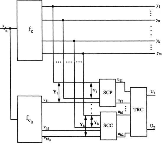
Figure 3 shows the general structure of the
pro-posed self-checkingcircuit.
The outputs Yl,...,’Ym of the circuit
f
arearranged in h different groups Y1,...,Yh with
Yi
{Yi,..., Yini},
1,...,h, of independentoutputs and unidirectionally independentoutputs.
Every
groupYi
{Yil,...,
Yini},
i= 1,...,h,willbesupplemented with some additional outputs
vil,...,vit forming an extended group
Yi
{Yi,-..,
Yini, Vh,...,Vhti}.
Iftheoutputs ofagroup
Yj
areindependent onlya single parity bit vj is added.
In
Fig. 3Y
isassumed to be a group of independent outputs.
Therefore only a single parity bitis addedto this
group.
Iftheoutputs ofagroup
Yi
are unidirectionallyindependent the ti additional outputs are deter-mined in such a way thatthe outputsYi,... ,’Yini,
Vh,...,Vhti areelementsof
an
error detecting codeforall unidirectional errors.
In
Fig. 3 thegroupYh
issupposedtobea group of unidirectionally independent outputs. Thus the outputs Vh,...,Vhti are added.A
possible error detecting code is aBerger-code[3] or an s-out-of-r code[141 where s is the
numberof l’s andr isthe number of bits,r ni
+
ti.To
determinetheelements of ans-out-of-rcodewe.consider all the possible binary ni-tupels of the
outputsYil,...,Yin of the group
Yi
for xEX.Let
Mi
(mi)be the maximal(minimal)
numberof l’s ofthisn-tupels.Thentiis determinedbyti
Mi
mi.Itiseasy todetermine the outputs Vhl Vhti such
that Yi Yi.i,Vh Vhtiareelementsofan
Mi-out-of-(ni
+
ti) code.If the number of l’s ofthe considered ni-tuple
Yil,...,Yiniis Ki,mi
_< Ki
_<
Mi, thenexactlyMi
Ki
additional outputs Vhl,...,Vhti have to be 1. TheseMi
Ki
ones canbe arbitrarily distributedovertheadditional outputsVhl,...,Vhti.
These additional outputs will be jointly
imple-mented by use of an additional combinational circuit
fca
as shown in Fig. 3.Every
fault in theadditionalcircuit
fea
willbe detected.Every
extended groupYi
ischecked byuseofaself-checking code-checker[2’3’15’16] with two
out-puts ui,ui2 with ui =-ui2 in the fault free case. These outputs arecompacted byatwo-rail checker
TRCwith2h inputs and2 outputs
U1
andU2,withU1
U2
in the fault freecase.Every
single gatefaultof the circuit
f
andeveryfault ofthecircuitfe
will bedetectedbyanoutputui ui2for some ifitforcesatleast oneof theoutputs of
fc
orfa
tobeerroneousfor the first time. Sinceui ui: implies
U
U2
atthe outputofthetwo-railchecker, everysingle gate fault of
f
andfca
will be immediatelydetected.
In
Fig. 3 the groupY
ischeckedbyaself-checkingparity checker
SCP,
and thegroupYh
ischecked by a self-checking,code checker
SCC
forthe correspondingcode.
4.
DETERMINATION OF INDEPENDENT
AND
UNIDIRECTIONALLYINDEPENDENT OUTPUTS
If
Ri,
j--
the outputs yi and yj are obviouslyindependent, if
Ri,j
0
wehavetocompute the expressionFti,j;k
accordingto(1’).
Iffor all k withNk
ERi,
j,Ri,
0
we haveFi,,j;k
0, theoutputsYi andyjare independent.
For
the determination of pairs ofunidirection-ally independent outputs thisprocedurehas tobe
modified.
1’.
To
every node nj, j 1,...,m, we assign twosets Tj and
Tj
A
node Nk,Nk
N,
belongsto
Tj
(T[)
if there exist apath fromNk
tonjwith an even
(odd)
numberofinversions.2’.
For
every pair of nodes ni,nj with C-j,i,j 1,...,n, we determine the set
Mi,j--Ti
71(Tj’)
UTj
71(Ti).IfMi,
=0,
theoutputsYiandyj are obviously unidirectionally independent
andtheoutputsYiandyj are calledgraphically
unidirectionally independent. If
Mi,j
0
wehavetocomputethe expression
Fi,
j; kaccordingto(i).
If for all k with
NkGMi,j,
Mi,j
we haveFi,j;k
=0, the outputsYiandyjare unidirectionallyindependent.
For
the circuitfe
of Fig. with the generalizedcircuit graph’of Fig. 2,wehave
S1
--{N1,
N2, N3, N6,N8),
S2
{N2,
N3, N6, N7,N9
},
$3
={Ni,
N2, N4,Ns,
NlO},
$4
--(N2,
Ns,
N6, N7,Nil
},
$5
--{N4,
N12}
fromwhichweconcludethat
Pairs ofindependentoutputs can be determined in the following steps:
1. Consider the nodes n,...,nm of
f.
To
everynodenj,j 1,...,m,weassignaset
Sj.
Therebya node Nk,
Nk
EN
belongs toS
if thereexistsapathfrom
Nk
ton.
2. For every pair of nodes ni,nj with
i:/:
j,i, j 1,..., n, wedetermine the set
Ri,
Sif)Sj.
R1,5
S1
f’]$50,
R2,5
$2f-’l$50,
R4,5
$4I")$50,
andthe pairs ofoutputsYl andYs,Y2 and Y5 and Y4 andY5 aregraphicallyindependent.
are
T1
--{N1,N2,
N3,N6,N8},T’
(,
T2
:{N2,
N3, N6,N7,N9},
T
{N3 }
T3 ={N,
N2, N4,Ns,
NlO},
T
T4
--{N2,
Ns,
N6,N7,Nil
},
T
Ts
={N2},
T’
{N4}.
For we haveMi,j,i
-
j,i,j 1,...,5M12
{N3},M13
},
M14
O,M5
},
M23
},
M24
},
M25
},
M34
},
M35
{N4},
M45
}andthepairs of output nodes
(nl,
n3),
(nl,
n4), (nl, ns), (n2, n3), (n2, n4),
(n2,
ns),
(n3,
n4)
and(n4,
ns)
are graphically unidirectionally independent.
If we would like to determine not only the
graphically unidirectionally independent pairs of
outputs, the cases
Mi,
y
(,
i.e.M1,2
{N3}
andM3,5--
{N4}
havetobeconsidered in more detail.Since wehave dy dy2
F1,2;3
3
(x)
"z3
(x)(yl (x)
@y2(x))
X3X4 0 and dy3 dy5F3,5;4
z4
(x)"
z4
(x)(y3(x)
q)ys(x))
0,the outputsY3and Ysareunidirectionally indepen-dent and the outputs Y and Y2 are not unidi-rectionallyindependent.
Now
wedescribe how(maximal)
setsofindepen-dent outputs can be determined.
To
this end wedraw a firstdependency graph
G=
(N
1,
gl).
The nodes N ofG are the outputs y,...,Yn of theconsidered circuit
fe.
Two
nodesYi,Y
N arecon-nected by an edge ifthe pair of nodes is
(graphi-cally) independent.
Every
group of independentoutputscorrespondstoacompletesubgraphofG
1,
i.e. aclique ofG
1.
The determination of a completesubgraphis astandardproblemofgraph theory.
In
a similar way, we determine sets of unidi-rectionally independent outputs.We
drawaseconddependency graph G2
N
2 N2Q..N_
V2)
Thenodes ofG
2are againthe outputs Y1,. Ynof the considered
circuit
fe.
Two
nodesYi,YjEN2areconnectedbyanedgeifthese nodes are (graphically)
unidirection-ally independent.
Every
group of unidirectionallyindependent outputs corresponds to a complete subgraph
of__G
2,
i.e.acliqueof__G
2.
In
thefollowingexample we restrict ourself to the graphically
independentand graphicallyunidirectionally
inde-pendentoutputs.
The graph G of graphically independent pairs
ofoutputsof
fe
isgivenin Fig. 4. The threepossiblemaximal complete subgraphs consist of the nodes
nl and ns, n2and n5 andn4 and
ns.
Fig. 5 showsthe graph G2 of the graphically unidirectionally
FIGURE4 Graphof independent outputs.
Yl
Y2
Y3
Y4
Y5
SCC1
Ull
U12
TRC
U1
U2
v21
v2
2
Vl
1
SCP
u22
FIGURE6 Self-checkingcircuitof theexampleof Fig. 1.
independent outputs of
ft.
The maximalcom-plete subgraphs ofG2 consist ofthe sets ofnodes
{nl,
n4,ns}, {nl,
n3,n4}, {n2,
n3,n4}, {n3,
n4,ns}
and{n2,
n4,ns}.
We choose the set
Y1
{n2,ns}
of graphicallyindependent outputsandthe set
Y2
{nl,
n3,n4}
ofgraphically unidirectionally independent outputs.
Totheset
Y1
{Y2,
Ys}
ofgraphicallyindependentoutputs a single parity bit vl,v
=--(Y2
(R)Ys)
isadded. Thuswe have
Y1
{Y2,
Ys,Vl}.
To the outputs Yl, Y3, Y4 ofthe group
Y2
twoadditional outputs v21,v22 are added to form a
Beger
code with three information bits and twocontrol bits. All the additional outputs vl,v2 and
v22canbe jointly implemented. TheoutputsY2, Ys,
and Vl of the group
Y1
are checked by a self-checking parity checker SCP. The groupY2
ischecked by a self-checking
Berger
code checkerSCC
1. The outputs of the SCC and the SCParecompacted by a self-checking two-rail-checker
TRC
asshowninFig. 6.The resulting circuit is self-checking.
5.
EXPERIMENTAL RESULTS
Table showes the experimental results for the
MCNC
benchmarks.Thefollowing abbreviationsareused:
inp: number of inputs
out: number ofoutputs
pgio: numberofpairs of graphically independent outputs
pguo: number of pairs of graphically
unidirection-allyindependent outputs
circuit inp out pgio
TABLE Experimental results
pguo pio puo go bB bP bT ao
2 3 4 cm138a 6 8 cu 14 11 33 cm162a 14 5 decod 5 16 27 ldd 9 19 29 apex7 49 37 361 z4ml 7 4 x2 10 7 3 c8 28 18 96 f51m 8 8 ttt2 24 21 105 vda 17 39 11 pml 16 13 63 5 6 7 8 28 28 54 33 54 2 3 4 4 120 27 120 79 61 171 522 379 555 12 3 6 3 14 4 15 4 152 96 152 2 5 7 4 116 128 148 7 17 169 343 14 68 69 74 2
puo: number of pairs of unidirectionally
inde-pendentoutputs
go: number of groups of independent and unidirectionally independentoutputs
bB:
number
of additional bits forBerger
CodesbP: number of additional paritybits
bT: total number of additional bits
(bT=
bB
+
bP)
ao: additional
area
overhead in percent ofthearea of the original circuit
The pairs of graphically independent outputs
pgio
(column
4)
and the pairs of graphically unidirectionally independent outputs pguo (col-umn5)
are determined by use of the modifiedgeneralizedcircuit
graph.
The pairs of independentoutputs pio
(column 6)
and the pairs ofunidi-rectionally independent outputs puo
(column 7)
are determined according to
(1)
and(1’)
respec-tivelywhere thecorrespondingBoolean derivations
havetobe takenintoaccount.
The Boolean derivations in
(1)
and(1’)
arecomputed by use of the program system MIS
[17].
The corresponding Boolean functions are
repre-sented as
BDD’s.
Graphically(ufiidirectionally)
independent outputs are always (unidirectionally) independent. Therefore, the number of pairs of (unidirectionally) independent outputs is always greater than or equal to the number of pairs of graphically (unidirectionally) independent outputs.
9 10 11 12 4 4 15 5 5 75 5 5 107 5 5 <1 5 5 31 3 10 13 119 3 3 62 2 3 5 85 6 6 156 6 7 55 4 5 9 79 26 26 60 3 4 88
The minimalnumberofmutuallydisjointgroups
of independent and unidirectionally independent
outputsgo are given in column 8.
Groups
of unidirectionally independent outputsare monitored by
Berger
Codes. The number ofnecessary additional bits bB is represented in
column 9.
Groups
of independent outputs arechecked by additional parity bits. Thenumber of additional parity bitsbPisgivenin column 10. The totalnumber ofcheck bitsbT (Bergercode bits and parity bits) is given in column 11 ofTable
I.
Theareaoverhead of the additional circuit
fc
isshownintherow12of Table. Theadditional circuit
fca
wassythesized byuseofthestructurally givencircuit
fc
in the following way: If the outputs ofa groupYi-- {Yi,..., Yihi}
are independent a singleaddi-tional output vi ofthe paritybitis determinedby
connecting the outputs Yil,...,Yihi by
XOR-gates.
If the outputs of a group Yj
{yj,...,yjj}
areunidirectionally independent the outputs
{yj,...,
yjj}
are connected to a counter of zerosto determine the additional bits ofa
Berger
code. Then all the outputs of the circuitfea
are jointlyoptimized by use of the standard MIS-algorithm
script.rugget.
The necessary computing time ona
SUN
Work-station Spark 10 including the determination of pairs of independent and unidirectionally indepen-dent outputs, the determination of maximal
circuit wasin therange of 0.33to3376.46seconds. The average additional area overhead is 71%.
6.
CONCLUSIONS
In
thispaperanewstructuredependentmethod forthe design ofself-checkingand self-testing combi-nationalcircuitswasproposed. Maximalgroupsof independentoutputsandunidirectionally indepen-dent outputs are determined.Itisshownhow pairs of (unidirectionally) independent outputs can
heuristically be determined by a simple
graph-theoretical algorithm. Maximal groups of
(unidi-rectionally) independentoutputscan becomputed
as cliques of a dependency graph, which is a
standard graph-theoretical problem.
A
singleparity bit is added toevery group ofindependent
outputs.
A
few additional outputs are added toevery group of unidirectionally independent out-puts in such a way that these groups of
unidi-rectionally independent outputs and the
corresponding additional outputs are elements of
aunidirectional errordetecting code. This method is explained in detail for a simple example. The
applicability of the proposed method is
demon-strated for the
MCNC
benchmarks.Acknowledgment
The authors are very grateful to the reviewers of
thispaperfor theirhelpfulcomments.
References
[1] P. K. Lala, Fault Tolerant and Fault Testable Hardware
Design.PrenticeHall, Englewood-Cliffs,N.J.
[2] V. V.Sapozhnikov and V1.V.Sapozhnikov, Self-Checking
Checkers for Balanced Codes. Automation and Remote
Controlvol. 53,No3, part 1,321-348(1992).
[3] V. V.Saposhnikov and V1.V. Saposhnikov, Self-Checking
DiscreteCircuits(in russ.)Energoatomisdat,St.Petersburg (1992).
[4] S. K. GuptaandD. K.Pradhan,Can ConcuentCheckers
HelpBIST?, Proc.1992Intern.Test Conference,pp.140-150
(1992).
[5] R. M.Sedmak, Design for Self-Verification.AnApproach
for Dealing with Testability Problems in VLSI-based
Design. Proc. 1979 IEEE Test Conference, pp. 112-120
(1979).
[6] E. Fujiwara,N. Mutoand K. Matsuoka,ASelf-Testing
GroupParityPredictionChecker anditsUsefor
Built-in-Testing. IEEE Trans. Comp., vol. C-33, No 6, 578-583
(1984).
[7] T. R. N. RaoandE.Fujiwara,ErrorControl Coding for
Computer Systems,PrenticeHall(1989).
[8] E. S. Sogomonyan, Reliability of Self-Testing using
Functional Diagnosic Tools. Automation and Remote
Control, vol. 49,No 10,Part2, October 1988, pp.
1376-1380.
[9] E. S. Sogomonyan, Design of Built-In Self-Checking
MonitoringCircuitsforCombinational Devices.
Automa-tionandRemote Control, vol. 35,No 2, part 2, 280-289
(1974).
[10] E. Fujiwara, A Self-Testing Group Parity Prediction
Checker and its Use for Built-in Testing. Proc. 13th
Symposium Fault-Tolerant Computing, Milano, pp.
146-153(1983).
[11] E. S. SogomonyanandM.Goessel, Design of Self-Testing
andOn-lineFaultDetectionCombinational Circuits with
WeaklyIndependentOutputs. JETTA,4,267-281(1993).
[12] F.Y.BusabaandP. K.Lala, Self-CheckingCombinational
Circuit Design for Single and Unidirectional Multibit
Errors, JETTA, 5, 19-28(1994).
[13] J. M. Berger, A Note on Error Detecting Codes for
Asymmetric Channels.InformationandControl4, 68-73
(1991).
[14] D. A. Anderson and G. Metze, Design of Totally
Self-Checking Check Circuits for m-out-of-n Codes. IEEE
Trans. Comp.,vol.C-22,263-269(1973).
[15] M. A. Marouf and A. D. Friedman, Design of
Self-Checking Checkers for Berger-Codes. Proc. Int. Symp.
Fault-Tolerant Computing, 179-184(1978).
[16] S. Kundu and S. M. Reddy, Embedded Totally
Self-Checking Checkers.APracticalDesign.IEEEDesignand
TestofComputers,August1990,5-16.
[17] R. K.Brayton,R. Rudell, A.Sangiovanni-Vincentelli and
A. R. Wang, "MIS: Amulti-level logic optimization
prog-ram," IEEE Trans.Computer-AidedDesign,7,1062-1081.
Authors’ Biographies
Andrej
Morosow
received the M.S. degree in electricalenigneeringfrom the University of Rail-way Engineering, St. Petersburg, Russia, in 1992.From
1992 to 1996 he was with Max-Planck-Society Fault Tolerant ComputingGroup
at the UniversityPotsdam,Germany.
Nowheis withtheComputer
ScienceDepartment
of the University ofPotsdam,
Germany,
where he is working towardhis Ph.D. degree. His research interest are the
design of self-checking and self-testing circuits. Prof. Valerij Saposhnikov received the M.S.
degree
(1963),
the Ph.D. degree(1968)
and thedoctoral degree
(1982)
all in electrical engineering from the University of Railway Engineering,St. Petersburg (formerly Leningrad), Russia.
In
1982 he became a professor, and in 1989 a vice president of this university. He published as an
author and coauthor about 250 scientific papers and 8 books in russian language in the field of synthesis, diagnosis, self-checking circuits and control systems for railway transportation. Since
1992 he is avisiting professor of the Max-Planck Fault TolerantComputing
Group
atthe Universityof Potsdam,
Germany.
He is a member of theRussian Transportation Academy and of the InternationalAcademyof Higher Education.
Prof. Vladimir Saposhnikov received his M.S.
degree
(1963),
the Ph.D. degree(1969)
and thedoctoraldegree
(1984)
all in electrical engineeringfrom the University of Railway Engineering St.
Petersburg (formerly Leningrad), Russia. Since
1987 he is aprofessor and since 1991 the head of
adepartment. Since 1992 heis avisitingprofessor
of the Max-Planck Fault Tolerant Computing
Group
at the University of Potsdam,Germany.
He
is the author and coauthor of about 300 scientific publications and 8 books in Russianlanguage. His research interests are synthesis and
diagnosis of discrete systems, self-checkingsystems
and fail-safe transportation systems. He is a
member of the Russian Transportation Academy
and of the International Academy of Higher Education.
Prof. Michael Goessel received theM.S.
Degree
(1965)
and the Ph.D.Degree (1968),
both inphysics, from the University of
Jena, Germany
and the doctoral degree in
Computer
Science(1971)
from the Technical University ofDresden,Germany.
From 1966 to 1968 he was a researchassistent at the University of Leningrad.
From
1969 to 1991 he was with the Central Institute of Cybernetics
(ZKI)
of the Academy of Sciences, Berlin, of the formerly GDR.In
1992 he wasappointed as the head of the Fault Tolerant Computing
Group
of the Max-Planck-Society atthe University of Potsdam,
Germany.
Since 1994 he is a full-timeprofessor ofComputer
Science atthe University of Potsdam,
Germany. He
is theauthor andcoauthor of7 books,including "Error
DetectionCircuits",
(Goessel,
Graf, McGraw-Hill1993)
and"Memory
Architecture and ParallelInternational Journal of
Aerospace
Engineering
Hindawi Publishing Corporation
http://www.hindawi.com Volume 2010
Robotics
Journal of Hindawi Publishing Corporationhttp://www.hindawi.com Volume 2014
Hindawi Publishing Corporation
http://www.hindawi.com Volume 2014
Active and Passive Electronic Components
Control Science and Engineering
Journal of
Hindawi Publishing Corporation
http://www.hindawi.com Volume 2014
Machinery
Hindawi Publishing Corporation
http://www.hindawi.com Volume 2014
Hindawi Publishing Corporation http://www.hindawi.com
Journal of
Engineering
Volume 2014
Submit your manuscripts at
http://www.hindawi.com
VLSI Design
Hindawi Publishing Corporation
http://www.hindawi.com Volume 2014
Hindawi Publishing Corporation
http://www.hindawi.com Volume 2014
Shock and Vibration
Hindawi Publishing Corporation
http://www.hindawi.com Volume 2014 Civil EngineeringAdvances in
Acoustics and VibrationAdvances in
Hindawi Publishing Corporation
http://www.hindawi.com Volume 2014 Hindawi Publishing Corporation
http://www.hindawi.com Volume 2014
Electrical and Computer Engineering
Journal of
Advances in OptoElectronics
Hindawi Publishing Corporation
http://www.hindawi.com Volume 2014
The Scientific World Journal
Hindawi Publishing Corporation
http://www.hindawi.com Volume 2014
Sensors
Journal ofHindawi Publishing Corporation
http://www.hindawi.com Volume 2014
Modelling & Simulation in Engineering Hindawi Publishing Corporation
http://www.hindawi.com Volume 2014
Hindawi Publishing Corporation
http://www.hindawi.com Volume 2014
Chemical Engineering
International Journal of Antennas and
Propagation
International Journal of
Hindawi Publishing Corporation
http://www.hindawi.com Volume 2014
Hindawi Publishing Corporation
http://www.hindawi.com Volume 2014
Navigation and Observation
International Journal of
Hindawi Publishing Corporation
http://www.hindawi.com Volume 2014
Distributed Sensor Networks International Journal of