Sharif University of Technology
Scientia IranicaTransactions B: Mechanical Engineering www.scientiairanica.com
Rolling-schedule multi-objective optimization based on
inuence function for thin-gauge steel strip in tandem
cold rolling
H.N. Bu
, Z.W. Yan, D.H. Zhang and S.Z. Chen
State Key Laboratory of Rolling and Automation, Northeastern University, Shenyang 110819, Liaoning, China. Received 16 June 2015; received in revised form 3 September 2015; accepted 8 December 2015
KEYWORDS Tandem cold mill; Rolling schedule; Mathematical model; Multi-objective optimization; Inuence function.
Abstract. The setting of rolling schedule in tandem cold mill is one of the most crucial contents in rolling process, which will have a direct impact on product quality and production eciency. According to the actual requirements in the rolling process, a multi-objective function based on inuence function method was built. The multi-objective function was aimed specially at thin gauge strip and solved by Tabu search algorithm. Meanwhile, in order to avoid strip slipping by the reduction of friction coecient, the tension schedule was corrected according to the rolling length of work roll. The proposed optimization method was successfully applied to a 1450-mm 5-stand tandem cold mill. Application results show that the optimized rolling schedules are more close to the actual requirements and the atness quality is improved greatly.
© 2016 Sharif University of Technology. All rights reserved.
1. Introduction
In the tandem cold rolling process control system, development of rolling schedule is the most funda-mental work and the core of the production pro-cess. Reasonable design of the rolling schedule has a deep impact on the yield and quality of nished steel. In recent years, many researchers have proposed dierent rolling schedule optimization algorithms for tandem cold rolling [1-5]. Zhao et al. took equipower margin and overcoming scratch as objective functions to establish rolling-schedule multi-objective optimized model and optimized it with adaptive chaoticmutation shued frog leaping algorithms.
Yang et al. adopted a genetic algorithm to opti-mize rolling schedule by the targets of load equalization and ne shape [6]. Wei et al. put forward a rolling-force revised model and designed an improved
adap-*. Corresponding author.
E-mail address: bhn [email protected] (H.N. Bu)
tive genetic algorithm for rolling-schedule optimization calculation. Che et al. adopted equal relative load as objective function, used SUMT algorithm to change constraints to non-binding conditions, and applied a PSO algorithm to optimize objective functions. Mehrdad Poursina et al. used a genetic algorithm to optimize the process from the power consumption and damage evolution points of view [7]. Yang et al. used BP neural network to predict rolling force and multi-objective fuzzy method to optimize objective functions [8].
In the past decade, with the rapid development of rolling technology and modern rolling-mill design theory, people applied optimization techniques to the rolling elds gradually and rolling schedule optimiza-tion design has made considerable progress. The products with higher dimensional accuracy and better mechanical property have been produced. Among them, cold rolled sheet has been applied to electronics, automobile, light industry, textile, and other sectors widely due to its characteristics like good atness,
bright surface, and uniform performance [9-14]. How-ever, with the explosive development of modern indus-trial technology and automated production processes, sectors of the national economy feel the increasingly widespread need for rolled products with higher pre-cision of dimensions. Thus, in this article, rolling schedule optimization algorithm is proposed for thin gauge strip to obtain products of better atness and performance.
2. Online calculation models for control parameters
2.1. Deformation resistance model
Deformation resistance reects the eects of accumu-lated work hardening in tandem cold rolling and is the most basic technological parameter in process control and calculation of the mechanical parameters in the model system, as shown in Figure 1. The model takes the inuence of the initial material and accumulated strain rate on the deformation resistance of cold rolled strip into account. The deformation resistance model is shown as follows:
k = p2 30k0
2 p
3ln h0
h + "0 1"1
; (1)
where, k is deformation resistance; k0 is deformation
resistance reference constant considering material char-acteristics; h0 is entry thickness; h is target thickness;
0and 1are adaptive learning coecients; and "0and
"1are model parameters.
2.2. Rolling-force model
The rolling-force model can be expressed as: F = Bl0
cKKT; (2)
where, F is rolling force; B is strip width; l0 c is
the horizontal projection length of roll and rolled-piece contact arc considering attening; is inuence coecient considering stress state in deformation zone; K is metal deformation resistance; and KT is inuence
Figure 1. Work hardening curve of cold rolling.
coecient of front and back tensile stresses to rolling force.
The stress state in deformation zone and its distribution depend on the geometry of the deformation zone, which can be expressed with the ratio of contact arc length lcand average thickness hm. In tandem cold
rolling, the average thickness of the deformation zone is smaller, which makes lc=hm> 1. Complex stress state
occurs in deformation zone because of the friction in the contact surface of roll and the rolled piece; by this time, the average deformation resistance that should be exerted to contact arc is km.
km= K: (3)
The calculation of is performed by using Hill formula:
= 1:08 + 1:79'p1 r
R0
h 1:02; (4) where, ' is contact arc friction coecient; is deforma-tion degree, = h0 h
h0 ; and R
0is roll radius considering
attening.
It can be seen in Eq. (1) that, in the cold deforma-tion state, the work hardening of metal increases with the deformation degree and the deformation resistance improves observably. When thin-gauge steel strips are rolled, average deformation resistance increases according to either Eqs. (3) and (4), which makes the rolling process dicult and not easy to obtain good strip shape. Therefore, it is particularly important to design a rolling-schedule multi-objective optimization function for thin-gauge steel strip in tandem cold rolling.
3. Multi-objective function design
The optimization of rolling schedule in tandem cold rolling is to distribute reduction rate for each stand reasonably in the case the technological conditions are satised, in order to improve the product quality and rolling mill production eciency. When designing the objective function, the machine type of mills, electrical conditions, and actual operating conditions to be satised should be taken into account to make all equipment maximize production capacity adequately without damaging it [15-20].
3.1. Power objective function
Take a ve-stand tandem cold mill, for example, in order to maximize equipment capacity and increase productivity; rolling power is regarded as objective function for the rst four stands. The purpose of this objective function is to make the set value of power, Pj,
close to that of Pnom;j as far as possible. The objective
fP = 4
P
j=1kP;j:
Pj Pnom;j
Pdelta;j
2
4
P
j=1kP;j
; (5)
Pnom;j= Pmax;j:Pratio;j; (6)
Pdelta;j= Pmax;j2 Pmin;j; (7)
where, j is stand number; fP is power objective
function; Pj is the set value of rolling power for stand
j; Pmax;j and Pmin;j are the maximum and minimum
of rolling power for stand j, respectively; Pratio;j is
the ratio of rolling power to the maximum power for stand j; and kP;j is weighting coecient associated
with stands.
3.2. Tension objective function
Tension plays very important roles in tandem cold rolling, such as avoiding unevenness of strip, improv-ing atness, reducimprov-ing the deformation resistance and deformation work, and adjusting the main motor load and strip thickness suitably; therefore, tension is one of the core problems in tandem cold rolling. The purpose of tension objective function is to make the set value of tension Tj close to that of Tnom;j as far as possible.
The objective function is designed as:
fT = 4
P
j=1kT;j:
Tj Tnom;j
Tdelta;j
2
4
P
j=1kT;j
; (8)
Tnom;j= Tmax;j+ T2 min;j; (9)
Tdelta;j =Tmax;j2 Tmin;j; (10)
where, fT is tension objective function; Tj is the set
value of tension between stand j and stand j+1; Tmax;j
and Tmin;j are the maximum and minimum of tension
between stand j and stand j + 1; and kT;jis weighting
coecient associated with stands. 3.3. Flatness objective function
It can be seen in the above analysis that in the rolling process of thin-gauge steel strip, larger deformation resistance will occur at the last stand. In order to improve the dimensional accuracy of strip and ensure the stability of the rolling process, good atness is regarded as objective function for the last stand.
In the previous rolling-schedule optimization de-sign, only crown or total pressure value determined by crown was taken into account and the rolling-schedule optimization problem was not really studied
taking atness as optimization function. By the strip-shape control theory, we know that the more uniform the transverse distribution of exit-strip front tensile stress, the better the atness is. Therefore, exit strip forward tensile stress transverse distribution is used for representing atness in this paper. The purpose of atness objective function is to make the set value of forward tensile stress transverse distribution for the last stand close to the average value of forward tensile stress transverse distributions as far as possible. The objective function is designed as:
f=
v u u t 1
m
m
X
g=1
[5(g) ]2; (11)
where, fis atness objective function; m is measuring
section number of contact length between strip and work roll; g is measuring section number; 5(g) is
forward tensile stress transverse distribution of rolled piece for the last stand; and is the average value of forward tensile stress transverse distributions for the last stand (in the context of this article, it is the fth stand).
3.4. Establishment of multi-objective function Based on the above objective conditions, a comprehen-sive multi-objective function on account of power, ten-sion, and atness is established. The multi-objective function is as follows:
ftotal=P:fP+ T:fT + :f
P+ T + ; (12)
where, ftotalis comprehensive multi-objective function;
P, T, and are objective-function weighting
coef-cients of power, tension, and atness, respectively. 3.5. Constraint conditions
1. Rolling force and rolling torque:
Fj Fj max; (13)
Mj Mj max; (14)
where, Fj is rolling force for stand j; Fj max is
the maximum rolling force allowed for stand j; Mj
is rolling torque for stand j; and Mj max is the
maximum rolling torque allowed for stand j;
2. Power and tension:
Pj Pj max; (15)
Tj min Tj Tj max; (16)
where, Pj is power for stand j; Pj max is motor
rated power for stand j; Tjis tension between stand
j and stand j + 1; and Tj min and Tj max are the
minimum and maximum tensions allowed between stand j and stand j + 1, respectively;
3. Bite condition and sliding coecient:
hj Dj(1 cos j); (17)
Sj Sj max; (18)
where, hjis reduction rate for stand j; Djis work
roll diameter for stand j; j is bite angle for stand
j; Sj is sliding coecient for stand j; and Sj max is
rated sliding coecient for stand j;
4. Speed and temperature:
vmin v vmax; (19)
rj min rj rj max; (20)
where, v is rolling speed; vmin is the minimum
rolling speed for the last stand that satises produc-tivity requirements; vmax is the allowed maximum
speed for mechanical system; rj is the temperature
of strip at stand j; rj min and rj max are the
minimum and maximum temperatures allowed by lubricant.
4. Inuence-function-based atness objective function
4.1. Inuence function method
Inuence function method is a kind of discretization method; its basic idea is discretizing the roll into a number of units, and discretizing the load and elastic deformation in the same way. Using the concept of inuence function in mathematics and physics, we can get the deformation value of each unit, thus thickness distribution and tension distribution at the exit [21]. The following basic equations can be obtained in accordance with the concept of inuence function:
1. Force-deformation relation equation:
a) Work-roll elastic-bending equation:
Resolve work roll into two cantilevers; determine deections of both left and right sides, respectively:
YwL= [G]w(QwiL PL) GwfFw; (21)
YwR= [G]w(QwiR PR) GwfFw; (22)
where, YwL and YwR are left and right part's
deection of work-roll barrel; [G]w is work-roll
bending inuence function matrix; QwiL and
QwiRare contact pressures of the left and right
parts between work roll and intermediate roll; PLand PRare left and right part's rolling force
of work-roll barrel; Gwf is work-roll
bending-force inuence function vector; and Fwis
work-roll bending force;
b) Intermediate-roll elastic-bending equation: Resolve intermediate roll into two can-tilevers; determine deections of both left and right sides, respectively:
YiL= [G]i(QibL QwiL) GifFi; (23)
YiR= [G]i(QibR QwiR) GifFi; (24)
where, YiL and YiR are roll barrel left and
right part's deection of intermediate roll; [G]i
is intermediate-roll bending-inuence function matrix; QibLand QibR are contact pressures of
the left and right parts between intermediate roll and backup roll; Gif is intermediate-roll
bending-force inuence function vector; and Fi
is intermediate-roll bending force;
c) Backup-roll elastic-bending equation:
Resolve backup roll into two cantilevers; determine deections of both left and right sides, respectively:
YbL= [G]bQibL; (25)
YbR= [G]bQibR; (26)
where, YbL and YbR are left and right part's
deection of backup-roll barrel; and [G]b is
backup-roll bending-inuence function matrix;
d) Work-roll elastic-attening equation caused by rolling force:
Determine work-roll elastic attening caused by rolling force along the length of contact region of rolled piece and roll.
Yws= [G]wsF; (27)
where, Yws is work-roll elastic-attening
vec-tor caused by rolling force; [G]ws is
work-roll elastic-attening inuence function matrix caused by rolling force; F is rolling force vector;
e) Elastic attening equation between work roll and intermediate roll:
Determine elastic attening along the length of contact region of work roll and inter-mediate roll.
Ywi= [G]wiQwi; (28)
where, Ywi is elastic attening caused by
pressure between work roll and intermediate roll; [G]wiis elastic-attening inuence function
matrix caused by pressure between work roll and intermediate roll; Qwi is pressure vector
f) Elastic attening equation between intermedi-ate roll and backup roll:
Determine elastic attening along the length of contact region of intermediate roll and backup roll.
Yib = [G]ibQib; (29)
where, Yib is elastic attening caused by
pres-sure between intermediate roll and backup roll; [G]ib is elastic-attening inuence function
ma-trix caused by pressure between intermediate roll and backup roll; and Qib is pressure vector
between intermediate roll and backup roll.
2. Equilibrium equation:
a) Work-roll equilibrium equation:
Establish work-roll equilibrium equation by the force balance of work roll in the vertical direction.
N3
X
n=N1
p(n) + 2Fw= N3
X
u=1
qwi(u); (30)
where, p(n) is rolling force of measuring section n; qwi(u) is pressure of unit u between work roll
and intermediate roll; N1is measuring section's
total number of half the non-contact length between work roll and intermediate roll (equal to that of intermediate roll and backup roll); N3
is measuring section's total number of contact length between work roll and intermediate roll (equal to that of intermediate roll and backup roll); and n and u are the numbers of measuring section;
b) Intermediate-roll equilibrium equation:
Establish intermediate-roll equilibrium equation by the force balance of intermediate roll in the vertical direction.
N3
X
u=1
qwi(u) + 2Fi= N3
X
v=1
qib(v); (31)
where, qib(v) is pressure of unit v between
intermediate roll and backup roll; v is the number of measuring sections.
3. Compatibility of deformation relation equation:
a) Compatibility equation of deformation between rolled piece and work roll is calculated by:
H = H0+ (Yws Yws0) Yw+ Mw; (32)
where, H is height of the rolled piece above the horizon passing through the central point after rolling; H0 is half of the height of the rolled
piece at the central point after rolling; Yws0
is work-roll elastic attening caused by rolling force at the central point; Yw is the deection
of the whole work-roll barrel; and Mw is work
roll crown;
b) Compatibility equation of deformation between work roll and intermediate roll is:
Ywi= Ywi0+ Yi Yw Mw Mi; (33)
where, Ywi0is elastic attening passing through
the central point caused by press between work roll and intermediate roll; Yi is the deection
of the whole intermediate-roll barrel; Mi is
intermediate roll crown;
c) Compatibility equation of deformation between intermediate roll and backup roll:
Yib = Yib0+ Yb Yi Mi Mb; (34)
where, Yib0is elastic attening passing through
the central point caused by press between inter-mediate roll and backup roll; and Mbis backup
roll crown.
4.2. Calculation of tensile stress
On the basis of the above basic equations, and then using the corresponding rolling force formula, iterative algorithm can be used to calculate the elastic defor-mation of rolls, and forward tensile stress distribution can be found. The forward tensile stress calculation process is shown in Figure 2. When pressure iteration loop between work roll and intermediate roll meets the iteration accuracy, 1, attening iteration loop between
work roll and intermediate roll meets the iteration accuracy, 2, pressure iteration loop between
interme-diate roll and backup roll meets the iteration accuracy, 3, attening iteration loop between intermediate roll
and backup roll meets the iteration accuracy, 4,
and strip thickness iteration loop meets the iteration accuracy, 5, the actual distribution of forward tensile
stress could be calculated.
The basic idea of the owchart is: Assume tensile stress uniform distribution along horizontal direction, as well as its value, is equal to the average tensile stress. When the plate section calculated by uniform tensile stress meets the convergence precision, turn to tensile stress calculation; then, calculate the distribu-tion of tensile stress according to the actual rolled-piece section till plate section distribution meets the convergence precision. The distribution of tensile stress obtained by inuence function method can not only accord with the actual rolling situation, but also break through the limiting condition of equally distributed transversal thickness. The calculation steps of tensile stress distribution based on inuence function method are as follows:
Figure 2. Flowchart of forward tensile stress calculation.
1. Calculate longitudinal strain deviation $(g) in accordance with known thickness and horizontal ow coecients;
2. Calculate forward tensile stress according to: 0(g) = E
P$ + !(g)+ 0;
where, EP is Young modulus of rolled piece; !(g)
is height-direction strain deviation of unit g; = $=!; and 0 is average tensile stress;
3. Set g = 1;
4. Judge whether the calculated forward tensile stress 0(g) is less than the critical stress of warpage
0.
If 0(g) <
0, then 0(g) = 0. If 0(g) 0, then
save the value;
5. Judge whether g = m is true. If not, set g = g + 1, turn to Eq. (4); If that is true, calculate tension T ;
6. Judge whether T = 0 hB is true. If not, correct
the distribution of tensile stress; if that is true, output the result.
According to the distribution of forward tensile stress 0(g), the average value of the forward tensile stress of
the last stand can be worked out as:
=
m
P
g=1 0(g)
m : (35)
5. Optimization algorithm 5.1. Tabu search algorithm
Tabu search algorithm was rst put forward by Glover in 1986. It is an expansion of the local neighborhood search and a simulation of human intelligent memory mechanism. The search process can escape local optima and then turn to other regions for search, because the inferior solutions could be accepted during the search process, making the algorithm own a strong climbing ability and avoid circuitous search. At the same time, some tabu good states are released by introducing aspiration criterion to improve the e-ciency of optimization, which ensures diversity and eectiveness of the search process; also, the probability of getting a better solution or global optimal solution increases signicantly. Tabu search algorithm is an intelligence shue algorithm dierent from GA and SA, which can overcome the defect of easy prema-ture convergence and nally realize global optimiza-tion [22,23].
The basic idea of Tabu search algorithm is: Give a current solution and a neighborhood structure, and then determine a number of candidate solutions in the neighborhood of the current solution; if the objective function of the best candidate solution is superior to the reserved best solution, ignore the Tabu feature, replace the current solution and the best solution by the best candidate solution, add the corresponding feature to the Tabu list, and meanwhile modify the Tabu list. If the above-mentioned candidate solution is nonexistent, then, choose the best non-tabu solution in candidate solutions as the new current solution ignoring pros and cons of the current solution, meanwhile add the corresponding features of the solution to the Tabu list, modify the Tabu list repeatedly until stopping criterion is satised. Neighborhood structure, Tabu feature, Tabu list, and aspiration criterion are the keys for Tabu search algorithm; they inuence optimization results directly.
5.2. Rolling schedule optimization design For a ve-stand tandem cold mill, the entrance thick-ness h0, entrance tension T0for the rst stand, the exit
thickness h5, and exit tension T5for the last stand are
given according to empirical values. Therefore, choose a total of eight variables for thickness and tension between each pair of stands to be optimized. The optimization variables are as follows:
x = (h1; h2; h3; h4; T1; T2; T3; T4)T; (36)
where, x is optimization vector; h1, h2, h3, and h4
are inter-stand thicknesses; and T1, T2, T3, and T4 are
inter-stand tensions.
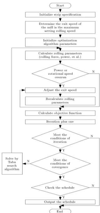
According to the inter-stand thicknesses and ten-sions, parameters like rolling force and power of each stand can be calculated based on the rolling models. The owchart of rolling schedule calculation is shown in Figure 3.
The basic idea of the optimized design is: On the basis of the requirements of equipment and technol-ogy, determine the exit speed of the mill, inter-stand thicknesses, and inter-stand tensions according to the initial data of the incoming material. Calculate rolling parameters (rolling force, motor power, etc.) for the rst time in accordance with known data and judge whether the power or speed goes over the limitation; if they exceed the limit, adjust the exit speed of the mill and recalculate the rolling parameters till they meet the limiting condition; then, calculate objective function. When the calculation is completed and it meets the condition of convergence, check the schedule and output it. If it does not meet the convergence condition, construct Tabu search algorithm and recal-culate until the inter-stand thicknesses and inter-stand tensions that meet the limit of constraint conditions are worked out; meanwhile, make the value of the objective function minimum and check the schedule and output it; otherwise, alarm and nish calculation.
5.3. Tension schedule correction
In the tandem cold rolling, friction coecient of rolls decreases and rolling force decreases with it; thus, strip slipping happens; therefore, it needs to compensate rolling force by means of correcting inter-stand tension. The specic operational process is: Calculate inter-stand tension by multi-objective optimization model; then, correct inter-stand tension through work-roll rolling length of each stand. The calculation formula is as follows:
T0
j= j+1:Tj (j = 1 4); (37)
where, T0
j and Tj are correctional tension and model
calculation tension between stand j and stand j + 1, and j+1 is tension correction coecient determined
by work-roll rolling length of stand j + 1, as shown in Figure 4.
Figure 3. Flowchart of rolling schedule calculation.
Figure 4. The diagram of tension correction coecient.
The corresponding correction coecient can be obtained according to the rolling length of work roll in Figure 4; then, by multiplying it by model calculation tension, revised tension schedule can be obtained.
6. Results and analysis
The proposed multi-objective function optimization algorithm has been successfully applied to a process control system of 1450-mm ve-stand tandem cold mill. The main plant parameters are as shown in Table 1.
Take a type of steel SPCC as an example; the entrance thickness is 2.30 mm, the exit thickness is 0.40 mm, and the width of the nished product is 1000 mm. The comparisons of power distributions and tension distributions between rolling schedule calcula-tion adopting multi-objective optimizacalcula-tion algorithm and traditional experience method are shown in Fig-ures 5 and 6.
It can be seen in Figures 5 and 6 that under the conditions of meeting the technical requirements, the optimized schedule takes advantage of each stand's motor power reasonably and gives full play to the ability of motors. At the same time, rolling force dis-tributions are less balanced in the schedule calculated by traditional method, while there are more balanced rolling force setting in the optimized one. During the rolling process of last stand, a smaller-constant rolling force is maintained, which can play a role in improving atness.
Figure 5. Power distributions for dierent methods.
Figure 6. Force distributions for dierent methods.
Table 1. The main plant parameters of tandem cold mill.
Std. Power (kW)
Rotate speed (rpm)
Gear ratio (i)
Work roll/ coiling block speed
(rpm)
1 3000 300/900 1.91 157/471
2 4200 400/1200 1.91 209/628 3 4200 400/1200 1.357 295/884
4 4200 400/1200 1 400/1200
5 4200 400/1200 1 400/1200
The atness measurements by adopting multi-objective optimization algorithm and traditional expe-rience method are shown in Figures 7 and 8, respec-tively. As can be seen by comparing the two gures, atness measurements by adopting multi-objective optimization algorithm are smooth and have small uctuations, while atness measurements by adopting traditional experience method have larger uctuations, which aect the atness seriously. The results of application validate the feasibility of the model.
7. Conclusions
1. Based on the inuence function method, the atness objective function is established and then
Figure 7. Optimized atness measurement.
rolling-schedule multi-objective optimization model for thin-gauge strip is put forward. Tabu search algorithm is adopted to solve the objective function and a more reasonable rolling schedule is obtained;
2. Tension schedule is corrected according to the rolling length of work roll. The rolling force is compensated in order to avoid slipping of the strip caused by the decrease in friction coecient;
3. The proposed method has been applied to a tandem cold rolling production line. Field application shows that the optimized rolling schedule can give full play to the capacity of equipment. Therefore, the productivity is enhanced. Meanwhile, quality and atness of the product are also improved.
References
1. Fiebig, E. and Zander, H. \Automation of tandem cold-rolling mills", Metallurgical Plant and Technology, 5(3), pp. 88-97 (1982).
2. Bemporad, A., Bernardini, D., Cuzzola, F.A., et al. \Optimization-based automatic atness control in cold tandem rolling", Journal of Process Control, 20(4), pp. 396-407 (2010).
3. Liu, X.X. \Fuzzy multi-object optimization design of rolling schedule on cold continuous rolling mill", Iron and Steel, 35(8), pp. 34-36 (2008) (in Chinese).
4. Wang, D.D., Tieu, A.K., de Boer, F.G., et al. \Toward a heuristic optimum design of rolling schedules for tandem cold rolling mills", Engineering Applications of Articial Intelligence, 13(4), pp. 397-406 (2000).
5. Chen, N.N., Fei, Q. and Hu, H.P. \Research on opti-mization algorithm applied in plate rolling schedule", Applied Mechanics and Materials, 1439(06), pp. 296-301 (2011).
6. Yang, J.M., Che, H.J., Dou, F.P., et al. \Genetic algorithm-based optimization used in rollingschedule", Journal of Iron and Steel Research International, 15(2), pp. 18-22 (2008).
7. Poursina, M., Dehkordi, N.T., Fattahi, A., et al. \Application of genetic algorithms to optimization of rolling schedules based on damage mechanics", Simulation Modelling Practice and Theory, 22, pp. 61-73 (2012).
8. Yang, J.M., Zhang, Q., Che, H.J., et al. \Multi-objective optimization for tandem cold rollingsched-ule", Journal of Iron and Steel Research (Interna-tional), 17(11), pp. 34-39 (2010).
9. Oduguwa, V., Roy, R. and Farrugia, D. \Fuzzy multi-objective optimization approach for rod shape design in long product rolling", Lecture Notes in Articial Intelligence, 2715, pp. 636-643 (2003).
10. Duenas, A. and Petrovic, D. \Multi-objective genetic algorithm for single machine scheduling problem un-derfuzziness", Fuzzy Optimization and Decision Mak-ing, 7(1), pp. 87-104 (2008).
11. Bath, S.K., Dhillon, J.S. and Kothari, D.P. \Fuzzy sat-isfying stochastic multi-objective generation schedul-ing by weightage pattern search methods", Electric Power Systems Research, 69(2-3), pp. 311-320 (2004).
12. Dhillon, J.S. and Kothari, D.P. \The surrogate worth trade-o approach for multi-objective thermal power dispatch problem", Electric Power System Research, 56(2), pp. 103-110 (2000).
13. Liu, S.J. and Wu, B.C. \Optimum design of rolling schedule for tandem cold mill using SLPSO", Ap-plied Mechanics and Materials, 1468(06), pp. 443-446 (2012).
14. Lin, S. and Nan, Y.R. \Optimization of rolling sched-ule in tandem cold mill based on QPSO algorithm", Advanced Materials Research, 1046(06), pp. 165-170 (2011).
15. Qi, X.D., Wang, T. and Xiao, H. \Optimization of pass schedule in hot strip rolling", Journal of Iron and Steel Research, International, 19(8), pp. 25-28 (2012).
16. Hu, X.L., Zhao, Z., Wang, J., et al. \Optimization of holding temperature and holding thickness for con-trolled rolling on plate mill", Journal of Iron and Steel Research, International, 13(3), p. 21 (2006).
17. Purshouse. R.C. and Fleming, P.J. \On the evolution-ary optimization of many conicting objectives", IEEE Transactions on Evolutionary Computation, 11(6), pp. 770-784 (2007).
18. Pires, C.T.A., Ferreira, H.C., Sales, R.M., et al. \Set-up optimization for tandem cold mills: a case study", Journal of Materials Processing Technology, 173(3), pp. 368-375 (2006).
19. Murakami, A.A., Nakayama, M., Okamoto, M., et al. \Optimization of pass schedules for a tandem cold mill", Tetsu to Hagane-Journal of the Iron and Steel, Institute of Japan, 90(11), pp. 953-957 (2004).
20. Pires, C.T.D., Ferreira, H.C. and Sales, R.M. \Adapta-tion for tandem cold mill models", Journal of Materials Processing Technology, 209(7), pp. 3592-3596 (2009).
21. Wang, G.D., Flatness Control and Flatness Theory, Metallurgy Industry Press, Beijing (1986) (in Chinese).
22. Mashayekhi, M., Torabian, N. and Poursina, M. \Con-tinuum damage mechanics analysis of strip tearing in a tandem cold rolling process", Simulation Modelling Practice and Theory, 19(2), pp. 612-625 (2011).
23. Calvo, J., Collins, L. and Yue, S. \Design of microal-loyed steel hot rolling schedules by torsion testing: average schedule vs. real schedule", Metallurgy & Met-allurgical Engineering, 50(8), pp. 1193-1199 (2010).
Biographies
Henan Bu received her BE and MEng degrees in Material Shaping and Control Engineering from North-eastern University in 2011 and 2013. She is currently a PhD student in Materials Processing Engineering in the State Key Laboratory of Rolling and Automation
at Northeastern University. Her research interests are mainly in the area of process automation of tandem cold rolling control system, especially for the research of mathematical model in the rolling process and the optimization of the rolling schedule.
Zhuwen Yan received his MS degree in Materials Processing Engineering from Northeastern University in 2013. He is currently a PhD student in Materials Processing Engineering in the State Key Laboratory of Rolling and Automation at Northeastern University. His research interests are mainly in the area of shape control in the tandem cold rolling control system. Dianhua Zhang received his MS and PhD degrees in Automation Specialty from Northeastern University in 1984 and 2003. He is currently a Professor and
a Tutor of PhD students in Northeastern University, and the Deputy Director of the State Key Laboratory of Rolling and Automation. His research interests are mainly in the areas of material forming process automation, mathematical model of material forming process, and intelligent control of material forming process. He has published more than 120 papers and more than 10 patents, and nished several research projects, including \863," \973" and \NSFC," etc. Shuzong Chen received his PhD degree in Materials Processing Engineering from Northeastern University in 2014. He is currently a Post-Doctoral fellow in the State Key Laboratory of Rolling and Automation at Northeastern University. His research interests are mainly in the area of process control and model specication system in tandem cold rolling.