2334
MODELLING AND SIMULATION: AN INJECTION
MODEL APPROACH TO CONTROLLING
DYNAMIC STABILITY BASED ON
UNIFIED POWER FLOW CONTROLLER
1RAHMANIAR, 2AGUS JUNAIDI, 3GANEFRI, 4ABD. HAMID K, 5NIZWARDI JALINUS, 6JALIUS JAMA
1 Department of Electrical Engineering Faculty of Engineering, Universitas Pembangunan Pancabudi
2,4 Faculty of Engineering, Universitas Negeri Medan
3,5,6 Faculty of Engineering, Universitas Negeri Padang
1[email protected], 2[email protected], 3[email protected]
4[email protected], 5[email protected], 6[email protected]
ABSTRACT
This study aims to determine the effect of UPFC as a Flexible AC Transmission System (FACTS) tool to improve dynamic stability. FACTS is a power electronic device used for various controls on power transmission systems. Power Flow Control, Oscillation Control System can be done by FACTS device. FACTS devices using the Unified Power Flow Controller (UPFC) are modelled to see the performance of dynamic oscillations through software-assisted simulations. Dynamic oscillation occurs due to a temporary disturbance or Short Circuit, causing instability. UPFC devices which are installed on the transmission line. Effect of UPFC to damp oscillation of power system with a model. The injection model is modelled by the active and reactive power supply equation of the injected UPFC to the transmission line. A dynamic oscillation repair is performed by regulating the shunt bus voltage of the reference value and which maintains the dc link on the capacitor voltage. Voltage, The magnitude in the shunt bus, depends on the injected reactive power, where the dc is connected to the capacitor on the UPFC device. The injection model is applied to the simulated effect of UPFC device, showing the simulated effect of UPFC mounting can improve the oscillation caused by disturbances in the power system. Speed Change Oscillations for the generator 1 dan Generator 2, the system without UPFC oscillates for Generator 1, with Over-shoot 6.5x10⁻¹ while using UPFC Over-shoot of 4x6.5x10-10-4. UPFC can reduce the speed change in Generator 6.5x10⁻¹ in about 7.5 seconds; the system returns the equilibrium position (Steady-State).
Keyword: Injection Model, Simulation, FACTS, UPFC
1. INTRODUCTION
Dynamic Oscillation of multi-machine power system. Tested with UPFC installation on the transmission line. UPFC is modelled with state variable equations, then applied UPFC installation. The results of the simulation study show that the installation of UPFC can reduce the oscillation caused by disturbances in the electric power system, and UPFC can control the flow of power on the transmission line by injecting the voltage according to the phase angle. UPFC has the ability to control oscillations due to interference. Utilization of UPFC as a dynamic stability control tool has better performance than controls using LQR controls [1,2,3]. Dynamic modeling and transient modeling of an application of Unified
2335 oscillation well compared to the control of the PI model [6] .The use of parameters with proportional gain (Kp) and integral gain (Ki) on the UPFC control mechanism is used to reduce the oscillation power based on fuzzy tuned adaptive PI controller (FTAPIC) [7]
UPFC can be used with the equation d-q Model. To run a shunt handler, on the UPFC part of UPFC done, first to do a voltage shunt voltage at the right value to connect the link on the capacitor. Voltage, the magnitude in the shunt bus, depends on the injected reactive power (an injection), where the dc Link voltage depends on the active power absorbed by the shunt converter to charge the capacitor on the UPFC device. Therefore the same approach can be achieved in this control system. The control design for the model that has been studied in this paper can give better results than the linear controller. The proposed controller is implemented in the area of two power systems. The increase is similar to the traditional PI controller under different loading conditions. Improved results are better than PI-Controller model [8]. A control system uses UPFC for power flow control. The concept developed is to change reference values such as AC voltage, DC voltage and sequence of converters as simulated serial voltage sources. The pulse width modulation simulation is commonly used to produce pulses injected to both converters. UPFC installation allows controlling several streams through the active power of the channel. Simulation is done using MATLAB and PSCAD software to validate UPFC performance [9]. UPFC independent non-linear control system with new control approach to damp oscillation. The design of the model controller that has been studied can give better results than the linear controller. The proposed controller is implemented in the area of two power systems. The results were compared against traditional PI controllers under different loading conditions. Shows better results than PI-Controller models [10]
Mathematical modelling that can be applied in calculation and regulation of power flows through UPFC control guidance based on indirect matrix converter (UPFC - IMC) in steady state and transient state through a small signal that is extracted to UPFC-IMC. Modelling of UPFC's new structure based on UPFC based on indirect matrix converter (UPFC - IMC) controlled by space vector modulation (SVM), was developed to consider the dynamic study of power systems. Through the modelling is presented, temporary and UPFC-IMC stability performance to be investigated. The UPFC mathematical model based on indirect matrix
converter is formed in a State-space equation to see the workflow of the power flow control process in a steady state and transient state. The investigation results are presented for the steady-state and transient state by simulating the proposed system through MATLAB programming, changing each system parameter from the simulation and visualization results. Modelling tested in the simulation can be used in a variety of studies including load distribution calculations, analyzing and simulating the eigenvalues of power system values for steady state stability testing and dynamic and structured transient stability [11].
2. FACTS DEVICES-UPFC
UPFC is a Flexible AC Transmission System
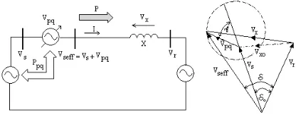
(FACTS) device as a signal that can be used simultaneously (Channel Impedance, Phase Angle and Voltage). UPFC using two converters can build a Simultaneous Voltage Source (Synchronous Voltage Source) that is a controlled Vpq voltage
generating vector with magnitude 0 Vpq Vpq max
[image:2.612.315.523.378.459.2]and phase angle ( pq .) is injected series into a transmission line, as shown in figure 1.
Figure 1: UPFC Concept on Two-Machine Power System
UPFC which is a power electronics device
installed on the transmission line. UPFC consists of exciting transformers (ET) connected series with channels, Boosting transformers (BT) connected parallel to the channel, two voltage source converters or in the implementation referred to as the Voltage Source Converter which is each connected in parallel and series with transmission line through Coupling Transformer, i.e. BT and ET. Both these converters are connected through common link dc, which is dc capacitor storage. This is so that the active power can flow freely through both converters, and each converter can absorb or generate reactive power freely on each output.
2336 The transmission line current flowing through this voltage source undergoes an active and reactive power change among the two converters and ac systems. The reactive power modified at the ac terminal is converted to dc power on the dc capacitor as the active power demand.
Figure 2: Unified Power Flow Controller Using Two voltage source converter
The UPFC injection model used is the current injection model [12]. The model is used to see the effect of UPFC on dynamic stability. Changes of the series voltage injection model to obtain current injection model of series voltage converter voltage
3. UPFC CONTROL MODEL
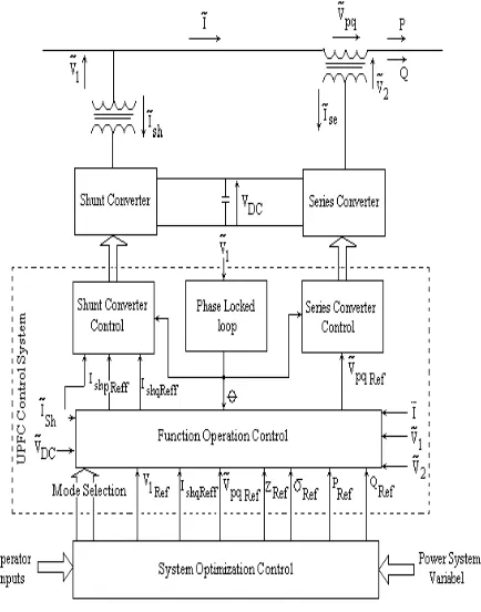
The UPFC control system is by its function divided into two parts, internal control (converter) and functional operational control (function operation). Internal controls operate both converters to produce the desired voltage injection and parallel reactive current. Internal control produces a gate signal to the converter valve so that the inverter output voltage will respond to the IP Ref frequency variable and by the basic control structure.
[image:3.612.96.296.174.336.2]The basic control structure of UPFC is given in block diagram figure 3
Figure 3: UPFC Control Scheme
The serial converter responds to a voltage vector injection request. Parallel converters operate on a closed-loop current control structure that can control active and reactive power components. Parallel reactive power responds directly to the DC input request. Parallel active power is felt by other control loops which act to maintain the voltage level of the dc capacitor and provide the active power needed to inject series voltage.
[image:3.612.318.535.409.685.2]2337 Functional control is defined as the UPFC functional operation mode and the response to produce vpqRef and IqRef internal references as series and parallel compensation to meet the requirements of the transmission system. The functional operation mode and compensation requirements are described by external reference inputs, can be done manually (via a Computer keyboard) by the operator or optimum control is felt automatically. The overall control structure shows internal controls, functional operation controls and automatic system optimum controls with internal and external references shown in figure 4
3.1. Voltage Injection Model
The effects of UPFC on power systems beginning with the analysis of the voltage injection
model series Voltage Source Converter (VSC) as
[image:4.612.316.524.81.190.2]the main functions. The equivalent circuit of the UPFC injection model in figure 5.a with the vector diagram of the equivalent VSC circuit is given in figure 5.b
Figure 5.a: Representation of series VSC Figure 5.b: Vector Diagram of VSC equivalent circuit
A series connected voltage source is placed between the bus-i and the bus-j on the power system. Series voltage source converters can be modelled with series ideal series voltage with
reactance Xs.
Figure
5.a illustrates the idealvoltage Vsand the imaginary voltage sourceVs,
behind the reactance to form the following voltage equation [6]:
s
V
’ =V
s+V
i (2)The series voltage source
V
s can be controlledmagnitude and phase angle:
j i
s
r
V
e
V
(3)The magnitude and phase angle settings are influenced by the time constants and reinforcement, as given in Figure 6 [8].
Figure 6: Block Inverter power control of the UPFC series.
The limit of r as the voltage between the stresses on the i-bus (Vi) and the inject voltage (Vs) is 0 < r < r maks and the controlled phase angle is 0 < < 2. The injection model is equipped with a voltage source with parallel The injection model is equipped with a voltage
V
s in the current sourcess s
s jbV
I and parallel with
s s
X
b 1 is given in
figure 7
Figure 7: Voltage equivalent circuit with the current source.
The current source (Is)is related to the
injection power Sis and Sis:
i( s)
is V I
S (4)
j( s)
js V I
S (5)
Power injection
S
is andS
jssimply written inthe form of the equation as:
cos sin ] [ 2 2 i s i s j i s i is V r jb V r b e V r jb V S (6)
if it is defined ij = i - j,, it will be obtained;
) sin( cos ) sin( ] [ ij j i s ij j i s j i s j sj V V r jb V V r b e V r jb V
S (7)
[image:4.612.95.289.376.462.2]2338
Figure 8: Injection model for VSC series connection
Mathematically equations power injection on bus-i and bus-j;
Psi = rbs Vi2 sin (8)
Qsi = rbs Vi2cos (9)
Psj = - rbs Vi Vj sin(ji + ) (10)
Qsj = - rbs Vi Vj sin(ij + ) (11)
Psi and Qsi are each Active and Reactive power of the bus-i injection while the Psj and Qsj are the Active and Reactive power of the bus-j injection, respectively. 3.2. Mathematical Model of UPFC Injection Model In UPFC, the parallel-source voltage source (Converter-1) has the main function of providing active power that is injected to the network through a series-voltage source (Converter-2), the power equation relationship is written as: Pconv 1 = Pconv 2 (12)
Equation (12) is applied when the losses are ignored, the real power supply by the series voltage source converter is written by the equation: s j i i j ij s conv jx V V V re I V S 2 ' (13)
The active and reactive power supply by the 2-converter is distinguished as; Pconv 2 = rbs Vi Vj sin(i - j + ) – rbs Vi 2 sin Pconv 2 = - rbs Vi Vj cos(i - j + ) + rbs Vi 2 cos + r2 b s Vi 2 The reactive power given or absorbed by Converter-1 is freely controlled by the UPFC and can be modelled as a separate parallel reactive control source, assumed Qconv1 = 0. The addition of equivalent power (Pconv 1 + j0) to the bus-i in the UPFC injection model of the series-voltage source model given in FIG. 5 so that the UPFC Model is given in figure 9. Figure 9: UPFC Injection Model The UPFC power injection equation is: Psi = rbs Vi Vj sin(ij + ) (14)
Qsi = rbs Vi2cos (15)
Psj = - rbs Vi Vj sin(ji + ) (16)
Qsj = - rbs Vi Vj sin(ij + ) (17)
The model shows that the active power exchange of UPFC with the power system is zero, it is expected to minimize the losses of UPFC. Psi and Qsi are Active and Reactive power bus-i injection while Psj and Qsj respectively are an Active and Reactive power of bus-j injection. The model of linearization of equations (14) through (17) is: Psi = Abs Vj0 Vs + A r bs Vi0 Vj (18)
Qsi = bs2 Vi0 Vs cos 0 (19)
Psj = -bs A Vj0 Vs - rbs Vi0 Vj (20)
Qsj = -bs B Vj0Vs - r bs B Vj Vi0 (21)
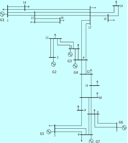
4. EXPERIMENTATION SIMULATION 4.1. Sample Test Data Systems 19 Bus
In the simulation experiment, a system of 19 buses with seven power plants interconnected with a transmission line as shown in figure 10:
2339 4.2 Generator and Machine parameters
The electric power system consists of 19 buses and seven power plants in figure 10 as samples of dynamic stability test without UPFC and using UPFC. The transmission line is connected with a 19 bus, each generator interconnected with the transmission line. The transistor is connected to bus 1, bus 2, bus 3, bus 4, bus 5, bus 6 and bus 7. In bus one the type of generator is a swing generator, as shown in table 1
Table 1 Data Generator and Power Generator Consumption
No
Bus Jenis P(MW) Generator Q(Mvar) P(MW) Generator Consumption Q(Mvar)
1 Swing 2624.78 848.51 132 44
2 Generator 300 104.57 0 0
3 Generator 73 158.17 527 195
4 Generator 432 1903.43 0 0
5 Generator 2191 169.82 609 235
6 Generator 104 438.47 104 15
7 Generator 613 985.42 187 27
8 Load - - 787 581
9 Load - - 424 219
10 Load - - 213 274
11 Load - - 406 188
12 Load - - 718 496
13 Load - - 513 243
14 Load - - 551 214
15 Load - - 491 137
16 Load - - 569 194
17 Load - - 419 354
18 Load - - 227 289
19 Load - - 877 82
The machine parameters for generator 1 to plant seven are respectively given in Table 2
Table 2. Machine parameters
No Gen.
Parameters
Xd Xd’ Xd’’ Xq Xq’ Xq’’ H Kg Tg KA TA Tdo’
(pu) (pu) (pu) (pu) (pu) (pu) (det) (pu) (det) (pu) (det) (det)
1 2.23 0.3 0.26 2.19 0.49 0.22 5.5 20 1 400 0.05 7.9
2 0.92 0.3 0.22 0.51 0.51 0.29 3.5 18 2 100 0.04 5.2
3 0.99 0.2 0.16 0.57 0.57 0.14 3.5 18 2 100 0.02 8
4 1.7 0.25 0.19 1.64 0.38 0.19 5.5 20 1 300 0.04 5.9
5 2.23 0.3 0.26 2.19 0.49 0.22 5.5 20 1 400 0.05 7.9
6 1.7 0.25 0.19 1.64 0.38 0.19 3.5 20 1 100 0.02 5.9
7 1.7 0.25 0.19 1.64 0.38 0.19 3.5 20 1 100 0.04 5.9
2340 4.3. Model Design and Simulation
[image:7.612.133.517.143.636.2]Model design and system simulation, shown in figure 11.7, interconnected generator units are connected via a transmission line. On the UPFC installed transmission line. With the UPFC injection model that is applied to the transmission line for system dynamic stability settings.
Figure 11: Modeling of 19 buses with seven power plants interconnected with transmission line using UPFC
Figure 11 shows the Simulink block of a multi-machine electric power system connected to a
transmission line interconnect system. On the transmission line, UPFC devices are installed.
2341 4.4. Model Generator.
The generator is modelled in the d-q model to obtain the quantity of id and iq and the output data that will be connected to the transmission line. The output of the terminal generator consists of VD and VQ is changed to the model vd and vq. As can be seen in the figure, both outputs vd and vq are proportional to where the equation contains the speed of the Simulink Block.
The generator model arranged in the Simulink model is shown in figure 12.
Figure 12. Linear Generator Simulink block diagram
[image:8.612.316.522.175.393.2]A fast exciter is an excitation system used to provide generator excitation. In figure 11 expressed in blocks diagram. The Simulink Fast Excitation model is shown in figure 13
Figure 13. Fast Excitation model
The governor model of the generator applied to mechanical torque (Tm) is shown in figure 14
Figure 14. Governor Model
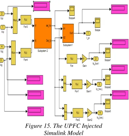
4.5 The UPFC Injected Simulink Model
[image:8.612.93.292.231.434.2]The UPFC injection model with input Vpi,Vqi, Vpj and Vqj produce an Ipi, Iqbus-i, Ipbus-j and Iqbus-j output which will be injected on the transmission line. The UPFC Injection Simulink model is shown in figure 15.
Figure 15. The UPFC Injected Simulink Model
The model shows that the active power exchange from UPFC with the power system is zero; this is expected to minimise losses from the UPFC. Psi and Qsi are the Active and Reactive power of the i-bus injection while Psj and Qsj are the Active and Reactive injection bus-j respectively, shown in figure 16
Figure 16. Injected UPFC Model (Ipi; Iqbus i ; Ipbus j; Iqbus j)
The output of Ipi; Iqbus I; Ipbus j; Iqbus j
[image:8.612.313.523.488.670.2] [image:8.612.116.277.524.592.2]2342 5. SIMULATION RESULTS
5.1. Power flow of experiment 19-Bus
[image:9.612.96.297.208.461.2]Power flow of experiment 19-Bus study without the installation of UPFC is the first step to know the voltage and phase angle of each bus. By using MatPower software tools obtained the data given in Table 3. The data of the load flow result is used to find the value of the network reduction admittance.
Table 3. The data of the load flow result
No
Bus Angle Voltage
1 0.0/rad 1.00+0i
2 -4.55/rad 0.9968-0.0793i
3 -4.77/rad 0.9965-0.0832i
4 -4.66/rad 0.9967-0.0812i
5 28.20/rad 0.8813+0.4725i
6 24.40/rad 0.9107+0.4131i
7 21.43/rad 0.9308+0.3654i
8 21.06/rad 0.9211+0.3546i
9 10.92/rad 0.8768+0.1691i
10 9.85/rad 0.8936+0.1552i
11 -1.90/rad 0.9185-0.0305i
12 -4.46/rad 0.9710-0.0758i
13 -5.06/rad 0.9921-0.0878i
14 -0.47/rad 0.9960-0.0081i
15 -5.11/rad 0.9632-0.0861i
16 -5.72/rad 0.9572-0.0958i
17 -5.36/rad 0.9628-0.0904i
18 -6.69/rad 0.9475-0.1112i
19 -6.83/rad 0.9482-0.1135i
5.2. Eigen Value
The system with stability condition can be analysed by observing Eigen Value, where negative real eigenvalue indicates a stable system so that it is qualified to do controller design. Table 4.5. Is the eigenvalue of the system under open-loop conditions, it can be seen that the real eigenvalue part is negative. The open loop condition is stable but still has oscillations with a certain period; it can be viewed from the response characteristics of the simulation results. The oscillation will be muted by pairing the UPFC injection model so that the overshoot and the time to reach steady-state conditions are better.
Tabel 4. Eigen Value
Eigen value Damping Freq. (rad/s)
-1.88e-001 + 8.04e+001i 2.34e-003 8.04e+001
-1.88e-001 - 8.04e+001i 2.34e-003 8.04e+001
-2.68e-001 + 6.58e+000i 4.07e-002 6.58e+000
-2.68e-001 - 6.58e+000i 4.07e-002 6.58e+000
-3.62e-001 + 1.02e+001i 3.54e-002 1.02e+001
-3.62e-001 - 1.02e+001i 3.54e-002 1.02e+001
-4.94e-001 1.00e+000 4.94e-001
-4.97e-001 1.00e+000 4.97e-001
-7.34e-001 1.00e+000 7.34e-001
-8.23e-001 + 4.50e+000i 1.80e-001 4.58e+000
-8.23e-001 - 4.50e+000i 1.80e-001 4.58e+000
-8.64e-001 + 1.02e+001i 8.43e-002 1.03e+001
-8.64e-001 - 1.02e+001i 8.43e-002 1.03e+001
-9.34e-001 1.00e+000 9.34e-001
-9.52e-001 1.00e+000 9.52e-001
-9.82e-001 1.00e+000 9.82e-001
-9.87e-001 1.00e+000 9.87e-001
-1.08e+000 + 3.36e+000i 3.07e-001 3.53e+000
-1.08e+000 - 3.36e+000i 3.07e-001 3.53e+000
-1.32e+000 + 7.33e+000i 1.77e-001 7.44e+000
-1.32e+000 - 7.33e+000i 1.77e-001 7.44e+000
-2.05e+000 + 1.22e+001i 1.66e-001 1.24e+001
-2.05e+000 - 1.22e+001i 1.66e-001 1.24e+001
-2.27e+000 + 3.78e+002i 6.00e-003 3.78e+002
-2.27e+000 - 3.78e+002i 6.00e-003 3.78e+002
-2.86e+000 + 3.13e+001i 9.09e-002 3.14e+001
-2.86e+000 - 3.13e+001i 9.09e-002 3.14e+001
-7.96e+000 + 5.43e+001i 1.45e-001 5.49e+001
-7.96e+000 - 5.43e+001i 1.45e-001 5.49e+001
-8.57e+000 + 4.07e+002i 2.11e-002 4.07e+002
-8.57e+000 - 4.07e+002i 2.11e-002 4.07e+002
-9.79e+000 + 4.03e+002i 2.43e-002 4.03e+002
-9.79e+000 - 4.03e+002i 2.43e-002 4.03e+002
-1.07e+001 + 2.09e+002i 5.11e-002 2.10e+002
-1.07e+001 - 2.09e+002i 5.11e-002 2.10e+002
-1.16e+001 + 6.03e+002i 1.92e-002 6.03e+002
-1.16e+001 - 6.03e+002i 1.92e-002 6.03e+002
-1.44e+001 1.00e+000 1.44e+001
-1.73e+001 + 1.72e+001i 7.09e-001 2.44e+001
-1.73e+001 - 1.72e+001i 7.09e-001 2.44e+001
-2.24e+001 + 3.46e+002i 6.45e-002 3.47e+002
-2.24e+001 - 3.46e+002i 6.45e-002 3.47e+002
-3.52e+001 + 5.23e+002i 6.71e-002 5.24e+002
-3.52e+001 - 5.23e+002i 6.71e-002 5.24e+002
-4.11e+001 1.00e+000 4.11e+001
-4.12e+001 1.00e+000 4.12e+001
-4.44e+001 1.00e+000 4.44e+001
-4.61e+001 1.00e+000 4.61e+001
-4.80e+001 + 4.99e+002i 9.58e-002 5.01e+002
-4.80e+001 - 4.99e+002i 9.58e-002 5.01e+002
-5.33e+001 + 4.32e+002i 1.23e-001 4.35e+002
-5.33e+001 - 4.32e+002i 1.23e-001 4.35e+002
-5.86e+001 1.00e+000 5.86e+001
-6.24e+001 1.00e+000 6.24e+001
-8.13e+001 1.00e+000 8.13e+001
-9.49e+001 1.00e+000 9.49e+001
-1.05e+002 1.00e+000 1.05e+002
-1.13e+002 1.00e+000 1.13e+002
-1.24e+002 1.00e+000 1.24e+002
-1.38e+002 + 2.27e+001i 9.87e-001 1.39e+002
-1.38e+002 - 2.27e+001i 9.87e-001 1.39e+002
-5.51e+002 + 1.71e+003i 3.06e-001 1.80e+003
2343 5.3. Open Loop and Closed Loop Performance Open Loop performance (without UPFC installation) and Closed Loop (using UPFC) are done through observation of system simulation oscillations, to see how the state of the electric power system when dynamic interference is controlled by UPFC devices. An electrical power increase disruption is given at 0.1 pu during 1-second system operation. UPFC mounted on Transmission Line between bus 1 and bus 15. The use of UPFC has a significant effect on reducing oscillations due to dynamic disturbances.
The response speed () is each observed for
Generator-1 (1), Generator-2 (2), Generator-3
(3) and Generator-4 (4) is shown in figure 17
[image:10.612.323.511.177.381.2]to 20 respectively.
Figure 17: Oscillation Response ()
for generator-1
Figure 17 shows the simulation results without
UPFC and uses UPFC; it can be seen that the
-G1 of electric power system without the UPFC installation oscillates up to 15 seconds while using the UPFC the oscillation state is muted at 6 seconds
Figure 18 oscillations in generator-2 in
open-loop and closed open-loop conditions.
Figure 18: Oscillation Response ()
for generator-2
Figure 17 shows () for generator-2 when
experiencing interference. In open-loop conditions (without UPFC) the system is stable within 7 seconds while using the UPFC system is stable within 15 seconds
[image:10.612.92.298.290.470.2]Figure 19 oscillations in generator-3 in open-loop and closed open-loop conditions
Figure 19: Oscillation Response ()
for generator-3
For generator 3, Response when the system
has an oscillation without UPFC installation, it occurs for up to 10 seconds.
[image:10.612.330.515.459.649.2]For figure 20, it shows the oscillation response of the generator-4 electric power system in the open-loop and closed loop conditions as follows:
Figure 20: Oscillation Response ()
for generator-4
Figure 20 shows system oscillations before and after UPFC installation. When given a disturbance simulation given to the plan, the oscillation without using oscillation reaches steady state at 15 seconds, while using the UPFC the system oscillation can be muted at 8 seconds.
[image:10.612.92.295.560.715.2]2344 The UPFC Injection Model for the dynamic oscillation control proposed was evaluated to see the UPFC's ability to reduce the power system oscillations. The UPFC injection method can improve the power system oscillation. The UPFC installed in the transmission line can significantly reduce the oscillation of the electric power system [9,13,14]. The UPFC injection model proposed in the study can reduce overshoot and oscillation time from the system repaired by UPFC devices when dynamic interference occurs in the electric power system. The result of real eigenvalue observation is the negative value of open loop condition system in stable condition but still have oscillation with a certain period; it can be observed from the response characteristic of the simulation result. The oscillation will be muted by pairing the UPFC injection model, so that overshoot and time to achieve steady-state conditions are better.
The concept of power station dynamic stability control, has been proposed through SMIB system control using PSS and optimal control. From the studies that have been investigated, oscillations can be muted within 5 seconds [15]. Utilization of optimal control with optimal gain if applied to a multi-machine system has an impact on the need for sensors to the optimal gain requires a large enough cost. because For the interconnection system, the parameter data to be censored is located in a remote place. Through UPFC which is only installed in one area on the transmission line can overcome the problem optimally
7. CONCLUSION
This paper discusses the development of the UPFC injection model on the transmission line. The model developed using Mat Power software and Simulink-Matlab Software. The test results show that the installation of UPFC on the transmission line can reduce the oscillation and accelerate the dynamic oscillation to achieve a steady state.
Oscillation Response () for generator-1,
generator-2, generator-3 and generator-4 without UPFC installation and using UPFC shows good performance in reducing overshoot and dynamic oscillation. The system without UPFC oscillates for
Generator-1, with Over-shoot 6.5x10⁻¹ while using
UPFC Over-shoot of 4x10⁻⁴
. The system in an
open-loop and closed loop state has a difference of 6 seconds in reducing oscillation for the steady state in generator-1. Damping Oscillation in generator-2 in the closed loop condition of 7 seconds reaches a steady state while the open-loop state and the oscillation reach 15 seconds to the
steady state. Likewise for generator-3 and generator-4 oscillations can be muted within 10 and 8 seconds respectively.
So it can be concluded that for open-loop conditions (without UPFC) and closed-loop (using UPFC) dynamic disturbances in the electric power system can be improved through the installation of UPFC on the electric power system. The test results show that the UPFC injection model applied to the transmission line can improve overshoot and reduce system oscillation
REFERENCE
[1]. P. K. S. Arabi, "A Versatile FACTS Devices
Model for power Flow and Stability
Simulations" IEEE, vol. 11, no. 4, 1996. pp.
1944-1950.
[2]. Parvathy.S, K.C.Sindhu Thampatty, “Dynamic
Modeling and Control of UPFC for Power
Flow Control”, Procedia Technology, 2015
[3]. Rahmaniar, Agus Junaidi,” Modelling and
Simulation: A Comparison of LQR Control and Unified Power Flow Controller for
Dynamic Stability Improvement”,
International Journal of Engineering Research and Technology. ISSN 0974-3154, Volume 12, Number 7, 2019, pp. 1033-1038.
[4]. H. Wang, "A Unified Model For Analysis Of
FACTS Devices In Damping Power System Oscillation Part II: Multi-Machine Power
Systems," IEEE transaction On Power
Delivery, 1998.vol. 13 No 4.
[5]. L Gyugyi, Narain G.H, “Understanding
FACTS Concept and Technology of Flexible AC Transmission Systems,2000 IEEE”. Press,
[6]. J. Guo,” An Improved UPFC Control for
Oscillation Damping”, IEEE Transactions On Power Systems, 2009.Vol. 24, No. 1.
[7]. M. Sebaa, O. Bekhechi, A. Chaker,”A Fuzzy
Tuned Adaptive PI Controller Based UPFC to Improve Power Oscillations Damping in Multi
Machine Power System”, International Review
on Modelling and Simulations (I.RE.MO.S.), Vol. 8, N. 3 2015 ISSN 1974-9821.
[8]. G. I. R. H. I. Shaheen, S. J. Cheng, "Optimal
Location and Parameters Setting of UPFC based on GA and PSO for Enhancing Power
System Security under Single Contingencies,"
2008, IEEE.
[9]. Kalyani T, G. Tulasiram Das Simulation Of
Real And Reactive Power Flow Control With Upfc Connected To A Transmission Line”,
Journal of Theoretical and Applied
2345
[10].P. C. P. Jose.P.Therattil, "Damping of Power
System Oscillations using an Advanced
Unified Power Flow Controller" 2011, IEEE
PEDS,
[11].E. B. Farzad Mohammadzadeh Shahir,
"Dynamic Modeling of UPFC based on
Indirect Matrix Converter," 2012, IEEE.
[12].F. J. S. H.F Wang, "A Unified Model for
analysis of FACTS devices in Damping Power Systems Oscillation part III: Unified
Power Flow Controller," IEEE, vol. 15 no 3,
2000, pp. 978-983.
[13].Hussain, Malek F., “Performance
Improvement of Power System Stability by Using Multiple Damping Controllers Based
on PSS and the UPFC” International Journal
of Engineering and Technology (IJET), 2013.
[14].Prasad Vishnu M, Sanjeev Jarariya,” Stability
Enhancement Of Power Transmission Using
Upfc With Fuzzy Logic Controller,”
International Journal Of Engineering Sciences & Research Technology, 2018.
[15].Agus Junaidi, Abdul Hamid, “Design of
Simulation Product for Stability of Electric Power System Using Power System Stabilizer
and Optimal Control” IOP Conf. Series: