2019 International Conference on Artificial Intelligence and Computing Science (ICAICS 2019) ISBN: 978-1-60595-615-2
Analysis and Implementation of the Control Algorithms of the Smart Car
Shi-peng LIU, Xiao-ying YANG and You-ling YU
*School of Electronic and Information Engineering, Tongji University, Shanghai 201804,China
*Corresponding author
Keywords: Smart car,Camera image recognition, Path decision, Obstacle avoidance.
Abstract. This paper introduces the design and implementation of a smart car system that can orient the illuminating beacon. After debugging and testing, the system has good accuracy and speed. Combining image recognition, path decision, adaptive obstacle avoidance and other control algorithms, the system is an original model and has certain practical significance for vehicle electronic technologies.
Introduction
In recent years, automobile and technology companies have continuously innovated in-vehicle electronic technologies. The development trends are characterized by security, networking, and intelligence[1]. Intelligent car, also known as wheeled mobile robot, is the integration of the environmental awareness, planning and decision-making, and automation-running[2]. This paper designs a smart car based on MDK60DN512ZVLQ10 (K60) and OV7620 camera for directional movement of illuminating beacons. The system combines image recognition, speed control, straight line fitting algorithms and so on, which have practical significance for the smart car control.
System Structure
Overview of Hardware Design Scheme
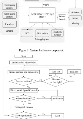
The Microcontroller Unit(MCU) of the smart car system is two master-slave cooperated K60. The sensors are two OV7620 cameras and two incremental encoders. The front-facing camera is used to obtain the position of the illuminating beacon and the obstacle, and the right-facing camera is used to search for the illuminating beacon in the right area, assisting the car to judge the direction autonomously. The encoder is used to obtain the current speed and mileage.
After receiving and processing the completed image, the master K60 combines the slave K60 information to obtain the target speed and the target angle. According to the current speed fed back by the encoders, the motor speed control and steering control are realized by pulse width modulation (PWM), in order to achieve the directional movement of the smart car to the luminous beacon.
The system adopts LCD display, dial switch and Bluetooth module for debugging. The LCD display can output camera image and various position parameters. The dial switch is used to change the running mode of the car, and the Bluetooth module is used to remotely control the car.
Figure 1. System hardware component.
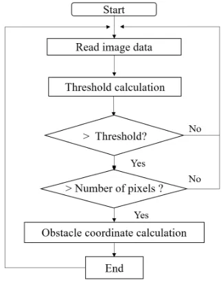
Figure 2. Flow chart of the control system.
Overview of Control Design Scheme
[image:2.612.169.443.109.500.2]The control system adopts modular programming ideas, including six modules, as shown in Fig.3. The flow chart of the software control system is in Fig.2.
Figure 3. Six modules of the system.
Design of Control Algorithm
Camera Image Capture
Therefore, the system asynchronously capturing image while ensuring that the main control memory is sufficient. The specific algorithm is: preset the buffer areas A and B access the data, while the CPU is processing the data of the buffer A, the camera storing the data in the buffer B, after the processing is completed, the data in buffer B begins to be processed, the camera stores the data in buffer A, and so on, as is showed in Fig.4.
[image:3.612.126.505.136.266.2]
Figure 4. Camera image capture process. Figure 5. Camera data line selection.
Taking into account the limited CPU memory, the system takes part of the image information for processing through the line selection. The OV7620 camera image array is 320*240, and the image is most concentrated and effective in about 120 lines.
Therefore, we adjust the position of the camera to ensure the farthest beacon in the 120th line of the camera view. The system selects 100 lines of data in the camera image for preliminary processing. When the line is selected, it is sparse in the vicinity and dense in the distance, avoiding the loss of image information in the distant place. The pixels in the lines greater than 130 are abandoned. In this way, the image to be processed is reconstructed, as is shown in Fig.5.
Image Processing
Beacon Search. In order to reduce the interference of light and noise on the site, binarization and mean filtering are used when processing pixels.
Since the gray value of the illuminating beacon light is above 250, the system directly uses 250 as the binarization threshold. Then the system traverses the target image by using the upper, middle and lower three-point mean filtering method to find all pixels larger than the threshold. The horizontal and vertical coordinates are respectively summed, and the number of pixel points is recorded. After the traversal is completed, the average value is calculated to obtain the specific orientation of the beacon. The block diagram is shown in Fig.6.
[image:3.612.138.280.508.719.2][image:3.612.324.485.515.721.2]
After texting, the filtering method combined with binarization to position beacon can greatly improve the recognition accuracy.
Threshold Adaptive Obstacle Recognition. In order to eliminate the interference of the site and improve the accuracy of obstacle recognition, the system reduces the traversal range of each image, so that the car only detects and avoids the area that may cause obstacles in front of the vehicle body, that is, “trimming the image”, and getting appropriate obstacle window.
During the travel of the car, the obstacle is white non-illuminated beacons, and its gray value changes with the environment. A fixed gray value cannot be used as a threshold. In order to adapt to the changes of the environment, the system uses the average gray value of the obstacle avoidance window, plus an adjustable error as the threshold value, which changes dynamically. The block diagram is shown in Fig.7.After verification, it has achieved a better result.
Speed Control Strategy
Speed control is especially critical for beacon smart car. When the car approaches or leaves the beacon, turns to find beacons, avoids obstacles, etc., it must go through the process of deceleration or acceleration, and the car needs to achieve both stability and rapidity.
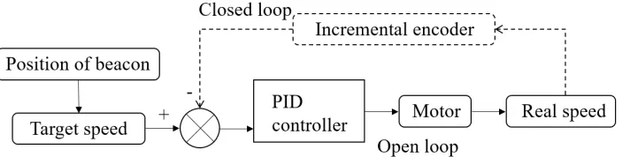
Open-loop and PID-closed-loop control are classic algorithms for speed control, as is shown in Fig.8. [3] Digital PID is adopted in the microcontroller, that is, Eq.1. After testing, we get a set of applicable parameters:
[image:4.612.140.496.357.446.2]u k = + ∑ + [ − − 1 ] (1)
Figure 8. Open and closed loop speed control.
In this smart car system, instead of simple PID control or fuzzy PID control[3], it combines PID control, open loop control, inertia deceleration, differential turn and other strategies for flexible control: the acceleration process adopts full duty cycle open-loop control, the deceleration process, that is, when approaching the beacon, adopts PID control, but the deceleration interval size is adaptive, and the deceleration mode is started according to the current speed of the encoder feedback, so that the car arrives at the beacon at a speed of 3.5m/s, the turning process is controlled by the open loop of 1.6m/s. The speed control strategy is shown in Fig.9.
Route Planning
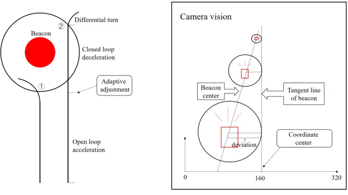
Figure 9. Diagram of the car turning. Figure 10. Dynamic changes in the view of camera.
Straight Path Fitting. Since the camera can only calculate the center position of the beacon, and cannot directly align the beacon along the tangent line. Therefore, the beacon coordinates should be used as a reference, and the deviation is added to obtain the tangential coordinates of the beacon.
In the view of the camera, when the car moves toward the beacon along the tangential line from far to near, the beacon is getting bigger and bigger. The deviation between the center and the tangent line of the beacon is also changing dynamically. Therefore, the vertical distance between the car and the beacon (the row coordinates in the view of the camera) determines the magnitude of the deviation, as is shown in Fig.10.
In order to get the function of the deviation with the vertical distance from the car to the beacon, we carefully tested and get the data of distances and deviations, using MATLAB piecewise first-order linear fitting to obtain Eq.2,3,4,5, where target_H is the row coordinate of the beacon in the camera's view.
147.8 − 0.68 × target_H 0 ≤ target_H < 32 (2)
deviation= 200.9 − 2.13 × target_H 32 ≤ target_H < 66 (3)
179.2 − 1.93 × target_H 66 ≤ target_H < 146 (4)
184.9 − 2.13 × target_H 146 ≤ target_H ≤ 160 (5)
Scene Design and Analysis of Results
Scene and Material Description
[image:5.612.163.464.637.715.2]The test area of the smart car system is a 5*7 ㎡ blue advertising cloth with 5~7 beacon placed thereon, and the control box sends out a control signal to make the beacon illuminate randomly, as in Fig.11.
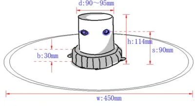
The beacon is shown in Fig.12,13. It can send red, 10Hz infrared and ultrasonic navigation signals. The induction coil is placed under the beacon. When the magnetic label mounted on the smart car passes through the coil, the coil generates an induced pulse signal. The beacon receives and amplifies the pulse signal and sends it to the control box. The control box sends a signal to extinguish the beacon and illuminate the next one. [4]
[image:6.612.107.307.149.258.2] [image:6.612.364.511.162.260.2]
Figure 12. The specifications of the beacon. Figure 13. The working principle of the beacon.
Results Analysis
The smart car system for directional movement of the beacon is shown in Fig.14. When the smart car is facing the beacon, the binarized image is shown in Fig.15.
Figure 14. The completed smart car system. Figure 15. The binarized image.
When the beacons are randomly set, the time required for the smart car to extinguish all the lights is shown in Table 1.
Table 1. Test results.
Number of test 1 2 3 4 5 Right
camera
On[s] 16.21 15.21 12.84 16.40 15.83 Off[s] 19.34 18.87 21.25 16.78 20.61
The time the smart car system uses to turned off the beacon is closely related to the battery power, tire friction, route path, etc. It can be seen from the table that the system has a high light-off rate and accuracy, and the directional motion effect is good. After self-determination is added, the efficiency of extinguishing beacon is significantly higher, because unnecessary paths for finding lights are reduced.
Conclusion
[image:6.612.116.513.329.484.2] [image:6.612.189.426.532.586.2]has satisfying results. The smart car system can be used as the original model and reference for the innovation and development of automotive electronics technology, and has practical significance.
Acknowledgement
This research was financially supported by(1)Research on Intelligent Control Algorithm of Super High-rise Complex Multi-Energy Air Conditioning System (2)Jiangsu Provincial Housing and Urban-Rural Construction Department - Program on the Next-Generation Smart Green Building.
References
[1] Li Lin. Analysis of Automotive Electronic Technology and its Development Trend [J]. Inner Mongolia Science Technology and Economy, 2008, (1): 38-40.
[2] L. Zhang and Q.H. Song, “Design of Smart Car Servo system Based on Camera”, Advanced Materials Research, Vols. 383-390, pp. 5923-5927, 2012.
[3] Zhang Jia-hua, Xu Lian-qiang, Wu Ying-chun. Design of speed control system based on fuzzy-PID control for intelligent vehicle [J]. Information Technology, 2012, (10): 181-183.