© 2016, IRJET | Impact Factor value: 4.45 | ISO 9001:2008 Certified Journal
| Page 366
Hardware Performance Comparison of PI and Space Vector PWM
Techniques for Speed Ripple Minimization in Permanent Magnet
Synchronous Motor with and without Iterative Learning Control
1
N.Subha Lakshmi,
Department of EEE,
Sri Krishna college of Engineering and technology, Coimbatore
1
[email protected]
---******---
Abstract— Permanent-magnet synchronous motor (PMSM) drives are widely used in high-performance industrial servo applications where torque smoothness is an essential requirement. However, one disadvantage of PMSM is parasitic torque pulsations, which induce speed pulsations that deteriorate the drive performance particularly at lower speeds. This paper propose the proportional plus integral controller (PI)working in transient state in parallel with Iterative learning control (ILC) working in steady state with Space Vector Pulse Width Modulation (SVPWM) to suppress the speed ripples in PMSM driven by field oriented control. The speed controller compares the reference motor speed with actual motor speed, and produces the reference current iq ref value which in turn
reduces the speed error. According to iq ref value SVPWM pulses
are produced and given to the three phase voltage source inverter. The advantages and effectiveness of the proposed method for speed ripple reduction is designed, analysed and simulated using simulink library in MATLAB R2009a and implemented in hardware using TMS320F2812. The results obtained from PEC16DSMO1 show the significant reduction in speed ripples using proportional plus integral controller (PI) plug in Iterative learning control (ILC) with Space Vector Pulse Width Modulation (SVPWM). This method shows better speed ripple reduction in comparison with the conventional method.
Keywords— Permanent Magnet Synchronous motor (PMSM), Torque ripple, Field oriented Control (FOC), Proportional plus Integral Controller (PI), Iterative learning control (ILC), Space Vector Pulse Width modulation (SVPWM)
I. INTRODUCTION
Permanent magnet synchronous motors (PMSM) are widely used in low and mid power applications such as computer peripheral equipments, robotics, adjustable speed drives and electric vehicles. PMSMs are still favoured for high-performance servo applications because of their high efficiency, power density and torque-to-inertia ratio, which make them a suitable choice for variable-speed direct-drive applications. However, the main disadvantage of PMSMs is the parasitic torque pulsations. Presence of these torque pulsations results in instantaneous torque that pulsates periodically with rotor position. These pulsations are
reflected as periodic oscillations in the motor speed.These oscillations produce undesirable mechanical vibration on the load side.
The various sources of torque pulsations in a PMSM can be minimised by both motor design and control schemes which have been proposed in literature[5] . Smooth torque is obtained by tracking of a modified current reference with electrical time period. To achieve constant torque repetitive reference current signal is tracked and is controlled in a field oriented PMSM drive.[7]
Space Vector PWM (SVPWM) refers to a special switching sequence for the three-phase power inverter. It generates less harmonic distortion in the output voltages and or currents applied to the phases of an AC motor and to provide more efficient use of supply voltage compared with sinusoidal modulation technique.[1,14]
This paper presents an application of proportional integral controller with plug in iterative learning control to minimise the speed ripple associated with the field oriented control when used in control of a PMSM. A SVPWM based FOC with iterative learning control and PI is proposed to produce an effective selection of the stator voltage vector to obtain smooth torque performance. The advantage of FOC is that it increases efficiency, letting smaller motors replace larger ones without sacrificing torque and speed. The ILC is known for its best anticipatory character and ability to ensure the compensation for repetitive external disturbances by learning based on previous iterations without further modelling burdens.
II. OVERVIEWOFFIELDORIENTEDCONTROL
© 2016, IRJET | Impact Factor value: 4.45 | ISO 9001:2008 Certified Journal
| Page 367
represented by a vector. This control is based on projections which transform a three phase time and speed dependent system into a two co-ordinate (d and q co-ordinates) time invariant system. These projections lead to a structure similar to that of a DC machine control. Field orientated controlled machines need two constants as input references: the torque component (aligned with the q coordinate) and the flux component (aligned with d co-ordinate). As FOC is simply based on projections, the control structure handles instantaneous electrical quantities. This makes the control accurate in every working operation (steady state and transient) and independent of the limited bandwidth mathematical model. The FOC thus solves the classic scheme problems, in the following ways:
1.The ease of reaching constant reference (torque
component and flux component of the stator current).
2.The ease of applying direct torque control, because in
the (d,q) reference frame the expression of the torque is:
By maintaining the amplitude of the rotor flux (ΨR) at
a fixed value, we have a linear relationship between torque and torque component (isq). We can then control
the speed by controlling the speed component of stator current vector. The block diagram of conventional FOC of PMSM is shown in Fig. 1.
LOAD PMSM Clark transformation Park transformation Hysteresis PWM
Speed and position sensing 3 INVERTER Park inverse transformation i PI PIiq PI + i sdref=0 ref m i i ia ib SHAFT RECTIFIER AC SUPPLY V dc Theta isqref id + + i
Fig.1 Block Diagram of PMSM drive with FOC using conventional PI controller
III.PROPOSEDSYSTEM
The proposed iterative learning control (ILC) controller is applied in parallel with the conventional
proportional- integral (PI) speed controller, which compares the actual speed wm with the reference speed
wref provides the main reference current isqref. During
steady state, the proposed ILC controller generates a compensation current iqs*that together with the main reference current iqo* which is utilized to minimize the speed ripples. Conventional PI current controllers are used in the inner control loops to generate the control voltages to shape Space vector pulse width-modulated (SVPWM) signals. Test results obtained shows improvement in the steady-state speed response and therefore validate the effectiveness of both ILC and PI controllers. During the transient state, the ILC is made inactive and is provided only by the PI speed controller output, when steady state is reached, the ILC is applied and it provides the additional compensation term to so as to minimize the speed ripples. The performance of the drive system using the ILC scheme is compared with the scheme using only the PI controller. The block diagram of proposed FOC with the Iterative Learning based controller for the PMSM drive is shown in the figure 2.
LOAD PMSM Clark transformation Park transformation Space vector Modulation PWM
Speed and position sensing
3 INVERTER Park inverse transformation i PI PI iq Iterative learning controller (ILC) + i sdref=0 ref m i i ia ib SHAFT RECTIFIER AC SUPPLY V dc Theta i sqref id + i PI * qs i ++ + * qo i
Fig.2 Proposed Block diagram of PMSM driven by Field Oriented Control using ILC-SVM Controller
A. Space Vector Pulse Width Modulation
© 2016, IRJET | Impact Factor value: 4.45 | ISO 9001:2008 Certified Journal
| Page 368
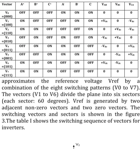
approximates the reference voltage Vref by a combination of the eight switching patterns (V0 to V7). The vectors (V1 to V6) divide the plane into six sectors (each sector: 60 degrees). Vref is generated by two adjacent non-zero vectors and two zero vectors. The switching vectors and sectors is shown in the figure 3.The table I shows the switching sequence of vectors for inverters.
V2
V1
V6
V5 V4
V3
VC
2 1
3
4 5
[image:3.595.33.280.102.365.2]6
Fig.3 Switching vectors and sectors
To implement the space vector PWM, the voltage equations in the abc reference frame can be transformed into the stationary αβ reference frame that consists of the horizontal (α) and vertical (β) axes, as a result, six non-zero vectors and two zero vectors are possible. Six nonzero vectors (V1 - V6) shape the axes of a hexagonal as depicted in Fig 3 and feed electric power to the load or DC link voltage is supplied to the load. The angle between any adjacent two non-zero vectors is 60 degrees. Meanwhile, two zero vectors (V0 and V7) are at the origin and apply zero voltage to the load. The eight vectors are called the basic space vectors and are denoted by V0, V1, V2, V3, V4, V5, V6, and V7. The same transformation can be applied to the desired output voltage to get the desired reference voltage vector Vref in the d-q plane. The objective of space vector PWM technique is to approximate the reference voltage vector Vref using the eight switching patterns.
TABLE I SWITCHING VECTORS FOR INVERTER
B. Iterative Learning Control
Iterative learning control is an approach to improve the tracking performance of a system that operates repetitively over a fixed time interval. It is basically an error correction algorithm and a memory that stores previous control effort and error and computes the new control effort based on that information. The advantages of ILC is the invariance of the system dynamics is maintained. The output can be measured within a small specified noise level.[1,8,9]The formula used for ILC is given in the equation 2 and the block diagram is shown in the fig 4.
Where i=1,2,3…….is the iteration number; is the control signal, namely reference compensation q-axis current generated from ILC; is the speed error signal; is the forgetting factor; is the previous cycle feedback; is the current cycle feedback.
MEM I PMSM
DRIVE MEM 2
+
-+ +
+
1
) ( *
m t
) (
mt
) (
1t
ei ei(t)
) (
1t
ui
[image:3.595.78.262.354.504.2]) (t ui
Fig. 4 Block diagram of ILC
C. PI Controller Tuning
The speed loop PI controller compares the reference speed with actual speed and produces the reference current isqref. The current loop PI controllers compares
the actual current with reference current and produce iq
and id current respectively. PI tuning is done by trial and
error method.
IV.HARDWARERESULTSANDDISCUSSION
A. OUTPUT CURRENT WAVEFORM FOR 50%LOADING
The figure 5 shows the output current waveform at 50%loading.The current value is 3.3A at 2300 rpm. The parameters are
X-Axis –Time in ms,(1 div=5ms)
Vector A+ B+ C+ A- B- C- VAB VBC VCA
[image:3.595.342.557.391.523.2]V0
={000} OFF OFF OFF ON ON ON 0 0 0
V1
={100} ON OFF OFF OFF ON ON +Vdc 0 -Vdc
V2
={110} ON ON OFF OFF OFF ON 0 +Vdc -Vdc
V3
={010} OFF ON OFF ON OFF ON -Vdc +Vdc 0
V4
={011} OFF ON ON ON OFF OFF -Vdc 0 +Vdc
V5
={001} OFF OFF ON ON ON OFF 0 -Vdc +Vdc
V6
={101} ON OFF ON OFF ON OFF +Vdc -Vdc 0
V7
© 2016, IRJET | Impact Factor value: 4.45 | ISO 9001:2008 Certified Journal
| Page 369
[image:4.595.319.574.103.245.2]Y axis-(I1,I2,I3)- current in Amps,( 1div = 2A)
Figure 5 Waveform of Output currents ( Ia,Ib,Ic =3.3A) at speed 2300rpm
B. OUTPUT VOLTAGE WAVEFORM FOR 50%LOADING
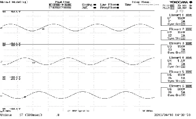
The figure 6 shows the output voltage waveform at 50%loading.The voltage value is 100V at 2300 rpm. The parameters are
X-Axis –Time in ms,(1 div=5ms)
[image:4.595.37.254.114.254.2]Y axis-(U1,U2,U3)- Voltage in volt,( 1div = 150V).
Figure 6 Waveform of Output Voltage ( Va,Vb,Vc =100V) at
C. DYNAMIC SPEED WAVEFORM OF PI-SVPWM
[image:4.595.46.244.432.552.2]The figure 7 shows the dynamic speed response of PI-SVPWM at the speed range of 1000 rpm to 4000rpm
Figure 7 Dynamic speed waveform of PI-SVPWM
D. WAVEFORM OF SVPWM,LINETO LINE VOLTAGE
WITHOUT FILTERING AND WITH FILTERING
The figure 8 shows the SVPWM pulses,inverter output voltage for each phase without filtering and with filtering.The voltage value is 220V at 4000 rpm. The parameters are
X-Axis –Time in ms,(1 div=5ms)
Y axis-(U1,U4,U5)- Voltage in volt,( 1div = 150V).
Figure 8 Waveform of SVPWM , line to line voltage without filtering and line to line voltage with filtering.
E. DYNAMIC SPEED WAVEFORM OF PI-ILC-SVPWM
[image:4.595.324.551.448.625.2]© 2016, IRJET | Impact Factor value: 4.45 | ISO 9001:2008 Certified Journal
| Page 370
Figure 9 Dynamic speed waveform of PI-ILC-SVPWM
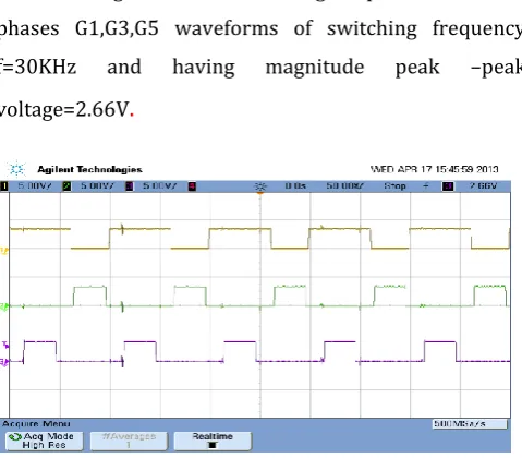
F. WAVEFORM OF GATEPULSES FOR THREE PHASES
G1,G3,G5
The figure 10 shows the gate pulses for three phases G1,G3,G5 waveforms of switching frequency f=30KHz and having magnitude peak –peak
[image:5.595.38.270.93.266.2]voltage=2.66V
.
Figure 10 Gate pulses waveform for phases G1,G3,G5
G. WAVEFORM OF GATEPULSES FOR THREE PHASES
G4,G6,G2
[image:5.595.310.568.106.277.2]The figure 11 shows the gate pulses for three phases G1,G3,G5 waveforms of switching frequency f=30KHz and having magnitude peak –peak voltage=2.66V
.
Figure 11 Gate pulses waveform for phases G4,G6,G2
TABLEII
COMPARITIVERESULTSOFCONTROLTECHNIQUESOFPMSM
FIELD ORIENTED
CONTROL SPEED RIPPLE FACTOR (%)
FOC with ILC-SVM 12.3
FOC with PI-ILC-SVM 2.6
From the above table it is inferred that the percentage of ripples obtained by each case are shown and compared, by PI controller it is 12.13% of ripple, and by PI-ILC-SVPWM based controller the ripple is 2.6%. Thus in PI-ILC-SVPWM based controller has better performance by reducing 9.53%.
V. CONCLUSION
Speed pulsations are less in case of PI-Iterative learning controller. It is clear that a PI-ILC based speed controller achieves the minimum speed ripple in both transient state and steady state respectively than with only PI based speed controller. The results obtained from PI-ILC based speed demonstrate fast and satisfactory response both in transient state and steady state with less speed ripples.
VI.REFERENCES
[1]
Adhavan.B, Kuppuswamy.A, Jayabaskaran.G, Jagannathan. V
(2011) “Field oriented control of Permanent Magnet Synchronous Motor (PMSM) using fuzzy logic controller”, Recent Advances in Intelligent Computational Systems (RAICS), IEEE, pp.587-592. [image:5.595.38.278.338.548.2]© 2016, IRJET | Impact Factor value: 4.45 | ISO 9001:2008 Certified Journal
| Page 371
on Systems, Man and Cybernetics –part c:application andreviews, vol.37, no.6, pp.1099-1121.
[3] Bimal. K. Bose (2002), “Modern Power Electronics and AC- Drives”, PHI Learning Private Limited.
[4] Favre E, Cardoletti L, Jufer M ( 1993),“Permanent Magnet Comprehensive Approach to Cogging Torque Suppression”, IEEE Transactions on Industry Applications, pp.1141-1149.
[5] Gulez K, Adam A.A, Pastaci H ( 2008),“ Torque Ripple & EMI Noise Minimization in PMSM Using Active Filter Topology & Field–Oriented Control”. IEEE Transactions on Industrial Electronics, vol.55, no.1, pp.251-257.
[6] Jahns T.M, Soong W.L ( 1996),“ Pulsating Torque Minimisation Techniques for Permanent Magnet AC Motor Drives - a review”. IEEE Transactions on Industrial Electronics, vol.43, no.2, pp.321-330.
[7] Juria Mat Lazi, zulkifilie Ibrahim, Marizan Sulaiman, Irma Wani Jamuludin, Yusuf Lada (2011),“Performance Comparison of SVPWM and Hysterisis Current Control for Dual Motor Drives”. IEEE Transaction on Applied Power Electronics, pp.75-80
[8] Mattavelli P, Tubiana L, Zigliotto M ( 2005), “Torque Ripple Reduction in PM Synchronous Motor Drives Using Repetitive Current Control”. IEEE Transactions on Power Electronics, vol.20 , no.6, pp.1423-1431.
[9] Qian W, Panda S.K, Xu J.X ( 2005), “Speed Ripple Minimization in Permanent Magnet Synchronous Motor Using Iterative Learning Control”. IEEE Transactions on Energy Conversion,
vol.20, no.1, pp.53-61.”
[10]Qian W, Panda S.K and Xu J.X ( 2004),“Torque Ripple Minimization in PM Synchronous Motors Using Iterative Learning Control”, IEEE Transactions on Power Electronics, vol.19, no.2, pp.272-279.
[11]Rahmi M, Abbaszadeh K, Radanb A ( 2010), “Torque Ripple Suppression of Surface Mounted Permanent Magnet Synchronous Motor Using Harmonic Injected Currents”.1st power electronics and drives systems &technologies conference, pp.279-283.
[12]Rivas D, Moran L, and Jose R.E (2003), “Improving Passive Filter Compensation Performance With Active Techniques”,
IEEE transaction on power Electronics, pp.161-170.
[13]Rahimi M, Abbaszadeh K, Radan A(2010), “Torque ripple suppression of surface mounted permanent magnet synchronous motor using Harmonic Injected Currents”. IEEE Transaction on Power Electronics and Drive Systems, pp.279-283.
[14]Shin-Hung Chang,Pin-Yung Chen (2010)“Self–tuning Gains of PI Controllers for Current Control in a PMSM”. IEEE transaction on power Electronics, pp.1282-85.
[15]Texas instruments, Europe “Field Oriented Control of Three Phase AC Motors ”.
[16]www.motioncontrol.com
[17]www.mathworks.com