International Journal of Emerging Technology and Advanced Engineering
Website: www.ijetae.com (ISSN 2250-2459, Volume 2, Issue 1, January 2012)137
Optimization of Repeater Spacing for Terrestrial and
Undersea Fiber Optic Communication
1
T. Sabapathi ,
2M. S. Ajay Gautham,
3R. Paranthaman
Mepco Schlenk Engg. College,Sivakasi-626005, Tamilnadu ,India
[email protected] [email protected]
Abstract- Repeater spacing in fiber optic communication is optimized taking into consideration various parameters such as fiber attenuation, Stimulated Brillouin Scattering (SBS), Stimulated Raman Scattering (SRS), fiber attenuation, photodiode sensitivity and input power. In our work, we have taken a trade off between power threshold in order to reduce SBS varying the effective fiber length and effective fiber core area. Also, we have obtained results for various repeater spacing
Keywords - Repeater, Stimulated Brillouin Scattering (SBS), Stimulated Raman Scattering (SRS), Fiber nonlinearities, Multi Tone, Optical signal to noise ratio.
I. INTRODUCTION
Repeaters are basically used in Long Haul optical fiber communication and undersea fiber optic communication in order to increase the signal strength. Generally, when a signal propagates for long distances, its strength degrades and will be badly affected by noise. In order to overcome this, we deploy repeaters at regular intervals to boost the signal strength up. So far, 304 km distance of repeater spacing has been reported as in [2].But one solution to this problem [To minimize the number of repeaters or to maximize the repeater spacing] is to increase the input optical power to high levels so that the signal reaches the other end without any appreciable degradation in strength.
Other complications such as Stimulated Raman
Scattering(SBS), Rayleigh scattering, Stimulated Brillion Scattering(SBS) must be taken into account . We also use EDFA to reduce the loss due to optical - electrical conversion and vice versa as in [7]. Further works to increase the power to very high levels lead to the discovery of Soliton based optical communication in which power is increased to very high levels and highly stable laser pulses or solitons are produced and thus representing a bit of information to almost in a time interval of femto seconds and a message carrying capacity of Tb/s range can be achieved but still it has a lot of limitations.
Another way is to install repeaters at regular intervals but, installation of repeaters adds on to the cost of communication and the net spacing between them has to be decreased and in undersea fiber optic communication, the installation of repeater is a major concern since it is difficult to deploy underwater and the maintenance of such repeaters mammoth task.
A. Influence of ASE
When light propagates long distances it picks up disturbances called noise. Generally in an optical amplifier if „G‟ is the gain of the amplifier the signal amplitude is multiplied gain G times. But in the case of optical communication along with the noise „Nin‟ the signal picks up during its long travel which is amplified gain times along with the required signal amplification the amplifier in turn introduces its own additional noise. This is the scenario in the real time optical fiber communication. Therefore the output noise „Nout‟ becomes greater than „G‟ times the input noise i.e,
Nout = G * Nin + Amplifier‟s own Noise (1)
Any optical signal propagating through an optical fiber undergoes an attenuation as it travels very long distances before it reaches the other destination. Also the repeaters along its path in addition introduces its own noise. So the signal is degraded to a large extent when it reaches the other end. This problem can also be extended to WDM system as in ref [12][13][14].Hence we deploy repeaters at equal intervals to boost the signal level.
B. Fiber Nonlinearities
International Journal of Emerging Technology and Advanced Engineering
Website: www.ijetae.com (ISSN 2250-2459, Volume 2, Issue 1, January 2012)138
So here, we take up the work to optimize the repeater
spacing in terrestrial and undersea fiber optic
communication with the above parameters in mind. One way in this approach is to decrease the ASE and in turn increase the optical signal to noise ratio (OSNR) as in ref[8].Excess ASE is an unwanted parameter in any laser source as in ref[9] since it limits the maximum gain that can be achieved. Thus by taking into account all the above parameters we would try reducing the spacing between the repeaters.
C. SBS Threshold
One of the possible way to reduce the number of repeaters is to dump more power into the fiber. However, it may lead to Fiber nonlinearities. The Stimulated Brillouin Scattering pull down the dumping of power. Here, phase control is being made to maximize the threshold power as in ref [1] to be launched into the fiber.
we can increase the SBS threshold and thereby feed in more power and eventually the spacing between the repeater can be large enough. The repeater spacing is most bothering in the case of undersea repeaters taking into considerations the cost factor and the tediousness in installation and maintenance of the repeaters. Since this gives way to launch a reasonably high amount of power in the fiber, this helps us to meet the optical signal to noise
ratio requirements and receiver sensitivity
requirements(based on square law detection as in ref [5] For the particular application, Since the dispersion effects are minimum at 1550nm wavelength we use the same as in ref [4] we could set the max tolerable spectral width σλ in the optical source so as to maximize the power threshold.
Pth = 21
(1+
) (2)
According to equation (1), we infer that it depends on the following parameters effective cross section area(Aeff), polarization factor(b), effective fiber length(Leff), Brillouin gain coefficient(gB), denotes the Brillouin gain width(∆VB) and the source line width (∆Vsource)
Also, we realize from the equation that Pth has to be increased so that SBS is pulled down. One way is to increase the effective cross sectional area of the fiber i.e., the fiber span is increased and the number of signals are increased. Ironically this in turn leads to spectral broadening and Intersymbol interference(ISI). These are purely unwanted phenomena.
Commonly single mode fibers are used for long distance fiber optic communication. But from the above analysis Pth cannot be increased over a certain level for a given core diameter in a single mode fiber. So increasing Aeff results in a multimode fiber.
Case 1: Similarly effective length(Leff) is another parameter which when decreased leads to increase in power threshold. But here the problem is that the input power decreases exponentially as it propagates through the fiber. This basically means that the effective length should be small enough so that input power level is constant over certain length of the fiber. Eventually decreasing this effective length increases the power threshold, shown in equation(2)
(2)
Case2: Next in the picture comes the source spectral width(σλ), which has to be minimum so that the optical signal can propagate long distance within a tolerable dispersion thereby pulling down material dispersion to which the spectral width is directly related. Also the brillouin width has to be maximum so that the term ∆Vsource/∆VB becomes small.shown in equation (3)
Pulse Spread = Dmat *σλ* L (3)
Thus by increasing the power threshold of the fiber the effect of Stimulated Brillouin Scattering in pulled down and thus the optical signal can propagate long distances.
II. SIMULATION IN OPTSIM
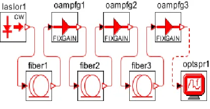
[image:2.612.330.538.579.687.2]The properties of the individual elements shown in the OPTSIM layout of Fig.1 could be set according to our requirements.
Fig. 1: Overall Layout in OPTSIM
International Journal of Emerging Technology and Advanced Engineering
Website: www.ijetae.com (ISSN 2250-2459, Volume 2, Issue 1, January 2012)139
The layout is then simulated. For viewing the results, the optical Spectrum analyzer is used. After the execution, we have obtained the following results.
Optsim Results:
International Journal of Emerging Technology and Advanced Engineering
Website: www.ijetae.com (ISSN 2250-2459, Volume 2, Issue 1, January 2012)140
International Journal of Emerging Technology and Advanced Engineering
Website: www.ijetae.com (ISSN 2250-2459, Volume 2, Issue 1, January 2012)141
[image:5.612.59.277.543.695.2]III. MATLAB RESULTS
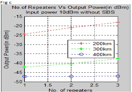
Fig. 10 : Output power Vs No. of repeaters
Fig 11: Output power Vs No. of repeaters
International Journal of Emerging Technology and Advanced Engineering
Website: www.ijetae.com (ISSN 2250-2459, Volume 2, Issue 1, January 2012)142
IV. CONCLUSION
In this paper, in order to optimize the spacing between the repeaters, we have tried to maximize the power threshold of SBS considering all the influencing factors and thereby backscattering is avoided as in ref[10]. As all the parameters are interrelated we have taken one fiber non-linearity i.e., SBS and its tradeoff with the input power, correspondingly increasing the input power to increase the Brillouin threshold. Thus results using optsim have proved that, fiber nonlinearities proves to be a major constraint in the optimization of distance between the repeaters.
Reference:
[1] F. H. Tithi and M. S. Islam,“Suppression of Stimulated Brillouin Scattering Effect using Nonlinear Phase Modulation”, 6th
International Conference on Electrical and Computer Engineering ICECE 2010, 18-20 December 2010,Dhaka, Bangladesh.
[2] Christoph Wree, Member, IEEE, Suhas Bhandare, Member, IEEE, Donald Bec- Ker, Member, IEEE Daniel Mohr, and Abhay Joshi. “Repeaterless 10.7Gb/s DPSK Transmission Over 304 km of SSMF Using a Coherent Receiver and Electronic Dispersion Compensation”.IEEE PHOTONICS TECHNOLOGY LETTERS, VOL. 20, NO. 6, MARCH 15, 2008.
[3] John C. Mauro, Srikanth Raghavan, and A. Bohuffin” Enhanced stimulated Scattering threshold through phase control of multitone phase modulation”, 2010 Society of Photo-Optical Instrumentation Engineers. Oct. 26, 2010.
[4] John Park, Student Member, IEEE, Aly F. Elrefaie, Senior Member, IEEE, and Kam Y. Lau, Fellow,IEEE” 1550-nm Transmission of Digitally Modulated 28-GHz Subcarriers Over 77 km of Nondispersion Shifted Fiber” IEEE PHOTONICS TECHNOLOGY LETTERS, VOL9, NO. 2, FEBRUARY 1997.
[5] Akihide Sano, Tomoyoshi Klituoku, Muxihito Tonzizuwu, Kuzuo Hagimoto, Kenji Suto, Koichi Wukitu , and Kuzutoshi Kuto” Automatic dispersion equalization by monitoring extracte clock power level in a 40-Gbit/s, 200-km transmission line” 22nd Eurspean Conference on Optical Communication- ECOC'96
[6] H. Suzuki, N. Takachio, Member, IEEE, O. Ishida, Member, IEEE, and M. Koga, Member, IEEE,” Power Excursion Suppression in Cascades of Optical Amplifiers with Automatic Maximum Level Control” IEEE PHOTONICS TECHNOLOGY LETTERS, VOL. 11, NO.8, AUGUST 1999
[7] R. Giles, Member, IEEE, and Emmanuel Desurvire, Member, IEEE” Propagation of Signal and Noise in Concatenated
Erbium-Doped Fiber Optical Amplifiers” JOURNAL OFLIGHTWAVE TECHNOL LOGY, VOL. 9. NO. 2 FEBRUARY1991.
[8] Antonio Mecozzi, Member, IEEE” On the Optimization of the Gain Distribution of Transmission Lines with Unequal Amplifier Spacing” IEEE PHOTONICS TECHNOLOGY LETTERS, VOL. 10, NO. 7, JULY 1998.
[9] A. Carena, V. Curri, R. Gaudino, P. Poggiolini, Member, IEEE, and S. Benedetto,Fellow, IEEE” New Analytical Results on Fiber Parametric Gain and Its Effects on ASE Noise” IEEE PHOTONICS TECHNOLOGY LETTERS, VOL. 9, NO. 4, APRIL 1997.
[10] Huilian Ma, Zuyuan He, Member, IEEE, OSA, and Kazuo Hotate, Fellow, IEEE” Reduction of Backscattering Induced Noise By Carrier Suppression in Waveguide-Type Optical Ring Resonator
Gyro”, JOURNAL OF LIGHTWAVE TECHNOLOGY, VOL 29, NO. 1, JANUARY 1, 2011
[11] Berthold Wedding, Bernd Franz, and Bernhard Junginger, Member, IEEE” lO-Gb/s Optical Transmission up to 253 km Via Standard Single-Mode Fiber Using the Method of Dispersion-Supported Transmi sion”, JOURNAL OF LIGHTWAVE TECHNOLOGY, VOL. 12 NO. 1O, OCTOBER 1994
[12] T.Sabapathi, S, Sundaravadivelu, and P.Saravanakumar, “Capacity optimization in DWDM Optical Communication System”, International Journal on Information and Communication Technologies, Vol. 2, No. 1-2, pp. 123- 126,January – June 2009.
[13] T. Sabapathi and S.Sundaravadivelu,“Analysis of Bottlenecks in DWDM Fiber Optic Communication System”, in OPTIK, International Journal for Light and Electron Optics, ISSN 0030- 4026, Vol. 122. Issue No. 16, pp. 1453-1457, 2011.
[14] T. Sabapathi, S. Sundaravadivelu and A.Vairamuthu “Analysis of Optical Modulation Formats for DWDM system”,Intnternational Journal of Information and Communication Technologies(IJICT), Vol. 4, No. 1-2, pp. 5-10, January – June 2011.