AUTOMATIC RESIDUAL CURRENT DEVICES
AHMAD KHAIRUDDIN BONARI
A project report submitted in partial fulfillment of the
requirement for the award of the degree
Master of Electrical Engineering
Faculty of Electrical and Electronic Engineering
University Tun Hussein OnnMalaysia
v
ABSTRACT
vi
ABSTRAK
TABLE OF CONTENTS
TITLE
i
DECLARATION
ii
DEDICATION
iii
ACKNOWLEDGEMENT
iv
ABCTRACT
v
ABSTRAK
vi
TABLE OF CONTENT
vii
LIST OF TABLES
x
LIST OF FIGURES
xi
LIST OF ABBREVIATIONS
xii
LIST OF APPENDIXS
xiv
CHAPTER 1 INTRODUCTION
1
1.1
Project background
1
1.2
Problem statement
3
1.3
Objective
4
1.4
Scopes of project
4
1.5
Report outline
4
CHAPTER 2
LITERATURE REVIEW
6
2.1
Introduction
6
2.2
Residual Current Devices (RCD)
6
2.3
RCD features
7
2.5
Operation of RCD trip situation
11
2.5.1 Permanent failure or permanent damage
11
2.5.2 Temporary failure or temporary damage
11
2.6
Electrical faults
12
2.6.1 Over-current fault
12
2.6.2 Short-circuit fault
12
2.6.3 Lightning fault
13
2.7
Literature review of previous report
14
2.7.1 Automated electrical protection system for
domestic application
14
2.7.2 Development of earth leakage circuit
breaker with an auto re-closer
15
2.7.3 Automatic earth leakage circuit
breaker with backup supply
16
2.7.4 Automatic RCD integrated with arduino
17
2.8
Conclusion for previous report
18
CHAPTER 3 METHODOLOGY
19
3.1
Introduction
19
3.1.1 Phase 1: Project planning
20
3.1.2 Phase 2: Circuit diagram
21
3.1.3 Phase 3: Software development
22
3.1.4 Phase 4: Hardware design
22
3.1.5 Phase 5: Testing
22
3.1.6 Phase 6: Maintenance
22
3.2
Prototype design
23
3.3
Overall system
24
3.4
Software development
25
3.5.1 Block diagram description
26
3.5
System operation
27
3.6
Circuit stage
29
3.6.2 LCD circuit
30
3.6.3 Relay driver circuit
31
3.6.4 Current sensor
31
3.7
Proteus software
32
3.8
MPLAB software
33
3.9
SketchUp software
34
3.10 Microcontroller (PIC 16F877A)
35
3.11 Current sensor
36
3.12 LCD display
37
3.13 Relay
37
CHAPTER 4 RESULT AND ANALYSIS
39
4.1
Result of automatic residual current devices
39
4.2
Result of programming for ARCD
41
4.3
Result Stability, durability and efficiency testing
43
4.4
Analysis
44
4.5
Analysis of time sequence
44
4.6
Analysis of current sensor detection
44
4.7
Analysis during normal and fault condition
45
4.8
Calculation percentage between theories
with the actual voltage
46
4.9
RCD test using relay test unit
48
CHAPTER 5 CONCLUSION AND RECOMMENDATION
51
5.1
Conclusion
51
5.2
Future recommendation
52
REFFERENCES
53
LIST OF TABLES
4.1
ARCD Sequences
43
4.2
Stability, durability and efficiency testing
44
4.3
Time sequences
45
4.4
Measuring voltage and current using differences equipment
48
LIST OF FIGURES
1.1
Short circuit
1
2.1
Home RCD/RCCB with Housing
8
2.2
The System inside RCD
8
2.3
Residual current devices
9
2.4
Residual current devices design schematic
10
2.5
Operation of the ZCT
11
2.6
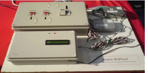
Prototype of automatic electrical protection system
for domestic application
14
2.7
Prototype of ARCD with backup supply
16
2.8
Prototype of automatic RCD integrated with arduino
18
3.1
Project planning
20
3.2
Phase planning
21
3.3
Prototype sequence event
23
3.4
Internal Prototype
24
3.5
Flowchart of Overall System
25
3.6
System block diagram
26
3.7
Flowchart of system operation
28
3.8
Overall circuit of RCD
29
3.9
Voltage regulator circuit
30
3.11 Relay Driver
31
3.12 Current sensor circuit
32
3.13 Proteus Interface
33
3.14 MP Lab interface
34
3.15 Main Application windows of SketchUp
34
3.16 Microcontroller overview
35
3.17 Current sensor
36
3.18 JHD 162A (16x2) structures
37
3.19 Relay
38
4.1
ARCD model
40
4.2
Control circuit
41
4.3
Program sequence
42
4.4
Current sensor sensitivity
44
4.5
Differences of voltage normal and fault without load
45
4.6
Measuring voltage and current using differences equipment
46
4.7
Test RCD at current 40mA (No trip)
48
4.8
Test RCD at current 77mA (ELCB trip)
48
LIST OF ABBREVIATION
PIC
Programmable Integrated Circuit
ELCB
Earth Leakage Circuit Breaker
ARCD
Automatic Residual Current devices
AEPSDA
Automated Electrical Protection System for Domestic
Application
RCD
Residential Current Device
GFCI
Ground fault Circuit Interrupted
vRCD
Voltage Residual Current devices
iRCD
Current Residual Current devices
ZCT
Zero Current Transformer
LIST OF APPENDIX
Appendix A
55
Appendix B
58
CHAPTER 1
INTRODUCTION
1.1
Project background
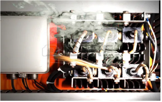
[image:12.612.198.460.522.687.2]In Malaysia, from years 2005 until 2011, there are 405 accidents due electrical fault
event, and 191 people are died due to the accidents [1]. Therefore, instead of giving
awareness on electrical safety and hazard to the public, a proper protection device
also need to be considered as part of safety. Although single phase system has its
own safety protection (i.e. earth conductor), but this is not hundred percent reliable
all the time [2]. Figure 1.1 show short circuits occur inside the resident electrical
wiring and it cause permanent fault.
Every year, many people are injured in electrical accidents at home. Not
everyone knows that many of these injuries could be prevent by having Residual
Current Devices (RCD) protection installed in the house’s consumer unit. RCD
protection can save lives by protecting ours live and ours family from fatal electric
shocks, and can also provide some protection against fire. RCDs switch off the
electricity in a friction of a second if you get an electrical shock. Having a modern
consumer unit fitted with RCDs give us the best protection because they usually
cover all the wiring, sockets and appliances at home [3].
This project is focused on the design and build of Automatic Residual
Current Devices using PIC 16F877A where the system can auto switch the RCCB.
Nowadays RCD is manually controller by mechanical switch and have a limited
function which are cannot distinguished and notify either permanent or temporary
fault accorded. The problem come when there is no resident at house whenever the
fault or tripping occurred. The electrical equipment power is disconnected because
some trouble for the resident [3]. Power reliability and continuity is very important
and critical to a domestic building. There are electrical equipment and appliances
which need to be continuously turned ON even when the occupants leave the
building for a period of time such as security system, refrigerator and aquarium
ventilation system [3]. When the system in the resident is disconnected cause some
trouble for the owner to manage the equipment. By using the auto reclose RCD the
system urgently back to normal whenever the fault and the tripping occurred and also
would rescue or save life of the equipment, especially the electronic good for
example refrigerator, television and laptop in the critical condition [3]. This may
seem unimportant, but if this problem solved it can save equipment life also give
easier to user. The new ARCD function does not limited the auto switching, but it
also can differentiate and display the type of fault so that the user is aware the
situation[3].
The system has three conditions where normal, check and fault condition.
Normal condition is no fault, check condition is system try to check either temporary
or permanent fault and fault condition is permanent fault it need user fixed the
problem before manually switch ON the RCCB.
1.2
Problem statement
Residual current devices are one type of electrical equipment that used as a
protection device. The main purpose of this type of equipment is to cut off the power
when the problem occurred. The main problem is, if the error occurred and there is
no human that can switch on back the device due to many reasons [3].
The device used is mechanical switch that must be activated manually, after
RCD is being tripped it stay off until the user push it back to the ON condition
although the problem that occurred is temporary fault and occurred in one
millisecond. So, it not works as automatic device that can operate automatically [3].
Normal circuit breaker requires someone to push the reset button after
tripping occurs. When tripping occurs and there is no one at home, it affects electric
and electronic devices that require continuous electric supply. For example, if
security system can’t function properly due to temporary short circuit, consumers
pay a lot of money to build security system for ensure their home safe from any
accident or problem. The system breakdown if electrical fault occur either temporary
or permanent fault. If temporary fault cause the breakdown, this problem should
solve by use Automatic RCD. The fire, anti thief and civilian’s camera system can
operate as usually if power continuity devices apply in domestic electrical wiring
system.
1.3
Objective
For this project, there have three objectives for ensure that this project can give
benefit to users. The objectives of this project are:
i.
To investigate the characterization of an Automatic Residual Current Devices
with automatically trigger during permanents and temporary fault.
ii.
To develop the Automatic Residual Current Devices controlled by
microcontroller during permanent or temporary fault due to surge current.
iii.
To validate effectiveness of Automatic Residual Current Devices compare to old
Residual Current Devices during permanent or temporary fault.
1.4
Scope of project
Three scopes are outlined to ensure that this project was always on the right track.
The scope for this project is:
i.
The circuit used microcontroller is programmed using C language to control relay
driver for turn ON the Automatic residual current devices during permanent fault
or temporary fault.
ii.
The range for voltage that cover for this project is limited only 220 to 240V that
be coming from suppliers for residential.
iii.
This project focused on 40A current sensor sensitivity in RCD against leakage
current at normal condition, permanent fault, and temporary fault.
1.5
Report outline
target to resolve the problem. Scopes of project are the limitation of problem to
solve.
Chapter II explains about the literature review. The explanation is about the
protective device that used in the power system, types of RCD and the types of fault
current occurred. The function of RCD was also explained in detail.
Chapter III discuss about the methodology that are used to solve the problem.
The explanations are including the types of component used to solve the problem,
their function in detail and the operation of the component to achieve the research
objective.
Chapter IV explains about the development of automatic earth circuit breaker.
The explanations include the operation of the circuit design, the function of servo
motor and how the PIC controls the entire device operation. This chapter also discuss
about the result obtain and the problem that encountered during the making of
device.
CHAPTER 2
LITERATURE REVIEW
2.1
Introduction
This section discusses some literature reviews on the previous technologies that have
been development by other researchers. The previous technology has been
summarizing to give better understanding. This section also commends on people’s
works, such as the advantage or disadvantages of the technology used, the possibility
for the technology to be further expended or developed and the improvement that
may be carried out in order to enhance the performance of the ARCD. In this section
also discuss the concept of RCD, RCCB, and theory of system protection.
2.2
Residual current devices (RCD)
RCD is designed to prevent electrocution by detecting the leakage current,
which can be far smaller (typically 5-30 mill amperes) than the currents needed to
operate conventional circuit breakers or fuses (several amperes). RCD (Residential
Current Device) are intended to operate within 25-40 milliseconds, before electric
shock can drive the heart into ventricular fibrillation, the most common cause of
death through electric shock [1].
In the United States, the National Electrical Code requires GFCI (Ground
Fault circuit Interrupter) devices intended to protect people to interrupt the circuit if
the leakage current exceeds a range of 4-6 mA of current (the trip setting is typically
5 mA) within 25 milliseconds. RCD devices which protect equipment (not people)
are allowed to trip as high as 30 mA of current. In Europe, the commonly used RCD
have trip currents of 10-300 mA[2].
Residual current devices are complementary to over-current detection.
Residual current detection cannot provide protection for overload or short-circuit
currents. RCD with trip currents as high as 500 mA are sometimes deployed in
environments (such as computing centers) where a lower threshold would carry an
unacceptable risk of accidental trips. These high-current RCD serve more as an
additional fire-safety protection than as an effective protection against the risks of
electrical shocks [2].
For many years, the voltage operated ELCB and the differential current
operated ELCB were both referred to as ELCB because it was a simpler name to
remember. However, the use of a common name for two different devices gave rise
to considerable confusion in the electrical industry. If the wrong type was used on an
installation, the level of protection given could be substantially less than that
intended. To remove this confusion, IEC decided to apply the term Residual Current
Device (RCD) to differential current operated ELCB. Residual current refers to any
current over and above the load current [2].
2.3
RCD features
mechanical switch and the black box [5]. Figure 2.2 shows the whole RCD
component inside the housing, the most important thing is the system is the good
insulator must be used for live and neutral cable, it is to avoid from RCD self
fault[5].
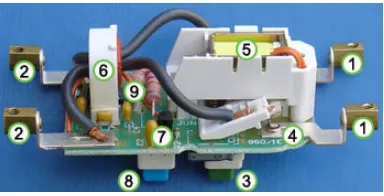
[image:19.612.311.503.164.262.2]The incoming supply and the neutral conductors are connected to the
terminals at (1) and the outgoing load conductors are connected to the terminals at
(2). The earth conductor (not shown) is connected through from supply to load
uninterrupted. When the reset button (3) is pressed the contacts ((4) and hidden
behind (5)) close, allowing current to pass. The solenoid (5) keeps the contacts
closed when the reset button is released. The sense coil (6) is a differential current
transformer which surrounds (but is not electrically connected to) the live and neutral
conductors. In normal operation, all the current down the live conductor returns up
the neutral conductor. The currents in the two conductors are therefore equal and
opposite and cancel each other out. Any fault to earth causes some of the current to
take a different return path which means there is an imbalance (difference) in the
current in the two conductors (single phase case), or, more generally, a nonzero sum
of currents from among various conductors (for example, three phase conductors and
one neutral conductor). This difference causes a current in the sense coil (6) which is
picked up by the sense circuitry (7). The sense circuitry then removes power from the
solenoid (5) and the contacts (4) are forced apart by a spring, cutting off the
electricity supply to the appliance. The device is designed so that the current is
interrupted in milliseconds, greatly reducing the chances of a dangerous electric
shock being received. The test button (8) allows the correct operation of the device to
be verified by passing a small current through the orange test wire (9). This simulates
Figure 2.1: Home
RCD/RCCB with housing
[image:19.612.148.505.164.316.2]a fault by creating an imbalance in the sense coil. If the RCD does not trip when this
button is pressed then the device must be replaced [5].
2.4
RCD design
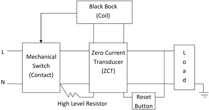
[image:20.612.167.501.363.539.2]Figure 2.3 shows the design of RCD, the design consists of Mechanical Switch, ZCT,
Black Box, High Level Resistor and the Reset Button. Mechanical switch is a contact
of black box, the function of this component is to trigger and cut off the power with
cut off the life and neutral line altogether. The function of high level resistor or test
resistor is to test whether RCD is operational or not by providing a short circuit
within internal RCD life and neutral. By providing a new current path during test
condition (assuming Kirchhoff current law), current flow through life wire is divided.
Figure 2.3: Residual current devices
The current in the neutral is less than the current in the life wire when the
reset button is pushed. The function of the reset button is to re-set back the device to
the initial condition and also as a point to detect whether the device still in good
condition or damage/expired. The function of this black box is to induced magnetic
and then de-energize the magnetic coil in the black box [6].
Figure 2.4 show the Residual current devices schematic. The function of ZCT
is to detect the unbalance current from life and neutral or life with ground. The
!
"
!
# $ % " & #
"
(
[image:21.612.195.463.158.328.2]tripping of an RCD is depending on the sensitivity of the ZCT. For resident, usually
RCD that is being used is a 0.1 A that means if there is any unbalance current
100mA, the ZCT induced current and then de-energizes the magnetic coil in black
box, so that the mechanical switch can be disconnected [7].
Figure 2.4: Residual current devices design schematic
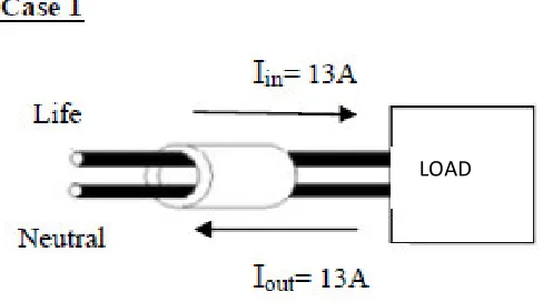
Figure 2.5 shows the operation of the ZCT. Operation of ZCT is same like the
Clamp Meter that is used to detect current in a line. In case 1, when the current flow
through life and neutral line is same, there is no unbalance current detect in the ZCT
thus there is no induced current produced by the ZCT. In case 2, when there is
unbalance current between life’s and neutral, ZCT produced an induced current and
then it send to the signal to the magnetic coil resulting in tripping of the RCD [7].
Iin = I
out, there is no induced current produced by the ZCT
" '
#t %
) * + %
, * % - !
[image:21.612.218.462.519.655.2])-Iin Iout, thus there is induced current produced by the ZCT.
[image:22.612.226.451.77.215.2]The higher difference in input and output current, result in more
induced current produced.
Figure 2.5 Operation of the ZCT
2.5
Operation of RCD trip situation
There are two types of fault normally detected by RCD, which are permanent fault
and temporary fault:
i.
Permanent failure or permanent damage.
ii.
Temporary failure or temporary damage.
2.5.1 Permanent failure or permanent damage
It usually trip when have any leakage current in circuit to earth or ground. For
permanent failure, the damaged must to repair first or remove the damage from
current before automatically trigger back RCD. If the damage not to repair or remove
the damage from circuit, it trip again when the RCD become automatically trigger.
If this happen many times, it damage the RCD. For example is electrical, electronic
device or short circuit [6].
)-2.5.2 Temporary failure or temporary damage
It can automatically trigger RCD without to repairs first or remove the damage from
supply circuit. If usually lightning and over loading occurs in resident or industrial, it
can give more problems to user to automatically trigger by itself. For example is
lightning [6].
2.6
Electrical faults
A fault is any abnormal situation in an electrical system in which the electrical
current may or may not flow through the intended parts. Equipment failure also
attributable to some defect in the circuit, example is loose connection, insulation
failure or short circuit etc. The type of faults in a distribution network that is detected
by an RCD is [7]:
i.
Over-current fault
ii.
Short-circuit fault
iii.
Lightning fault
2.6.1 Over-current fault
which a circuit or a fuse is designed to carry, the fuse or wire may melt or damage
the other elements of the circuit [8].
2.6.2 Short-circuit fault
A short circuit in an electrical circuit is one that allows a current to travel a long a
different path from the one originally intended. The electrical opposite of a short
circuit is an “open circuit”, which is an infinite resistance between two nodes. It is an
abnormal low-resistance connection between two nodes of an electrical circuit that
are meant to be at different voltages. This result in an excessive electric current
(over-current) and potentially causes circuit damage, overheating, fire or explosion.
Although usually the result of a fault, there are cases where short circuits are caused
intentionally, for example, for the purpose of voltage-sensing crowbar circuit
protectors. In circuit analysis, the term short circuit is used by analogy to design at a
zero-impedance connection between two nodes. This forces the two nodes to be at
the same voltage. In an ideal short circuit, this means there is no resistance and no
voltage drop a cross the short, in simple circuit analysis, wires are considered to be
shorts. In real circuits, the result is a connection of nearly zero impedance, and
almost no resistance [8].
2.6.3 Lightning fault
flows along the ionized path. One of the temporary faults is cause by direst lightning
phenomena. Where example of permanent fault is fault on electrical equipment [8].
2.7
Literature review of previous report
Previous studies conducted over the last report intended to provide knowledge about
the method used and the results of the findings. It also serves as a guideline in the
income of this project to ensure that all objectives of the project can be accomplished
properly.
2.7.1 Automated electrical protection system for domestic application
[image:25.612.213.467.555.681.2]The automatic system is designed for domestic electrical system to auto-reset RCD
and auto-detection if any permanent fault occurred. The system operation is divided
into two parts: power recovery and fault location detection. Power recovery is a
process of turning back the power ON when electric power encounters unexpected
shut down for a period of time due to tripping or faults. A quick power recovery is
important for equipment or electrical appliances which require continuous power
supply such as refrigerator, water pump for aquarium, alarm system and others.
When fault is occur, RCD trip and break the electrical supply from mains to all
feeders (electrical appliances or loads). The prototype shows in Figure 2.6
An automatic system is needed to switch ON RCD so the power supply can
be restored. However, if the fault is permanent, the RCD not able to turn ON.
Therefore, to overcome the problem, a system with ability of detecting fault location
need to be developed. Once fault detected and isolated, RCD be switched ON and
supply is restored. Domestic electrical fault would normally occur at individual
circuit, either switches or sockets. Electrical fault may occur due to current leakage
or over current condition, such as overload or high level short circuit, and may occur
at any point in the domestic electric system. Fault location detection may facilitate
the process of power recovery to recover from unexpected power outage. To isolate
faulty circuit from main line, the location of the fault must first be identified [2]. The
advantages of this system is RCD turn ON back when temporary fault occurs and it
know which load had a problem went permanent fault occurs. The disadvantages are
the system using GSM to send information to user where it gives many problems to
user when we need pay to GSM provided.
2.7.2 Development of earth leakage circuit breaker with an auto re-closer
Focus in improving RCD using mechanical switch into electrical switch. There are
two type detection by RCD its temporary fault and permanent fault. ZCT sense the
fault and send the signal to RCD to set the power to the load. After 10 second the
RCD connected back the power load, after that if the RCD remain connected with the
load that mean the fault is temporary. Meanwhile if he RCD is connected back to the
load and it still detect any fault, it be reclose back. The cycle repeat three times, if
fault still detect, the RCD isolate the power from the load and it display the
permanent fault.
In this project PIC microcontroller be used to control and operate the Solid
State Relay SSR, thus replacing the current mechanical switch [1]. This project used
PIC18F4550 where this microcontroller has some disadvantages compare to
PIC16F877A. PIC16F877A have more space memory and IC leg that mean user easy
to add feature recommendation without add differences IC.
2.7.3 Automatic earth leakage circuit breaker with backup supply
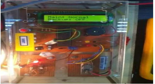
[image:27.612.203.453.546.682.2]Automatic Earth Leakage Circuit Breaker (ARCD) with the backup supply that can
auto switching and always on with temporary power supply. There are two types of
fault normally detected by RCD, which are permanent fault and temporary fault.
Uninterrupted power supply (UPS) or generator system is a device which provided
emergency power and line regulation to connect equipment by supplying power from
separate source when utility power is not available. The main focus for this project is
to prevent all the critical equipment in the house system from being breakdown. .
The concept is that if faulty occurred, after 10 second, the RCD automatically switch
back to normal condition. At the time when that RCD trip, UPS or generator use
temporary backup supply. By using the UPS or generator system back up the system
urgently whenever the fault and tripping occur and also save life equipment. This
system also can differences and display the type of fault so that the user is aware the
situation either permanent fault or temporary fault. The prototype is shown in Figure
2.7.
If there is no fault detected after the RCD is on, the LCD display main RCD in
fault condition and backup RCD is ON. The RCD stay connected until next fault
occurred and the counter reset. After PIC counter reach 2, the RCD tripped as to
isolated connection of load with power line. LCD display backup RCD in fault
condition. In this project the PIC microcontroller has been chosen as a control and
the Power Relay is selected as switching device [3]. This project have disadvantages
where only use backup supply and not turn ON the RCD that mean the system can
handle only two times of lightning strike, if third lighting strike occur the system go
to permanent fault. User need reset the system before third lightning strike and if user
not reset the system that mean the system cannot operate normally it give losses to
users.
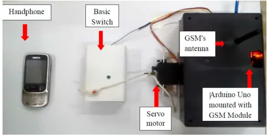
2.7.4 Automatic RCD integrated with arduino
The project is to make automatic circuit breaker which recloses the circuit after
tripping occur. This automatic RCD must be able to push back the reset button to its
usual position within short period of time. This invention be an alternative for the
manually reclose RCD. The purpose of this project is to build devices that can ON
the RCD back automatically. Earth Leakage Circuit Breaker (RCD) is a mechanical
device for making and breaking a circuit both under normal conditions and under
abnormal conditions. When tripping occurs, RCD need to turn ON manually. The
problem arises when there is no one nearby the area when tripping occurs to turn it
ON back. This system can send alert to the house’s owner if tripping occurs more
than three times consecutively, meaning this massage indicate that there is permanent
failure occur along the circuit and the house owner have to take a look at the
condition.
[image:29.612.198.464.173.307.2]
(30)interval per trip, the ICOMSAT GSM send message to house owner's hand phone to
alert them about the fault that occur in the system. The disadvantages are the system
using gsm to send information to user where it gives many problems to user when we
need pay to gsm provided [4]. The prototype is shown in Figure 2.8.
Figure 2.8: Prototype of automatic RCD integrated with arduino
2.8
Conclusion
CHAPTER 3
METHODOLOGY
3.1
Introduction
In order to complete this project, development of the method and step is an important
to make sure this project was successful without any problems. This chapter is based
on the following major parts discussed in the following section. It deals with the
actual design and construction of the project. Methodology is the process to find the
suitable project, make the researching and study all of the project information,
choose the suitable method for design this project, planning the time and selecting
the equipment such as material is needed and computer software program.
(
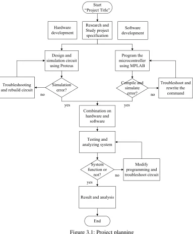
3.1.1 Phase 1: Project planning
[image:31.612.124.507.256.720.2]Phase 1 formulating the problem, determining the objective and defines the
project scope. This phase focus on investigating and establishing an idea to perform
the design selected. Usually in this stage, it is important to collect all the data related
to the idea from any source for information. Basically several problems that maybe
obtain in this project are listed in this phase to due overcome any constraint in this
project development.
Figure 3.1: Project planning
!
" #
#
$
"
# %
$ #
% %
&
"
'
#
( %
)
[image:32.612.279.370.117.465.2]
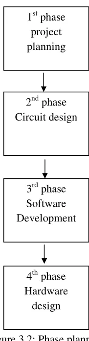
(33)This chapter divide into 4 phase that involved are very important in
conjunction to make this ARCD function base on the Figure 3.2.
Figure 3.2: Phase planning
3.1.2 Phase 2: Circuit diagram
Phase 2 literature review is based on material collected from previous publish project
material. Furthermore, hardware and software specification and requirement can be
determined. Software chosen for this project is MPLAB and PROTEUS. The suitable
methods for the hardware development and program interfacing are observed.
1
stphase
project
planning
2
ndphase
Circuit design
3
rdphase
Software
Development
4
thphase
Hardware
3.1.3 Phase 3: Software development
This phase is focus on designing circuit and developing program for the system.
Flow Chart methodology applied in this project. As companion, flowchart, schematic
and circuit diagram is design during this phase.
3.1.4 Phase 4: Hardware design
After development of a circuit and program, next phase is integrating and combine
both parts. In this phase troubleshoot and modifications are needed if any errors
occur during the testing phase. Any errors occur is improved by modifying the
program or troubleshooting the circuit. In this stage hardware for prototype designed.
3.1.5 Phase 5: Testing
Testing phase are divided into two level first level is unit step, where the system is
tested part by part. Second level is integration test where the complete combine
system between hardware and software part is examined. The analysis and finding
are important to ensure success and effectiveness of the project.
3.1.6 Phase 6: Maintenance
3.2 Prototype design
[image:34.612.139.512.264.577.2]Figure 3.3 shown prototype of ARCD where this system can detect earth fault,
lightning strike and short circuit. This system completely with the current sensor
which is used for detect current at the line and RCCB to detect unbalance current.
This system control by microcontroller PIC16F877A is used to control all the ARCD
system automatically according current sensor. This system have test button is used
to test system for temporary or permanent fault.
Figure 3.3: Prototype sequence event
According Figure 3.4 internal prototype it show inside distribution box and
control box. RCCB and MCB is important component inside ARCD circuit it is used
to detect unbalance current, lighting strike and short circuit. RCCB tie to the geared
motor use rope for trigger RCCB back to the normal condition and it is controlled by
microcontroller. MCB is compulsory in standard wiring circuit of Suruhanjaya
Lighting Strike
Short Circuit
[image:35.612.137.515.143.388.2]
(36)Tenaga Malaysia. reset button is used to reset all system, LCD display is used to
display condition either in normal, check or fault condition, LED indicator is used to
indicate condition and consumers easy to see the condition of circuit.
Figure 3.4: Internal prototype
3.3
Overall system
Figure 3.5 shows the overall step to complete this project. This project, is divided by
two parts which are hardware development and software development. For the
hardware development, the PIC circuit is used for control the relay driver and display
the condition of trip. For the software development, there are two software used, it is
MPLAB and PROTEUS. MPLAB use for create the coding program for PIC. The
PROTEUS has been chosen in the circuit design to develop the hardware for this
project.
RCCB
MCB
Reset button
LCD display
53
REFERENCES
[1]
Mohd Tarmizi Bin Rahim “Development Of Earth Leakage Current With An Auto
Reclosed Unit” University Malaysia Pahang: (2009).
[2]
M.N Syarizal, “Automated Electrical Protection System for Domestic
Application”
in Proceedings International Power Engineering and Optimization
Conference
(PEOCO ‘13), pp. 23-28, 2013.
[3]
M.A MOHD Anuar “Automatic Earth Circuit Breaker With Backup Supply”
University Tun Hussein Onn Malaysia: (2013).
[4]
MD.H Hajar “Automatic ELCB Integrated With Arduino” University Teknologi
Malaysia: (2014).
[5]
Robert L. Boylestad, Louis Nashelsky,
Electronic Device And Circuit
Theory
ninth edition, pearson education international (639-643) (778-782).
[6]
Mohd Azraie bin Suarin “Automatic Tester Devive for Earth Leakage Circuit”.
Universiti Malaysia Pahang: (2008).
[7]
Wan Rusmaezame bin Wan Mahmood “Development of Earth Leakage Circuit
Breaker Using solenoid” .Universiti Teknologi Malaysia: (2008)
[8]
Suruhanjaya Tenaga.
Prohibition on The Use Of Voltage Operand Earth Leakage
Circuit Breaker
(ELCB). Tuesday, 13 March 2007.
[9]
“Elektron”,
Electrical Shock and Fire Hazard Protection Conquering The
Limitations.
September 1993.
[10]
Alvarion.
Lightning Protection
. (1-21) October 2005.
54