Reliable Relay Node Placement in Large Scale Dense &
Non-Uniform Wireless Sensor Network
Vivekanand Jha
Department of Computer Science Indira Gandhi Institute of technologyGGSIPU
Neeharika Taneja
Department of Computer Science Indira Gandhi Institute of technologyGGSIPU
Harshpreet Kaur
Department of Computer Science Indira Gandhi Institute of technologyGGSIPU
ABSTRACT
A Wireless sensor network(WSN) is composed of a large number of sensor nodes, which are densely deployed ei-ther inside the phenomenon or very close to it. Unlike traditional networks, a WSN has its own design and re-source constraints. As sensor nodes operate on limited battery power, energy usage is a very important concern in a WSN; and there has been significant research focus that revolves around harvesting and minimizing energy. In the proposed work , assuming the WSN to be large scale and non uniform an algorithm is proposed which includes- selection of cluster head from dominating set node,creation of clusters with one and only one cluster head and Relay node deployment in clusters and between cluster heads. In this algorithm, approach of cluster-ing and relay node placement are combined for efficient utilization of energy, thus maximizing network lifetime.
General Terms:
Clustering, Energy Efficiency, Relay Nodes
Keywords:
Wireless Sensor Networks, Dominating Set, Cluster Head, Relay Nodes
1. INTRODUCTION
A wireless sensor network is composed of hundreds or even thou-sands of sensor nodes which use wireless links to perform dis-tributed sensing tasks. Each sensor node includes a sensing mod-ule, a computing modmod-ule, memory and a wireless communication module with a very limited communication range. Wireless sen-sor network has received intensive research attentions due to its enormous application potential in battlefield surveillance, environ-mental monitoring, biomedical observation and other fields[1] . The three basic requirements for designing efficient wireless sensor net-works are scalability, fault-tolerance and energy efficiency. A sen-sor network, comprising of a number of sensen-sor nodes, is usually required to cover a large geographic area. New sensor nodes may be added to the network and existing sensor nodes may become inoperative at any time. This large scale and frequently changing network requires scalable protocols and algorithms. Factors, such
as energy depletion, harsh environmental conditions, and/or mali-cious attacks may result in node failures in a wireless sensor net-work. Therefore, survivability of sensor networks is a critical de-sign goal. Moreover, energy is one of the most precious resource in wireless sensor networks. Sensor nodes are normally powered by batteries and can only last for a fairly short period of time if operated at high transmission power levels.
2. BACKGROUND WORK
2.1 Dominating Set
A Dominating Set, DS is defined as a set of nodes in the network such that all nodes in the network which are not in the DS are adja-cent to at least one node in the DS. When the graph induced by a DS is connected, then it is called CDS. For any arbitrary network, the problem of computing a CDS of minimum cardinality is an NP-complete problem [41]. The efficiency of multi-cast or broadcast routing can be improved through the use of a DS as backbone. A DS- backbone eliminates redundant broadcasts and saves power. One such approach is
2.1.1 Distributed Single-Phase algorithm for constructing a connected dominating set( DSP-CDS). DSP-CDS is a distributed algorithm. It is designed to achieve three goals. First, it generates a Connected Dominating Set(CDS) fast in a single phase. Secondly, it generates the CDS of competitively small size compared with other distributed algorithms. Thirdly, it efficiently maintains the CDS under network topology changes. In the DSP-CDS algorithm, each node in the network has a unique ID, called nid. A node can be in one of the three states: white, gray, and black. A dominator is in the black state.
A node adjacent to a dominator, if it is not a dominator itself, is in the gray state. All the other nodes (neither black nor gray) are white. A piece is a connected sub-network during the CDS con-struction. Connected black nodes and their gray neighbours form one piece. A white node itself is a piece. A piece has a unique ID, called pid, known to all nodes in the piece. A piece has a spe-cial node called master. The master of a trivial piece is the white node itself, and the master of a non-trivial piece is one of the black nodes. The piece master decides the pid of the piece. The strength of a node indicates the ability of the node to connect with differ-ent pieces. The execution of each node is divided into rounds. In each round, a node exchanges status messages with its neighbours, updates its strength, and decides if it should become a dominator. If the new strength is 0, the node will not change its state (white, gray, or black). If the new strength is greater than 0, the node de-cides its new state based on its current status (including the value of strength) and the local knowledge about its neighbours. A node adjacent to a dominator, if it is not a dominator itself, is in the gray state. All the other nodes (neither black nor gray) are white. A piece is connected sub-network during the CDS construction. Connected black nodes and their gray neighbours form one piece. A white node itself is a piece. A piece has a unique ID, called pid, known to all nodes in the piece. A piece has a special node called master.-The master of a trivial piece is the white node itself, and the master of a non-trivial piece is one of the black nodes. The piece mas-ter decides the pid of the piece. The strength of a node indicates the ability of the node to connect with different pieces. The exe-cution of each node is divided into rounds. In each round, a node exchanges status messages with its neighbours, updates its strength, and decides if it should become a dominator. If the new strength is 0, the node will not change its state (white, gray, or black). If the new strength is greater than 0, the node decides its new state based on its current status (including the value of strength) and the local knowledge about its neighbours.
In the DSP-CDS implementation, the strength of a node i is com-puted using the following rules:
(1) Rule-1: If node i is black, its strength is 0;
(2) Rule-2: If node i is gray or white, its strength is the sum of the points contributed by its neighbours;
(3) Rule-3: A black or white neighbour contributes 2 points, and a gray neighbour contributes 1 point, with the following excep-tions:
—A neighbour with the same pid as node i contributes 0 point to the strength of node i;
—Among the neighbours sharing the same pid only the one that can contribute the greatest points contributes to the strength of node i.
2.2 Clustering
In most wireless sensor network (WSN) applications nowadays the entire network must have the ability to operate unattended in harsh environments in which pure human access and monitoring cannot be easily scheduled or effeciently managed or its even not feasi-ble at all [46]. Sensors are energy constrained and their batteries usually cannot be recharged. Neighboring sensor nodes generally have the data of similar events because they collect events within a specifc area. If each node individually transmits the collected data to the sink node, a lot of energy will be wasted to transmit similar data to the sink node. The sensor nodes are organized into a num-ber of clusters in order to avoid such energy wastes. Clusterbased architectures improve the resource allocation and reduce the energy consumption, thus prolong the network lifetime as much as possi-ble [30]. Each cluster is monitored and controlled by a node, called Cluster-Head (CH). These cluster heads communicate directly with the base station (BS). Other nodes send the data, sensed from the environment to these CHs. CHs first aggregate the data from the multiple sensor nodes, and then
nally send it directly to the BS . The one algorithm used is LEACH
2.2.1 Low Energy Adaptive Clustering Hierarchy . LEACH[34] is perhaps the first cluster based routing proto-col for WSN , which use a stochastic model for cluster head selection, and has motivated the design of many protocols. Its an hierarchical, probabilistic, distributed, one-hop protocol, with main objectives (a) to improve the lifetime of WSNs by trying to evenly distribute the energy consumption among all the nodes of the network and (b) to reduce the energy consumption in the network nodes (by performing data aggregation and thus reducing the number of communication messages). It forms clusters based on the received signal strength and also uses the CH nodes as routers to the BS. All the data processing such as data fusion and aggregation are local to the cluster. LEACH forms clusters by using a distributed algorithm, where nodes make autonomous decisions without any centralized control. All nodes have a chance to become CHs to balance the energy spent per round by each sensor node. Initially a node decides to be a CH with a probability p and broadcasts its decision. Specifically, after its election, each CH broadcasts an advertisement message to the other nodes and each one of the other (non-CH) nodes determines a cluster to belong to, by choosing the CH that can be reached using the least communication energy (based on the signal strength of each CH message). The role of being a CH is rotated periodically among the nodes of the cluster to balance the load. The rotation is performed by getting each node to choose a random number T between 0 and 1. A node becomes a CH for the current rotation round if the number is less than the following threshold:
T(i) = p 1−p∗rmod1
else T(i) =0 where
p is the desired percentage of CH nodes in the sensor population
r is the current round number
G is the set of nodes that have not been CHs in the last 1/p rounds .
The clusters are formed dynamically in each round and the time to perform the rounds are also selected randomly. Generally, LEACH can provide a quite uniform load distribution in one-hop sensor net-works. Moreover, it provides a good balancing of energy consump-tion by random rotaconsump-tion of CHs. Furthermore, the localized coordi-nation scheme used in LEACH provides better scalability for clus-ter formation, whereas the betclus-ter load balancing enhances the net-work lifetime. However, despite the generally good performance, LEACH has also some clear drawbacks. Because the decision on CH election and rotation is probabilistic, there is still a good chance that a node with very low energy gets selected as a CH. Due to the same reason, it is possible that the elected CHs will be concentrated in one part of the network (good CHs distribution cannot be guaran-teed) and some nodes will not have any CH in their range. Also, the CHs are assumed to have a long communication range so that the data can reach the BS directly. This is not always a realistic assump-tion because the CHs are usually regular sensors and the BS is of-ten not directly reachable to all nodes. Moreover, LEACH forms in general one-hop intracluster and intercluster topology where each node should transmit directly to the CHs and thereafter to the BS, thus normally it cannot be used effectively on networks deployed in large regions.
2.3 Relay Nodes
In general, the relay node placement problem has been studied un-der two perspectives, namely the routing structure and the connec-tivity requirements. The study based on the routing structure may be further classified into either single tiered or two-tiered [6], [7], [9], [11]. The study based on connectivity can be classified into ei-ther connected or survivable [4], [7], [15], [14]. In single-tiered re-lay node placement, the SNs may also forward packets. In twotiered relay node placement, the SNs transmit their sensed data to an RN or a BS, but do not forward packets for other nodes. In connected relay node placement, the placement of RNs ensures connectivity between the SNs and the BSs. In survivable relay node placement, the placement of RNs ensures biconnectivity between the SNs and the BSs.
Two optimization problems for relay node placement in large scale sensor networks[2], one is called Connected Relay Node Single Cover (CRNSC) problem and another is 2-Connected Relay Node Double Cover (2CRNDC) problem. Two polynomial time approxi-mation algorithms are presented to solve the CRNSC problem. We show that the size of the CRNSC given by the first approximation algorithm is bounded by eight times that of the optimal solution and the second one achieves a performance ratio of 4.5. Moreover, we propose two approximation algorithms to solve the 2CRNDC problem and we also prove that performance ratios associated with them are 6 and 4.5, respectively.
In a large scale WSN where nodes are non-uniformly distributed we aim to place relay nodes such that relay node is reachable by at least 1 sensor node. We assume the field to have set S, as sensor node such that they have a transmission range of r. The sensor nodes are mobile and change topology after some time. Being non-uniformly placed there might be dense areas where more than 20 sensor nodes may be present in 1 metric cube. However, no interference of data
while aggregation at relay node is assumed. Relay nodes are used only for receiving and transmitting data bidirectional between sen-sor nodes and relay nodes or relay nodes and relay nodes or sink and relay nodes. The transmission radius of relay node is r such that r is not same as R.
To do this we place Relay nodes hierarchically. Clusters are formed for set S, such that no sensor node is shared by any two clusters and each sensor node in set S is present in at least and at most 1 cluster. Cluster head is chosen based on dominating set nodes from set, S. Dominating set is formed using the following parameters:
—Residual Energy of Nodes
—Neighbours of Node
Relay node is placed inside clusters as well as outside. Certain con-straints such that, a sensor node must have at least 1 relay node to transmit data to it. Per sensor node 1 fault of relay node is tolerated. This provides fault tolerance in relay node placement. Additional relay nodes are placed around cluster head and in between cluster head. The cluster head of each cluster know distance between itself and all the cluster heads in the field and also the distance from the sink. We will also place additional relay nodes around dense areas.
3. PROPOSED WORK
In a large scale WSN where nodes are non-uniformly distributed we aim to place relay nodes such that relay node is reachable by at least 1 sensor node. We assume the field to have set S, as sensor node such that they have a transmission range of r. The sensor nodes are mobile and change topology after some time. Being non-uniformly placed there might be dense areas where more than 20 sensor nodes may be present in 1 metric cube. However, no interference of data while aggregation at relay node is assumed. Relay nodes are used only for receiving and transmitting data bidirectional between sen-sor nodes and relay nodes or relay nodes and relay nodes or sink and relay nodes. The transmission radius of relay node is r such that r is not same as R.
To do this we place Relay nodes hierarchically. Clusters are formed for set S, such that no sensor node is shared by any two clusters and each sensor node in set S is present in at least and at most 1 cluster. Cluster head is chosen based on dominating set nodes from set, S. Dominating set is formed using the following parameters:
—Residual Energy of Nodes
—Neighbours of Node
Relay node is placed inside clusters as well as outside. Certain con-straints such that, a sensor node must have at least 1 relay node to transmit data to it. Per sensor node 1 fault of relay node is tolerated. This provides fault tolerance in relay node placement. Additional relay nodes are placed around cluster head and in between cluster head. The cluster head of each cluster know distance between it-self and all the cluster heads in the field and also the distance from the sink. We will also place additional relay nodes around dense ar-eas. In this section we propose the algorithms we use to place relay nodes . We first create a dominating set, followed by clustering and finally relay node placement.
3.1 Design Parameters
3.1.1 Node Degree. Each node computes its degree. The degree of a node y is the total number of nodes within the transmission range of v.
Dg= X
uV,u6=v
Duv
where Duv is the distance between node u and v.
3.1.2 Transmission range. The transmission range, Tr, of a node is a factor that determines the quality of the clusterhead. This pa-rameter is more relevant in the case of heterogeneous networks.
3.1.3 Transmission range. The transmission range, Tr, of a node is a factor that determines the quality of the clusterhead. This pa-rameter is more relevant in the case of heterogeneous networks.
3.1.4 Fault Tolerance. Some sensor nodes may fail or be blocked due to lack of power, have physical damage or environmental inter-ference. The failure of sensor nodes should not affect the overall task of the sensor network. This is the reliability or fault tolerance issue. Fault tolerance is the ability to sustain sensor network func-tionalities without any interruption due to sensor node failures .
R(t) =exp(−µt)
3.2 Proposed Solution
3.2.1 Construction of Dominating Set. The algorithm used for constructing dominating set is the modified version of DSP-CDS as described in section 2.3
Algorithm 1: DSP-DS
(1) compute strength ()
// Compute the strength of a node based on the local knowledge about neighbors
compute strength{ if (no neighbor)
// strength for an isolated node return InvalidStrength; new strength = 0;
// Compute the strength using information of neighbors if
the node is not black if (state != black) {
// Count points of black or white nodes in the first round for each black/white neighbor i
{
new strength += 2 + TR/MD; }
// Count points of gray nodes in the second round for each gray neighbor node i
{
new strength += 1 + TR/MD; }
}
return new strength; }
Where TR= transmission radius
MD= Maximum distance of that node with any other node
(2) Each node execution program
define InvalidStrength = 1; state = white;
// Initial strength value strength = InvalidStrength; reset timer t1 = T1; reset timer t2 = T2; upon expiration of t1 {
// Compute a new strength s = compute strength();
broadcast STATUS(nid, state, s); reset timer t1 = T1;
}
upon expiration of t2{
if (state == black — — strength == 0) return;
// Compute a new strength strength = compute strength();
// Get the maximum strength among neighbors (s, n) = get max neighbor();
if ((strength, nid) ¿ (s, n)) state = black;
reset timer t2 = T2; }
upon receiving a STATUS message S{ save neighbour(S.nid) = ( S.state, S.strength);
reset timer neighbourTimer(sender.nid) = Neighbour-Exp;
if ((S.state == black) and ( state == white)){ state=gray;
} {
upon expiration of neighbor Timer(nid){ delete neighbor(nid);
3.2.2 Choose Cluster head. Four factors are being considered while electing cluster head
(1) Percentage of cluster heads required (2) Residual Energy of a node
(3) Fault tolerance (4) Degree of node
Algorithm 2: Cluster Head Nomination
(1) A node n chooses a random number between 0 and 1. (2) If the number is less than a threshold T(n), the node
be-comes a cluster head for the current round. (3) The threshhold is set as t(n), where
T(n) = p 1−p∗(rmod1
p)
∗Eres
Ein
∗Kopt∗R(t)∗D(n)
Kopt=
√
N
√ 2π ∗
Ef s
Emp
∗ M
dBS2
R(t) =exp(−µt)
(4) where
µ
=failure rate of sensor node
(5) D(n)= probability of a node to have maximum degree (6) Announce CH status
(7) CH sends packets to its 1 hop neighbors informing them about its nomination as a cluster head.
(8) Wait for Join request message
(9) CH waits for the join request message from its neighbor-hood sensor nodes.
3.2.3 Cluster Formation . Following is the algorithm of the clus-ter formation :
Algorithm 3 : Cluster Formation
A sensor node receives the JOIN request messages from more than 1 cluster head.
The decision of which cluster head should it join is dependent on four
factors:-(1) Residual energy of a cluster head (2) Distance between CH and node (3) Distance between CH and base station (4) RSSI- Received Signal Strength Indicator
A node sends the join message to the selected CH
3.2.4 Relay Node Placement. It involves 2 algorithms. These can be described as :
4.2.4.1 WITHIN CLUSTER: Ensure connected relay node single cover(CRNC)
Given a set of locations of non-uniformly distributed sensor nodes S, the communication range of sensor nodes ,SN Range, and the communication range of relay nodes RN Range, find the minimum number of relay nodes and their corresponding locations, so that each sensor node is covered by at least one relay node, and that the set of relay nodes is connected. It Ensures each SN is covered by at least 1 RN node . At least 1 RN should be present within TR of SN . This RN should be reachable to and from CH. This ensures connected SN-RN-CH graph
(1) For each Cluster
(2) Input all SN in cluster in List, L (3) While L!=NULL
(4) {
(5) Select sensor node with largest distance from its CH (6) If(RN in transmission radius of sensor node ie SNRange) (7) {
(8) Ensure that RN can reach CH (9) }
(10) Else (11) {
(12) Place RN between CH and SN such that RN is at dis-tance SNRange from SN. The direction should be the line of sight of SN and CH. Ensure that RN placed can reach CH.
(13) Place more RN on line of sight of current RN and CH (14) }
(15) Remove SN from List, L (16) }
—1 Cluster-wise run this algorithm to place Relay nodes in-side cluster
—2 Insert all SN of cluster in a list so that we can verify that each SN can reach at least 1 RN.
—Repeat until all the sensor node have been treated. In the loop either the SN will have a relay node around it or it wont.
—4&5. Select SN which is farthest from CH. This way Relay nodes placed will be minimum in number because the re-lay nodes will be placed in collinear with SN and CH and towards the CH at distance SNRange from SN.
—6. Check if RN is found within the SNRange for selected SN in while loop
—7,8,9: if RN is present ensure that this RN can send trans-missions to CH. That is, it is connected to CH via other relay nodes
—10,11,12: if RN is not found within transmission range of selected SN, place a relay node such that:
(2) It is on same line in which co-ordinates of SN and CH lie
(3) It is placed in between CH and SN
—13 . If distance between RN and CH is more than RNRange place more RN between them such that
(1) It is at distance RNRange from newly placed RN (2) It is on same line in which co-ordinates of RN and CH
lie
(3) It is placed in between CH and RN. —14. Remove SN from list
4.2.4.2 WITHIN CLUSTER: Ensure single node, double cover problem.
Given a set of locations of uniformly distributed sensor nodes S, the communication range of sensor nodes SNRange, and the commu-nication range of relay nodes RNRange, find the minimum number of relay nodes and their corresponding locations so that each sensor node is covered by at least two relay nodes, and that the network of relay nodes is 2-connected.
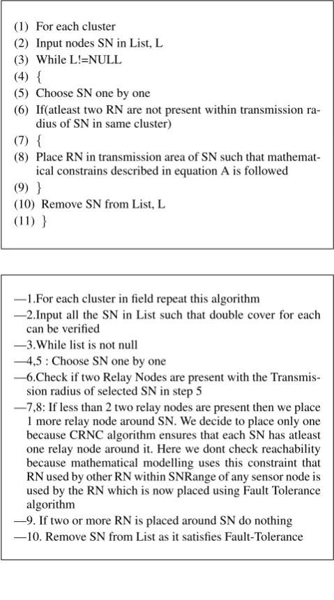
(1) For each cluster
(2) Input nodes SN in List, L (3) While L!=NULL (4) {
(5) Choose SN one by one
(6) If(atleast two RN are not present within transmission ra-dius of SN in same cluster)
(7) {
(8) Place RN in transmission area of SN such that mathemat-ical constrains described in equation A is followed (9) }
(10) Remove SN from List, L (11) }
—1.For each cluster in field repeat this algorithm
—2.Input all the SN in List such that double cover for each can be verified
—3.While list is not null —4,5 : Choose SN one by one
—6.Check if two Relay Nodes are present with the Transmis-sion radius of selected SN in step 5
—7,8: If less than 2 two relay nodes are present then we place 1 more relay node around SN. We decide to place only one because CRNC algorithm ensures that each SN has atleast one relay node around it. Here we dont check reachability because mathematical modelling uses this constraint that RN used by other RN within SNRange of any sensor node is used by the RN which is now placed using Fault Tolerance algorithm
—9. If two or more RN is placed around SN do nothing —10. Remove SN from List as it satisfies Fault-Tolerance
4. SIMULATION
MATLAB is used for simulating the algorithm. MATLAB is a high-performance language for technical computing. It integrates com-putation, visualization, and programming in an easy-to-use envi-ronment where problems and solutions are expressed in familiar mathematical notation.
4.1 Performance Analysis
4.1.1 Simulation Parameters —Field size (MM) : 100m100m
—Location of BS(Base Station):75m ¡ dBS ¡ 100m —Number of nodes, N : 100 nodes
—Cluster-head (CH) probability : 0.1 —Initial Energy of sensor node : 0.02J —ETX and ERX (Eelec) : 50 nJ/bit —Free space ( fs ): 10 pJ/bit/m2
—Multipath fading (mp) : 0.0013 pJ/bit/m4 —The energy for aggregation (EDA): 5 nJ/bit/signal
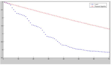
[image:6.595.53.291.67.192.2]4.1.2 RESIDUAL ENERGY COMPARISON GRAPHS. We simu-lated the Leach algorithm and our proposed algorithm in MATLAB and ploted various graphs comparing the Residue Energy when a large wireless network of nodes is Clustered using the LEACH al-gorithm and the proposed Clustering alal-gorithm. Following graph shows the comparison of Residual energies when 50 nodes have been used in our WSN.
Fig. 1. Comparison of residual energies when 50 nodes have been
[image:6.595.53.293.290.720.2]used in our WSN.In the above scenario the Residual energy has in-creased from 0.6246 Joules in case of LEACH algorithm to 0.6600 Joules in case of the PROPOSED algorithm.
Figure 1 shows the Comparison of residual energies in case of LEACH algorithm and when the proposed algorithm was used.The number of nodes used is 50.T he Residual energy has increased from 0.6246 Joules in case of LEACH algorithm to 0.6600 Joules in case of the PROPOSED algorithm.
[image:6.595.324.550.370.525.2]Fig. 2. Comparison of residual energies when 100 nodes have been used in our WSN.In the above scenario the Residual energy has in-creased from 1.2266 Joules in case of LEACH algorithm to 1.3492 Joules in case of the PROPOSED algorithm.
5. RESULTS AND CONCLUSION
The simulation of leach algorithm and the proposed algorithm has yield the following results in terms of Energy consumption and Network lifetime.
We have proposed a fine strategy for relay node placement in large scale, dense, non uniform sensor network. Five different cases have been discussed and their appropriate algorithms are proposed.The proposed algorithm suggested in 3.2.4 ensures connected relay node single cover situation within clusters. Single node, double cover problem is being handled efficiently by the algorithm de-scribed in section 3.2.4 (2). Placement of relay nodes is based on formed clusters.
In order to form the clusters, dominating set is used as a backbone in WSN. The algorithm used for constructed dominating set is a modified version of DSP-CDS[33]. Among the nodes belonging to the dominating set, cluster heads are chosen based on proposed algorithm 2. Finally, proposed Algorithm 3 is used during the for-mation of clusters.
Our approach has considered the combination of various factors that are relevant for efficient utilisation of power and thus minimis-ing energy consumption in WSN. The algorithms are simulated on MATLAB R2007b and the results proved that the proposed algo-rithm increases the network lifetime and conserves the energy by 13.456 % as compared against the LEACH algorithm.
6. REFERENCES
[1] I.F. Akyildiz, W. Su, Y. Sankarasubramaniam, E. Cayirci, Wireless sensor networks: a survey, Computer Networks Jour-nal 38 (2002) 393- 422.
[2] Jian Tang*, Bin Hao, Arunabha Sen, Relay node placement in large scale wireless sensor networks, Computer Communica-tions 29 (2006) 490 501
[3] Y.T. Hou, Y. Shi, H.D. Sherali and S.F. Midkiff; Prolonging sensor network lifetime with energy provisioning and relay node placement; Secon05; pp. 295 304.
[4] J. Bredin, E. Demaine, M. Hajiaghayi and D. Rus; Deploying sensor networks with guaranteed capacity and fault tolerance; Mobihoc05; pp. 309- 319.
[5] X. Cheng, D.Z. Du, L. Wang and B. Xu; Relay sensor place-ment in wireless sensor networks; ACM/Springer WINET07;
[6] A. Efrat, Sandor P. Fekete, P. Gaddehosur, J. Mitchell, V. Polishchuk and J. Suomela; Improved Approximation Algo-rithms for Relay Placement; ESA08; pp.356 367.
[7] B. Hao, J. Tang and G. Xue; Fault-tolerant relay node place-ment in wireless sensor networks: formulation and approxi-mation; HPSR04; pp. 246-250.
[8] H. Liu, P.J. Wan and X.H. Jia; Fault-tolerant relay node place-ment in wireless sensor networks; LNCS; Vol. 3595(2005), pp. 230 239.
[9] E. Lloyd and G. Xue; Relay node placement in wireless sensor networks; IEEE Transactions on Computers; Vol. 56(2007), pp. 134138.
[10] S. Misra, S. Hong, G. Xue and J. Tang; Constrained relay node placement in wireless sensor networks to meet connec-tivity and survivability requirements; Infocom08.
[11] ] J. Pan, Y.T. Hou, L. Cai, Y. Shi, S.X. Shen; Topology control for wireless sensor networks; Mobicom03, pp. 286299. [12] A. Srinivas, G. Zussman, and E. Modiano; Mobile
back-bone networks Construction and maintenance, Mobihoc06, pp. 166177.
[13] K. Xu, H. Hassanein, G. Takahara and Q. Wang; Relay node deployment strategies in heterogeneous wireless sensor net-works: multiple-hop communication case; Secon05, pp. 575-585.
[14] W. Zhang, G. Xue, and S. Misra; Fault-tolerant relay node placement in wireless sensor networks: problems and algo-rithms; Infocom07; pp.16491657.
[15] A. Kashyap, S. Khuller and M. Shayman; Relay placement for higher order connectivity in wireless sensor networks; In-focom06.
[16] D. Estrin, R. Govindan, J. Heidemann, S. Kumar, Next cen-tury challenges: scalable coordination in sensor networks, ACM MobiCom99, Washingtion, USA, 1999, pp. 263270. [17] G. Hoblos, M. Staroswiecki, A. Aitouche, Optimal design of
fault tolerant sensor networks, IEEE International Conference on Control Applications, Anchorage, AK, September 2000, pp. 467472.
[18] D. Nadig, S.S. Iyengar, A new architecture for distributed sen-sor integration, Proceedings of IEEE Southeastcon93, Char-lotte, NC, April 1993.
[19] C. Shen, C. Srisathapornphat, C. Jaikaeo, Sensor informa-tion networking architecture and applicainforma-tions, IEEE Personal Communications, August 2001, pp. 5259.
[20] E. Shih, S. Cho, N. Ickes, R. Min, A. Sinha, A. Wang, A. Chandrakasan, Physical layer driven protocol and algorithm design for energy-efficient wireless sensor networks, Pro-ceedings of ACM MobiCom01, Rome, Italy, July 2001, pp. 272286 .
[21] S. Cho, A. Chandrakasan, Energy-efficient protocols for low duty cycle wireless microsensor, Proceedings of the 33rd An-nual Hawaii International Conference on System Sciences, Maui, HI Vol. 2 (2000), p. 10.
[22] N. Bulusu, D. Estrin, L. Girod, J. Heidemann, Scalable coor-dination for wireless sensor networks: self-configuring local-ization systems, International Symposium on Communication Theory and Applications (ISCTA 2001), Ambleside, UK, July 2001.
sensor networks, Proceedings of the ACM Mobi- Com00, Boston, MA, 2000, pp. 5667.
[24] J.M. Kahn, R.H. Katz, K.S.J. Pister, Next century challenges: mobile networking for smart dust, Proceedings of the ACM MobiCom99, Washington, USA, 1999, pp. 271278.
[25] G.J. Pottie, W.J. Kaiser, Wireless integrated network sensors, Communications of the ACM 43 (5) (2000) 551 558. [26] A. Porret, T. Melly, C.C. Enz, E.A. Vittoz, A low-power
low-voltage transceiver architecture suitable for wireless dis-tributed sensors network, IEEE International Symposium on Circuits and Systems00, Geneva, Vol. 1, 2000, pp. 5659. [27] Weiyi Zhang, Guoliang Xue and Satyajayant Misra,
Fault-Tolerant Relay Node Placement in Wireless Sensor Networks: Problems and Algorithms, 2007 IEEE
[28] Y. Thomas Hou, Senior Member, IEEE, Yi Shi, Student Mem-ber, IEEE,Hanif D. Sherali, and Scott F. Midkiff, Senior Member, IEEE, On Energy Provisioning and Relay Node Placement for Wireless Sensor Networks, IEEE TRANS-ACTIONS ON WIRELESS COMMUNICATIONS, VOL. 4, NO. 5, SEPTEMBER 2005
[29] K. Lu G. Liu R. Mao Y. Feng, Relay node placement based on balancing power consumption in wireless sensor networks, The Institution of Engineering and Technology 2011 [30] Hai Liu, Peng-Jun Wan, and Xiaohua Jia, Fault-Tolerant
Re-lay Node Placement in Wireless Sensor Networks, Springer-Verlag Berlin Heidelberg 2005
[31] Santhosh Pandey ,Shaoqiang Dong ,Prathima Agrawal ,Kr-ishna M. Sivalingam, On Performance of Node Placement Approaches for Hierarchical Heterogeneous Sensor Net-works, Springer Science + Business Media, LLC 2008 [32] Dejun Yang, Satyajayant Misra, Xi Fang, Guoliang Xue, and
Junshan Zhang, Two-Tiered Constrained Relay Node Place-ment in Wireless Sensor Networks: Efficient Approxima-tions,2010 IEEE
[33] R. Agrawal, and R. Srikant, Fast Algorithms for Mining As-sociation Rules, Proceedings of the 20th VLDB, pp. 487499, 1994.
[34] S.K. Chong, S. Krishnaswamy, S.W. Loke, and Mohamed Gaber, Using Association Rules for Energy Conservation in Wireless Sensor Networks, Proceedings of the 23rd ACM Symposium on Applied Computing, Brazil, 2008.
[35] A. Deshpande, C. Guestrin, and S.R. Madden, Using Proba-bilistic Models for Data Management in Acquisitional Envi-ronments, Proceedings of the 2005 CIDR Conference, 2005. [36] W. Heinzelman, A. Chandrakasan, and H. Balakrishnan. An
Application-Specific Protocol Architecture for Wireless Mi-crosensor Networks, IEEE Transactions on Wireless Commu-nications, Vol. 1, pp. 600-670, 2002.
[37] W. Hu, V.N. Tran, N. Bulusu, C.T. Chou, S. Jha, and A. Tay-lor. The Design and Evaluation of a Hybrid Sensor Network for Canetoad Monitoring, Proceedings of Information Pro-cessing in Sensor Networks (IPSN 2005/SPOTS 2005), Los Angeles, 2005.
[38] P. Levis, N. Lee, M. Welsh, and D. Culler, TOSSIM: Accu-rate and Scalable Simulation of Entire TinyOS Applications, SenSys 2003, 2003.
[39] K.K. Loo, I. Tong, B. Kao, and D. Cheung, Online Algo-rithms for Mining Inter-Stream Associations From Large Sen-sor Networks, PAKDD, pp. 143-149, 2005.
[40] R. Marin-Perianu, M. Marin-Perianu, and P. Havinga, Move-mentbased Group Awareness with Wireless Sensor Networks, Proceedings of Pervasive 2007, 2007.
[41] V.S. Anitha, M.P. Sebastian, A Connected Dominating Set-based Weighted Clustering Algorithm for Wireless Sensor Networks, IEEE 2010
[42] L. Jia, R. Rajaraman, and T. Suel, An efficient distributed al-gorithm for constructing small dominating sets, Distrib. Com-put., vol. 15, no. 4, pp. 193205, 2002.
[43] Julia Albath, Mayur Thakur, Sanjay Madria, Energy Con-strained Dominating Set for Clustering in Wireless Sensor Networks, 24th IEEE International Conference on Advanced Information Networking and Applications, 2-5, 2010 [44] Bolian Yin, Hongchi Shi, Yi Shang , An efficient algorithm
for constructing a connected dominating set in mobile ad hoc networks, J. Parallel Distributed Computing 71(2011) 27-39 [45] Do-hyun Nam, hong-ki min, An Efficient Ad-Hoc Routing
Using aHybrid Clustering Method in a Wireless Sensor Net-work, Wirelessand Mobile Computing, Networking and Com-munications, pp. 60-60, Oct 2007.
[46] A.A. Abbasi and M. Younis, A survey on clustering algo-rithms for wireless sensor networks, Computer Communica-tions, 30, 28262841, 2007.
[47] Wendi B Heinzelman, Anantha P. Chandrashekhan, Hari Bal-akrishan, An application specific protocol architecture for wireless Senesor Network, IEEE 2002
[48] Ma Chaw Mon Thein, Thandar Thein , An energy efficient Cluster Head Selection for Wireless Sensor network, 2010 Int. Conf. on Intelligent systems, Modelling and simulation. [49] 0. Younis, et. al., HEED: A Hybrid, Energy-Efficient,
Dis-tributed Clustering Approach for AdHoc Sensor Networks, IEEE Transactions on Mobile Computing, 3(4):660-669, 2004.
[50] S. Lindsey, et. al. ,PEG ASIS: Power-Efficient Gathering in Sensor Information Systems, IEEE Aerospace Conference Proceedings, Vol. 3, 9-16 gust, pp. 102-114, 2002.
[51] Shujuan Jin, Keqiu Li, LBCS: A Load Balanced Clustering Scheme in Wireless Sensor Networks, 2009 Third Interna-tional Conference on Multimedia and Ubiquitous Engineer-ing, IEEE