Design of M-Commerce based Model for e-Enablement
of Land Record Information System
Kanwalvir Singh
Associate Prof.(CSE & IT Dept.) B.B.S.B.Engg.College, Fatehgarh Sahib (Punjab) India
Himanshu Aggarwal
Professor (Computer Deptt.) U.C.O.E, Punjabi University,
Patiala (Punjab) India
ABSTRACT
The latest trends related with enhancement of the mobile devices and mobile technologies have lead to the need to model such unique & innovative applications. This is necessary in order to have wide adoption and impact of such devices and their applications in today’s fast paced life of a common man. The process of modeling the proposed mobile application with Unified Modeling language (UML) has been described with the application of use case diagrams, sequence diagrams, component diagrams and deployment diagrams in this work. The goal of this paper is to illustrate the model-based approach for the M-commerce model application developed for e-Enablement of land record information system. The art of analyzing, specifying, visualizing and documenting the object-oriented system has been very well described with the modelling process of unified modelling language. The application model developed in this case, mobileLoan app showcases the various aspects of UML and its components. The approach is demonstrated using UML diagrams developed for testing a mobile application having graphical user interface (GUI).
Keywords
UML, mobileLoanApp, e-Governance, Punjab, M-commerce, Information system.
1.
INTRODUCTION
M-commerce applications have brought a sea change in the technological advancements all around the globe. The design concerned with such software system can be made effective only with the application of CASE tools for the software development life cycle process. Here, UML can really make a significant difference in the application development aspects of the real time web applications, particularly the e-Governance applications [6]. Since Unified Modeling language (UML) is used to define system classes and also describe the relationships among classes, it forms backbone for the design and construction phases of m-commerce systems development process. UML is visual, object-oriented,
describes business processes both structurally and
dynamically and helps to derive better system requirements to provide a common language for both the business analysts and developers [3]. The usability and security aspects being the important factors that influence mobile users, the
comparative framework for evaluating such mobile
applications are a must so as to lay solid foundation in their development. The extension to the UML can be used to specify an application's search ability in an efficient way with the resulting models used to generate large parts of the search ability implementation automatically [4].
2.
LITERATURE REVIEW
Various previous years’ research papers have been studied which form the basis of our work. A.B.H.Ali et al. (2012) examined UML-based design and validation of reconfigurable embedded control systems & defined a set of UML-compliant metamodels to explain the system architecture, the reconfiguration scenarios and their events. The application testing based on UML Models has been described in a real-time research project so as to showcase the improvement in the effectiveness and practicality of software testing & to address application testing in a “real world” scale (M.Vieira et al., 2006). A.Uhl, et al. (2002) presented a model-driven approach and extension to the UML to specify an application's searchability in an efficient way with the resulting models used to generate implementation automatically. I. Traore et al.(2012) illustrated Model-Driven SPE (MDSPE) approach in which annotated UML performance models can be designed for the performance analysis of distributed software systems based on the UML profile and a case study of a business system has been used for validation of the results. M.Genero(2011) in their research paper described systematic literature review (SLR) of peer-reviewed conference and journal articles published in the last 18 years till 2009 based on the quality of UML models and classified them into various types on the basis of model quality, evidence, research result, and research goal. An integrated and methodological approach for the determination and representation of context specially related to the characteristics and design of mobile commerce applications has been presented through its depiction as metadata and the presentation of extension of class diagrams of UML (P.Benou, et al., 2010). S.Balsamo, et al., 2004 also presented a comprehensive review of the field
of model-based performance prediction at software
development time so as to assess the maturity of the field and to point out further research directions. Badica, C. et al. (2005) proposed a model agent-based e-commerce system with lightweight modular mobile agent design and introduced UML formalizations of the important agents that appear in the model system as well as presentation of its complete action diagram. M.Wimmer et al. (2011) focused on the aspect-oriented design modeling by presenting a conceptual reference model and then capturing the design concepts of AOM and their interrelationships with respect to UML class diagram.
3.
CURRENT EXISTING SCENARIO –
LAND RECORDS
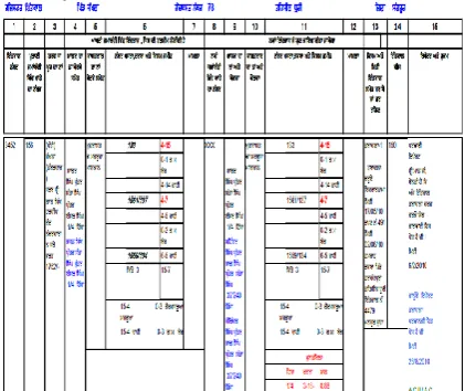
is seen as a revolutionary step so as to improve the overall depleting state of the revenue records of Punjab. The Farad Kendra’s (land information centres) have been established all over the State at the various Tehsils and sub-Tehsils level in each and every district of Punjab. These Farad Kendra’s located at various Tehsils and sub-tehsils have been connected to district headquarters-Farad Kendras, which are further connected to PLRS (Punjab land record society) headquarters. The information at various districts is thus interconnected with the central information web server maintained at PLRS. The up-to-date lands records at Farad Kendra’s are provided to the PLRS headquarter. Thus, PLRS headquarter is acting as repository of information for all the land records of the Farad Kendra’s in Punjab state. PLRS website is also used for updating all the revenue records of Punjab state. It provides online information of land records of most of the villages of Punjab after digitization of revenue information of land records. The records of few villages which are still not digitized are also going to complete within the coming months. The digitized copy of land record (Farad) taken from Farad Kendra showing the revenue record in Jamabandi register is as shown in Fig.1. Urban and semi-urban land records are also undergoing digitization for it to be further interconnected to the registry records. This will result in the online interconnection between the revenue deeds, registries with the current updated land records of the common citizens of the Punjab state.
Fig. 1: Digitized copy of land record (Farad) taken from Farad Kendra showing the revenue record in Jamabandi
register
4.
UML & APPLICATION
DEVELOPMENT
UML (Unified Modelling Language) has been accepted as de-facto standard by the Object Management Group (OMG). UML has been founded by Grady Booch, James Rumbaugh, and Ivar Jacobson. UML is the primary modeling language used to analyze, specify, and design software systems [5]. According to Grady Booch, “The UML is a language used for visualizing, constructing and documenting the artifacts of software”. UML 2.0 diagrams are used in object oriented analysis and design of the various types of software systems. The various diagrams which are part of UML 2.0 diagram subset are: Use case diagrams, Class diagrams, Activity diagrams, Sequence diagrams, Interaction diagrams, State machine diagrams, Component diagrams and Deployment diagrams, etc. The UML enables system builders to create
blueprints that capture their visions in a standard, easy to understand way and communicate them to others [8].
5.
ABOUT THE APPLICATION
The paper presents the mobile device application
(mobileLoanapp) developed for the client of the bank for the loan approval process. The bank server of the bank and land server of the revenue department are interconnected so as to share information between each other. The model device application developed is a light-weight and open-source application developed using Google Map which acts as an intermediary between the bank server and land server. The application developed forms the intercommunication between the mobile phone app, land server and the bank server.
6.
MOBILELOANAPP MODEL
The customer (client) has to personally visit the bank for the sanctions and approvals (clearance) of loan from the bank, requesting to the concerned authorities for loan approval. This has been a tedious process of first proving the authentic property records (land records) to the bank officials & then going through a lengthy, tedious process of completing the documentation. This process often has made the customer feeling harassed to complete lengthy list of formalities which are needed for getting the necessary loan approval. This innovative mobile application, mobileLoanApp will help in almost removing these traditional procedural hassles for getting the loan approval.
6.1 Components
The framework of this mobile device application consists of three components mainly:
a. mobileLoan app: Device application (app running on mobile phone).
b. Bank server: Authentication server of the bank. c. Land server: Authentication server of the revenue department.
[image:2.595.316.546.514.648.2]6.2
Connectivity Diagram
Figure 2 belowshows the Internet Connectivity view of three
way intercommunication between the mobile phone app, land server and bank server.
Fig. 2: Internet Connectivity view of mobile phone app with land server and bank server
7.
ANALYSIS OF THE MODEL – THE
WORKFLOW
The workflow of system developed is explained with following series of various UML diagrams used for the analysis of the mobile device application, mobileLoanApp.
Bank Server Land Server
Mobile
Gateway Client
Internet
7.1 Tool Used - STARUML
The tool used for analysis and design of the developed mobileLoanapp model in UML (unified modelling language) is StarUML ver.5.0. StarUML is free to download and is open source project used extensively for developing model diagrams in UML.
7.2
Designing
&
Modelling
of
Mobileloanapp
The design and modeling of mobile device application developed is analyzed using various types of diagrams as described below.
7.2.1 Use-Case Diagram – I
A use case is a description of a system’s behavior from a user’s standpoint [8]. In the Use-case diagram-I (Fig.3), three different GUI-screens form the interface. The client interacts using this interface with the mobile application for the loan approval process. Database-1 (DB-1) of bank connects with the bank server for validation of the client record (personal information data of client). Database-2(DB-2) of land server is used to retrieve land record number (LRN) and its location by the land record server. The record is passed to the Google Map application for the land number to be displayed.
Client
Apply loan (option) Enters act. & passwd
Puts LRN (request ID generated)
Google Map API land record server
land no. transacted land no. retreived
NewUseCase
Bank server
request passed
record passed
GUI-screens
DB-2-retreives LRN & location
validates LRN DB 1- client record
[image:3.595.334.531.137.433.2]record validation
Fig. 3: Use case diagram-I
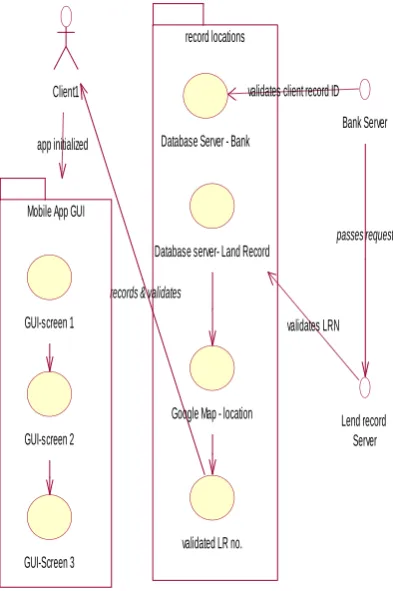
7.2.2 Use-Case Diagram – II
Use case diagrams are used to depict the context of the system to be built and the functionality provided by that system [5]. Fig.4 shows Use-case diagram-II having two interfaces, record locations and Mobile App GUI. UML Use Case Diagrams are used to represent the functionality of the application from a top-down perspective [2]. After the bank server and land record server validates client ID record and
land record number(LRN) respectively, Google Map retrieves the land location for it to be forwarded to the mobile application(mobile app). Interaction occurs between client, servers and mobile application in this use case diagram-II as shown below in Fig.4
Lend record Server Bank Server
passes request
record locations
Database Server - Bank
validates client record ID Client1
validated LR no.
records & validates
Google Map - location Database server- Land Record
GUI-screen 1
GUI-Screen 3 GUI-screen 2 Mobile App GUI
app initialized
validates LRN
Fig. 4: Use case diagram-II
7.2.3 Sequence-Diagram
The flow of sequence diagram is from left to right direction. The UML sequence diagram shows the time-based dynamics of the interaction [8]. The mobile app is initialized and loan approval process is initiated (triggered) through various GUI screens. Client-ID record is requested by the bank server, to be further retrieved from its database. The core of the interactions between system objects are clarified by the application of sequence diagrams [6]. Location and land record number (LRN) matching is done by the land record server after retrieving from its database. The interaction between the two servers happens through HTTP request. At the last, message is generated for the loan approval process completion on the mobile app.
7.2.4 Collaboration Diagram
[image:3.595.74.263.351.643.2]Client (mobile app GUI)
Bank server
database BS
LR server
database LRS
Google map API
DB searched
DB searched 1: requests record <token ID generated>
G
6: record validated
2: requests Client ID
3: Client ID <passed>
4: ID mapped to LRN
[image:4.595.63.267.91.350.2]5: Client-LRN <passed>
Fig. 5: Collaboration Diagram
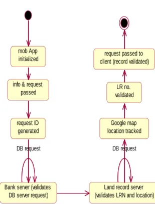
7.2.5 Activity Diagram
The activity that occurs within a use case or within an object’s behavior typically occurs in a sequence [8].The activity diagram of Fig.6 depicts the event being initialized with the opening or starting of mobile app. The info passed has request-id generated at the client mobile app end. Bank server and Land record server retrieves data after retrieving data from their respective database. LRN is validated for pledged or non-pledged land after tracking with the Google Map application. The record when validated is passed to the client for the loan approval process to complete.
mob App initialized
info & request passed
request ID generated
Bank server (validates DB server request)
request passed to client (record validated)
LR no. validated
Google map location tracked
Land record server (validates LRN and location)
DB request DB request
Fig. 6: Activity diagram
7.2.6 Deployment Diagram
The physical architecture of the whole system is exhibited by the deployment diagram. This diagram shows interconnection between the various systems and devices.
Client mobile app
Screen-GUI 1 Screen GUI-2
Screen GUI 3 app icon
Bank-Server
Farad-Centre
Front-end
database-BS
Front-end
database-LRS requests
message forwarded
requests ID-LRN record Google Map
LRN (validated)
client ID-record retreived
[image:4.595.324.532.114.358.2]LRN record retreived
Fig. 7: Deployment Diagram
Deployment Diagram of Fig.7 shows the front-end & database of the Farad centre & Bank server.The Client-id record is retrieved from the database of the bank server while LRN record is retrieved from the database of the Farad Centre.Client mobile app interface has interconnections between the three screen GUI’s. Google Map application acts as a link between the databases of the two servers. The interconnection between the various interfaces are represented by the various connectors which forms links for various requests and message forwarding links.
8. CONCLUSIONS
The Unified development process in coordination with the software development life cycle helps in the overall analysis, design, visualization and documentation of the various types of applications like mobile applications, etc. This paper proposed a software development process for modelling M-commerce mobile application developed for loan approval process involving e-Enablement of land record information system. A model-driven approach to software construction can be used to specify an application's search ability [4]. For this, UML has been employed as the modelling language to showcase the step-by-step systematic software process. The usage and application of this model process provides more simplicity and clarity to the existing system in the application development. The functional requirements of the system & system design can thus be easily captured by the object modeling concepts in terms of use case diagrams and class diagrams as in UML. Future work that can be pursued includes the application of software modelling process for the development of various types of mobile applications. This can further be applied for the software development modelling process related with the development of information systems.
9.
REFERENCES
[1] A.B.H.Ali, M.Khalgui, S.B.Ahmed, “UML-Based
[image:4.595.66.221.522.726.2]Reconfigurable Embedded Control Systems”, International Journal of System Dynamics Applications (IJSDA), Volume 1, Issue 1, 2012, 22 pages, doi: 10.4018/ijsda.2012010102
[2] M.Vieira, J.Leduc, B.Hasling, R.Subramanyan,
J.Kazmeier, “Automation of GUI Testing Using a Model-driven Approach”, AST’06, Shanghai, China, May 23, 2006, pp. 9-14.
[3] Baker, B., Business Modeling with UML: The Light at the End of the Tunnel, Copyright RationalSoftware2001, http://www.therationaledge.com/content/dec_01/m_busin essModeling_bb.html
[4] A.Uhl, H.Lichter, “A UML Variant for Modeling System
Searchability”, Proceedings of the 8th
International Conference on Object-Oriented Information Systems (OOIS'02), Springer-Verlag London, UK, 2002, ISBN: 3-540-44087-9
[5] Booch, G., Maksimchuk, R.A., Engle, M.W., Young, B.J., Conallen, J., and Houston, K.A., “Object-oriented analysis and design with applications”, Pearson
publications, 3rd Edition, 2007.
[6] K.S.Dhindsa, H.Aggarwal, “Showcasing the Modelling approach: The Unified Development for Land record Information System”, International Journal of Research in Engineering & Applied Sciences, Vol.2, Issue2, Feb.2012, pp. 453-463.
[7] P.Benou, C.Vassilakis, “The conceptual model of context for mobile commerce applications”, Electronic Commerce research Journal,Vol.10,Issue 2,June 2010,pp. 139-165, Kluwer Academic Publishers Norwell, MA, USA, doi:10.1007/s10660-010-9050-4
[8] J.Schmuller, “Teach yourself UML in 24 hours”,
Techmedia, 1st edition, 1999.
[9] I.Traore, I.Woungang, A.A.Ahmed, M.S.Obaidat,
“Software Performance Modeling using the UML: a Case Study”, Journal of Networks, Vol 7, No 1, Jan 2012, pp.4- 20, doi:10.4304/jnw.7.1.4-20
[10] Van Leeuwen, J. (ed.), “UML Software Architecture and Design Description”, Christian F.J.Lange and Michel R.V.Chaudron, Software, IEEE Volume 23, Issue 2,March-April 2006, pp. 40-46
[11] M.Wimmer, A.Schauerhuber, G.Kappel,
W.RetschitzeggerW.Schwinger, El.Kapsammer, “A
survey on UML-based aspect-oriented design modeling”, ACM Computing Surveys (CSUR) Surveys Homepage archive, Volume 43, Issue 4, October 2011, Article No. 28
[12] S.Balsamo, A.D.Marco, P.Inverardi, M.Simeoni, Model Based performance Prediction in Software Development: A Survey”, IEEE Transactions on Software Engineering, Vol. 30, No. 5, May 2004
[13] H. Gomaa and D.A. Menasce, “Design and
PerformanceModeling of Component Interconnection Patterns for Distributed Software Architectures”, ACM Proc.International Workshop Software and Performance, 2000, pp. 117-126.
[14] C.Badica, M.Ganzha, M. Paprzycki, “UML Models of
Agents in a Multi-Agent E-Commerce
System”,Proceedings of the IEEE Conference of E-Business Engineering, ICEBE 2005, 12-18 Oct. 2005, pp. 56-61.
[15] M.Genero, A.M.Fernandez-Saez, H.J.Nelson, G.Poels, And M.Piattini, “Research Review: A Systematic Literature Review on the Quality of UML Model”, Journal of Database Management (JDM), Volume 22, Issue 3, 2011, doi: 10.4018/jdm.2011070103.
[16] M.Olaniyi, D.O.Adewumi, E.A.Oluwatosin, O.T.
Arulogun, M.A.Bashorun, “Framework for Multilingual Mobile E-Voting Service Infrastructure for Democratic Governance”, Afr J. of Comp & ICTs, Vol.4, No. 3, Issue 2, 2011, pp.23-32.
[17] Y.C.Huei, L.C.Wee, K.Z.Kang., N.C.R.Jie, “Design and Implementation of Mobile and Internet Product Access
Information and Its Administration System”,