International Journal of Computer Applications (0975 – 8887) Volume 43– No.19, April 2012
On the Design of MIMO-OFDM Transceivers via
Geometric Mean Decomposition
Sridhanya. A
Department of ECE Amrita Vishwa Vidhyapeetham Coimbatore-641112
Abhiram Yarlagadda
Department of ECE Amrita Vishwa Vidhyapeetham Coimbatore-641112
Guru Prasath. D
Department of ECE Amrita Vishwa Vidhyapeetham Coimbatore-641112
Varsha Syam Sundar
Department of ECE Amrita Vishwa Vidhyapeetham Coimbatore-641112
ABSTRACT
The Geometric Mean Decomposition (GMD) based transceiver design has gained huge attention in the recent past as it provides an optimal solution in terms of BER and capacity. GMD technique has been widely adopted for the joint transceiver design as it converts the MIMO channel into identical and parallel SISO channels hence avoiding the necessity for bit loading and also achieves minimized bit error rates (BER).In this paper, we have explored the possibility of utilizing these positives of GMD for MIMO-OFDM transceiver designs, which is unavailable in the current literature. This paper considers the design of a linear Precoder and a DFE under perfect CSIT and CSIR. Using GMD, both MMSE and ZF based transceiver designs are proposed for MIMO-OFDM system. The performance of the proposed systems has been compared with other types of transceiver designs based on SVD and QR decomposition. The robustness of these proposed systems against the channel imperfections have also been analyzed.
General Terms
MIMO-OFDM transceiver design
Keywords
Decision Feedback Equalizer (DFE), Geometric Mean Decomposition (GMD), MIMO-OFDM transceiver
1.
INTRODUCTION
Orthogonal Frequency Division Multiplexing (OFDM) is an efficient multicarrier technique that converts frequency selective channels to parallel narrowband flat fading channels hence suppressing Inter Symbol Interference (ISI) to a greater extent. The orthogonal subcarriers attributes to the increased spectral efficiency [1]. It has been adopted in digital audio broadcasting (DAB), digital video broadcasting (DVB-T), the IEEE 802.11a local area network (LAN) [14] standard and the IEEE 802.16a metropolitan area network (MAN) [15] standard. On the other-hand, Multiple Input Multiple Output (MIMO) systems have proven to be the nonpareil solution for the present requisites in Wireless Communication because it provides high data rate, spectral efficiency through spatial multiplexing and high capacity. This has been evident from the adoption of MIMO system in the IEEE 802.11n (Wi-Fi), IEEE 802.16e (WiMAX) standards and in 4G, LTE, 3GPP.
MIMO systems are predominantly affected by frequency selective fading. An apparent solution for this problem is to
incorporate OFDM into the MIMO systems which helps in mitigating the inter symbol interference (ISI) [2]. Thus, MIMO-OFDM has found wide application in IEEE 802.11n WLAN and in the fourth generation mobile cellular wireless systems. These positives of MIMO-OFDM have made the transceiver design to capture attention worldwide.
Channel state information at the transmitter (CSIT) and the channel state information at the receiver (CSIR) play a significant role in the design of precoder and equalizer matrices. In this paper, we assume that the CSIT is available at the transmitter through feedback or time division duplex (TDD) scheme.
GMD based transceiver design for MIMO system has proven to be the benchmark of all the generalized triangular decomposition (GTD) [5] based transceiver designs as it converts the MIMO channels into identical and parallel SISO channels and achieves optimal capacity and minimizes bit error rate [8]. The major advantage of GMD over other decomposition techniques such as SVD is that it does not require bit allocation hence avoiding the necessity for complex decoders at the receiver. In the past and current literatures, these positives of GMD have not been utilized for MIMO-OFDM transceiver designs. So, we have extended the available GMD based MIMO transceiver design [5], [3], [11] to MIMO-OFDM transceivers.
The sections in the paper are structured as follows. In section II, an overview on channel state information and on Geometric Mean Decomposition as a special case of GTD is detailed. Section III gives an overview on the MIMO-OFDM channel. Section IV is devoted to the system model in which mathematical formulation of GMD based MIMO-OFDM transceiver designs is brought out. Finally in section V, the analysis of the systems proposed in section IV is performed and results are given graphically. Concluding remarks are given in section VI.
2.
THEORY ON GMD BASED
TRANSCEIVERS FOR MIMO OFDM
SYSTEMS
𝐻 =
011⋯
𝜇11⋮
⋮
⋮
0
0
0𝑁𝑅1⋯
0
⋯
⋮
⋮
⋮
…
𝜇𝑁𝑅1⋯
⋯
01𝑁𝑇
11𝑁𝑇⋮
⋮
⋮
⋯
0
…
⋯
𝜇1𝑁𝑇⋯
⋮
⋮
⋮
0
0𝑁𝑅𝑁𝑇⋯
0
⋮
𝜇𝑁𝑅𝑁𝑇(8)
imperfect in nature [6]. Among the available categories of CSI, known channel state information gives better system [12] performance compared to the rest as it will help to process the signal more precisely and thus helps in obtaining an optimal transceiver design. The generalized triangular decomposition (GTD) mentioned in [3], [7], results in a set of solutions for the power minimization problem with the bit allocation varying from one solution to other. The linear transceiver design based on SVD with optimal bit allocation, GMD based DFE transceiver with no bit allocation are the members of the GTD family. The QR-based system used in VBLAST is yet another member of the optimal family and is particularly well-suited when limited feedback is allowed from receiver to transmitter [3].
Using GMD, a matrix can be decomposed as [4]
𝐻 = 𝑄𝑅𝑃𝐻 (1)
where 𝑅 is a 𝐾 𝑋 𝐾 upper triangular matrix and 𝑄 is a 𝑀 𝑋 𝐾 matrix and 𝑃 is 𝑁 𝑋 𝐾 matrix where 𝑄 and 𝑃 are unitary matrices.
𝑅𝑘𝑘, the diagonal entries of the 𝑅 matrix, all are identical and
is equal to the geometric mean of the singular values of the channel matrix 𝐻.
𝑅𝑘𝑘 = ( 𝑀𝑘=0𝜎,𝑘)
1
𝑀 (2)
3.
CHANNEL MODEL FOR
MIMO-OFDM
For a general SISO OFDM system, the channel impulse response can be modeled in the form of a matrix [9] as
𝐻 =
0 1 2
0 0 1
⋮ ⋮ ⋮
⋯ ⋯ 𝜇
2 ⋯ 𝜇 −1
⋮ ⋮ ⋮
⋯𝜇 ⋯ 00 0
⋮ ⋮ ⋮
0 0 0 0 0 0 ⋯ ⋯ 𝜇
(3)
where [𝑛] denotes the filter impulse response of the multipath SISO channel with 0 ≤ 𝑛 ≤ 𝜇.Hence for SISO system, the output of the channel can be denoted by
𝑦 = 𝐻𝑥 + 𝑛 (4)
The output vector 𝑦 is of size 𝑁 𝑋 1 where, 𝑁 denotes the number of subcarriers utilized for OFDM modulation.
𝑦 = [𝑦𝑁−1 𝑦𝑁−2… … … . 𝑦0]𝑇 (5)
The input vector denoted as 𝑥 is appended with cyclic prefix of length 𝜇 hence has a size (𝑁 + 𝜇) 𝑋 1.Cyclic prefix of length 𝜇 is added to the input vector in order to combat ISI, where the 𝜇 is same as the tap size of channel impulse response.
𝑥 = [𝑥𝑁−1 𝑥𝑁−2 … … … 𝑥0 𝑥−1 𝑥−2 … … … … 𝑥−𝜇 ] (6)
The last 𝜇 symbols of the input vector 𝑥 corresponds to the cyclic prefix. It is evident that
𝑥−1= 𝑥𝑁−1, 𝑥−2= 𝑥𝑁−2, … … … , 𝑥−𝜇 = 𝑥𝑁−𝜇 (7)
A typical MIMO channel is expressed by a matrix of size 𝑁𝑅 𝑋 𝑁𝑇 with rank 𝑀, where 𝑁𝑇 corresponds to the number of transmitting antennas and 𝑁𝑅 corresponds to the number of
receiving antennas. Hence a MIMO-OFDM channel can be given by (8), where each element of a MIMO channel matrix is replaced by a SISO OFDM channel hence resulting in a channel matrix 𝐻 of size 𝑁𝑅 𝑋 (𝑁 + 𝜇)𝑁𝑇 . Hence with the
help of MIMO OFDM systems the effect of frequency selective fading is reduced by converting the wideband channelinto many narrowband channels. This channel model applies for a multipath fading MIMO channel. In the case of flat fading MIMO channels, the channel has the normal form of 𝑁𝑅 𝑋 𝑁𝑇. Hence an input vector 𝑥 to the channel will be of
size 𝑁 + 𝜇 𝑁𝑇 𝑋 1 and the output vector from the channel
will be of size 𝑁𝑁𝑅 𝑋 1 for a MIMO-OFDM channel.
4.
SYSTEM MODEL
4.1
General MIMO-OFDM Transceiver
with DFE
The model proposed in this paper assumes a low rate feedback system, which ensures the channel state information available at both the transmitter and receiver. In this paper, we consider a multipath, frequency selective fading channel. Hence, the channel model can be given by (8), here 𝐻 is the 𝑁𝑁𝑅 𝑋 (𝑁 +
𝜇)𝑁𝑇 channel matrix of rank 𝑁𝑀 whose elements are
Rayleigh iid. The system model depicted in Fig.1.
The transmitter comprises of a precoder that precodes the channel matrix in frequency domain, an interleaver and 𝑁𝑇
OFDM transmitters. The output from the transmitter side x is an (𝑁 + 𝜇)𝑁𝑇 𝑋 1 vector where 𝑁𝑇 denotes the number of transmitting antennas, 𝑁 denotes the number of subcarriers for OFDM modulation and 𝜇 denotes the channel FIR filter length which is chosen same as the cyclic prefix length.
The noise vector 𝑛 is a 𝑁𝑁𝑅 𝑋 1 zero mean circularly
symmetric complex Gaussian noise. 𝑦 is a 𝑁𝑁𝑅 𝑋 1 received
vector where 𝑁𝑅 denotes the number of receiving antennas.
The input symbols a of size 𝑀𝑁 𝑋 1 is precoded with the help of precoding matrix 𝐹 of size 𝑁𝑁𝑇 𝑋 𝑁𝑀 which is block
diagonal is obtained from the frequency domain channel matrix corresponding to 𝑁 orthogonal frequencies, resulting in a precoded vector of size 𝑁𝑁𝑇 𝑋 1. Hence these precoded
vectors must be interleaved in order to form 𝑁𝑇sets of input
symbols each of length 𝑁 which will act as input to the 𝑁𝑇 parallel IFFT blocks. Output from each of these 𝑁𝑇
parallel IFFT blocks are prepended with cyclic prefixes of length 𝜇 resulting in a transmitted vector 𝑥 of size (𝑁 + 𝜇)𝑁𝑇 𝑋 1.
𝑥𝑛𝑞 𝑡 = 𝑥𝑛,𝑙𝑒𝑗2𝜋𝛥𝑓𝑡 𝑁−1
𝑙=0
, −𝜇 ≤ 𝑡 ≤ 𝑇𝑠
𝑥𝑛𝑞 𝑡 = 𝑥𝑛𝑞 𝑡 + 𝑇𝑠 , − 𝜇 ≤ 𝑡 ≤ 0 (9)
Here 𝑥𝑛,𝑙 is the input symbol to the IFFT block and 𝑥𝑛𝑞 𝑡 is
the nth OFDM symbol, and 𝑙, 𝛥𝑓, 𝑁 and 𝑇
𝑆 denotes the
subcarrier index, the subcarrier spacing, the number of subcarriers and the OFDM symbol duration respectively. 𝜇 denotes the cyclic prefix duration which is same as the channel filter tap length.
International Journal of Computer Applications (0975 – 8887) Volume 43– No.19, April 2012
Fig.1. System Model for GMD based MIMO OFDM transceiver
end, the received vector 𝑦 of size 𝑁𝑁𝑅 𝑋 1 is grouped into 𝑁𝑅
sub vectors of length 𝑁 each. Each of these vectors is then passed parallely on to 𝑁𝑅 FFT blocks resulting in a vector of
size 𝑁𝑁𝑅 𝑋 1. This vector is then de-interleaved in order to
enable these vectors for equalization in frequency domain using the feedforward matrix 𝐺 and the feedback matrix 𝐵.
The feedforward matrix and the feedback matrix are block diagonal matrices of size 𝑁𝑀 𝑋 𝑁𝑁𝑅 and 𝑁𝑀 𝑋 𝑁𝑀. Hence
the output symbols a’ of size 𝑁𝑀 𝑋 1 are obtained using the equalization process. It is also assumed that there is no error propagation in the feedback loop.
4.2
GMD ZF based MIMO-OFDM
Transceiver
In order to obtain the precoder and equalizer matrices for GMD ZF based transceiver, the time domain MIMO-OFDM channel matrix 𝐻 is first converted to equivalent frequency domain block diagonal channel matrix 𝐻𝑓of size 𝑁𝑁𝑅 𝑋 𝑁𝑁𝑇 where each of the block diagonal entries represents the MIMO channel matrix corresponding to each of the 𝑁 subcarrier frequencies. This time domain matrix is converted to frequency domain matrix by taking 𝑁 point DFT of each 𝜇 length CIR in the MIMO OFDM matrix.
𝐻𝑓 = 𝑑𝑖𝑎𝑔 𝐻𝑓 1 , 𝐻𝑓 2 , … … , 𝐻𝑓 𝑁 (10)
In general, for a MIMO system, these matrices are obtained using the time domain channel matrix but in case of MIMO OFDM design the frequency domain channel matrices using which the precoder and equalizer matrices are designed for each of the 𝑁 subcarriers.
Using GMD we can decompose the each of the 𝑁𝑅 𝑋 𝑁𝑇
frequency domain channel matrices corresponding to each subcarrier frequency, 𝐻𝑓 𝑘 , 1 ≤ 𝑘 ≤ 𝑁 into three matrices:
𝑃(𝑘) of size 𝑁𝑇 𝑋 𝑀 , 𝑅(𝑘) of size 𝑀 𝑋 𝑀 and 𝑄(𝑘) of size
𝑀 𝑋 𝑁𝑅.
𝐻𝑓(𝑘) = 𝑄(𝑘)𝑅(𝑘)𝑃𝐻(𝑘) (11)
The matrices 𝑃(𝑘) and 𝑄(𝑘) are unitary matrices as mentioned before and 𝑅(𝑘) is an upper triangular matrix with the diagonal elements as the geometric mean of the singular values of the channel matrix 𝐻𝑓 𝑘 and it is represented using (2)
The Precoder matrix 𝐹(𝑘) is unitary in nature and is defined as
𝐹 𝑘 = 𝛼𝑃(𝑘) (12) The factor 𝛼 is selected to achieve the transmitting power constraint [5] and is given by
𝛼 = 𝑃 𝑀𝜎𝑎2
2
(13)
where = (𝑡𝑟(𝐸(𝑥 𝑘 𝑥𝐻 𝑘 ) , M is the rank of the matrix and
𝜎𝑎2 is the variance of the input symbol.
Next feedforward matrix 𝐺(𝑘) and feedback matrix 𝐵(𝑘) corresponding to all the 𝑁 frequencies are formulated as follows based on the zero forcing constraint 𝐺𝐻𝐹 − 𝐼 = 𝐵 [3] given by
𝐺(𝑘) = 𝛼−1(𝐷
𝑅(𝑘) )−1 [𝑄(𝑘)]𝐻 (14)
𝐷𝑅(𝑘) = (𝑑𝑖𝑎𝑔(𝑅(𝑘) ) (15)
𝐵 𝑘 = 𝐷𝑅(𝑘) −1𝑅 𝑘 − 𝐼𝑀 (16) Once the precoder matrix 𝐹(𝑘), feedforward matrix 𝐺(𝑘) and the feedback matrix 𝐵(𝑘), where 1 ≤ 𝑘 ≤ 𝑁, corresponding to all the frequencies have been determined, the overall precoder matrix 𝐹, feedforward matrix 𝐺 and feedback matrix 𝐵 can be determined as
𝐹 = 𝑑𝑖𝑎𝑔 𝐹 1 , 𝐹 2 , … … , 𝐹(𝑁) (17) 𝐺 = 𝑑𝑖𝑎𝑔 𝐺 1 , 𝐺 2 , … … , 𝐺(𝑁) (18) 𝐵 = 𝑑𝑖𝑎𝑔 𝐵 1 , 𝐵 2 , … … , 𝐵(𝑁) (19)
After determining the matrices for the precoder, feed forward and feedback matrices 𝐹, 𝐺 and 𝐵, the OFDM transmitter and receiver can be appended to the system. The OFDM transmitter consists of IFFT block followed by the addition of cyclic prefix. At the receiver end, FFT is performed on the OFDM symbols in order to recover the original symbols which are then equalized with the help of MMSE DFE.
The input symbols of size 𝑀𝑁 𝑋 1 are precoded and converted to symbols of size 𝑁𝑁𝑇 𝑋 1. These precoded
symbols are then interleaved and are then IFFT modulated. 𝑁 point IFFT is performed on each of the 𝑁 symbols and are prepended with cyclic prefix of length 𝜇 to form the transmitted signal 𝑥 = {𝑥1, 𝑥2, . . . , 𝑥𝑁𝑇}.
𝑥𝑙𝑞 𝑡 = 𝑥 𝑊𝑡𝑙 1 ≤ 𝑞 ≤ 𝑁𝑇 ,1 ≤ 𝑙 ≤ 𝑁 (20)
where 𝑊 is the twiddle factor matrix.
At the other end, before multiplying with 𝐺, the signal is demodulated using the FFT, de-interleaved and the result after the FFT is given by
𝑦𝑞 = 𝑛𝑇 𝑥𝑞 𝑙 𝐻 + 𝑛𝑞(𝑙)
𝑝=1 (21)
where 𝑞 is the transmitted antenna. 𝑥𝑞 𝑙 is the transmitted OFDM symbol .𝐻 is the channel matrix and 𝑛𝑞(𝑙) is the
noise added which is given by the following expression.
𝑛𝑙𝑞 𝑚 ≜ 1
𝑁 𝑛
𝑞 𝑚
𝑞+ 𝑛 𝑒−𝑗
2𝜋 𝑙𝑛 𝑁
𝑁−1
4.3
GMD MMSE based MIMO-OFDM
Transceiver
For the design of the GMD based system we consider that the channel matrix time domain channel matrix 𝐻 is known at the transmitter and at the receiver. Using perfectly known 𝐻𝑓 we
determine the 𝑁𝑁𝑇 𝑿 𝑁𝑀 precoding matrix 𝐹, 𝑀𝑁 𝑿 𝑁𝑁𝑅
feed forward matrix 𝐺 and 𝑁𝑀 𝑿 𝑁𝑀 feedback matrix 𝐵. The procedure to be followed in order to design the MMSE based transceiver is as follows.
Firstly, Singular Value Decomposition (SVD) of each 𝐻𝑓(𝑘)
is performed
𝐻𝑓 𝑘 = 𝑈 𝑘 𝛴 𝑘 𝑉† 𝑘 (23)
where 𝑈 and 𝑉 are the unitary matrices , that is UH k U k =
IM and VH k V k = IM.
𝛴 𝑘 = 𝑑𝑖𝑎𝑔 𝜎1 𝑘 , 𝜎2 𝑘 … 𝜎𝑛 𝑘 (24)
here 𝜎𝑖 𝑘 is the ith singular value of 𝐻(𝑘)
These matrices 𝑈(𝑘) and 𝑉(𝑘) are used for the construction of block diagonal matrices 𝑈 and 𝑉 where
𝑈 = 𝑑𝑖𝑎𝑔 𝑈 1 , 𝑈 2 , … … , 𝑈(𝑁) (25) 𝑉 = 𝑑𝑖𝑎𝑔 𝑉 1 , 𝑉 2 , … … , 𝑉(𝑁) (26)
Next, the power loading matrix, which is a block diagonal matrix of size 𝑁𝑀 𝑋 𝑁𝑀, is given by
𝛴𝑓= 𝑑𝑖𝑎𝑔{𝛴𝑓(1), 𝛴𝑓(2), … … , 𝛴𝑓(𝑁)} (27)
Each of the 𝛴𝑓 𝑘 matrices are obtained by the water filling
algorithm as mentioned below.
𝛴𝑓 𝑘 = 𝑑𝑖𝑎𝑔 𝜎𝑓1 𝑘 , 𝜎𝑓2 𝑘 … . 𝜎𝑓𝑛 𝑘 (28)
where 𝜎𝑓𝑖2 𝑘 are determined by the water-filling algorithm
[11].
Here, we have used an iterative algorithm to determine the power loading matrix, which is described below.
Algorithm for Power Loading:
Step 1: Compute
𝜎𝑓𝑖2 = 1 𝛾0−
1
𝛾𝑖 𝛾𝑖≥ 𝛾𝑜 (29)
where 𝛾𝑖denotes the SNR of the ith subchannel. Step2: Calculate the threshold value 𝛾𝑜, using
1 𝛾0−
1 𝛾𝑖 =
𝑃𝑖
𝑃 𝑀
𝑖=1 (30)
where 𝑀 is the number of singular values that are above threshold value
Step3: If 𝛾𝑖≥ 𝛾𝑜 for all values of i, then go to step 5. Step4: Discard the channels for which 𝛾𝑖< 𝛾𝑜 and goto step
2.
Step5: Calculate the elements of power loading matrix using step1
Next to determine 𝑁𝑀 × 𝑁𝑀 matrix 𝑅 and 𝑃, we first construct the 𝑁𝑀 × 𝑁𝑀 block diagonal matrix Ø such that
Ø = 𝑑𝑖𝑎𝑔 { Ø(1), Ø(2), … … , Ø(𝑁)} (31)
Ø(𝑘) = 𝐼𝑀+𝜎𝑎
2
𝜎𝑤2𝛴
2(𝑘)𝛴
𝑓2(𝑘) (32)
where, 𝑅(𝑘) and 𝑃(𝑘) can be obtained by GMD of Ø(𝑘) Ø(𝑘) = 𝑄(𝑘)𝑅(𝑘)𝑃𝐻(𝑘) (33)
where 𝑃(𝑘) and 𝑄(𝑘) are unitary matrices and 𝑅(𝑘) is an 𝑀 × 𝑀 upper triangular matrix with 𝑟(𝑘) on its diagonal. The elements of 𝑟(𝑘) are given by
𝑟𝑖(𝑘) = 𝜎𝑘 = ( 𝑀−1𝑖=0 Ø 𝑘 𝑖,𝑖)1/𝑀 (34)
Hence 𝑅 and 𝑃 are obtained as
𝑅 = 𝑑𝑖𝑎𝑔{𝑅(1), 𝑅(2), … … , 𝑅(𝑁)} (35) 𝑃 = 𝑑𝑖𝑎𝑔 { 𝑃(1), 𝑃(2), … … , 𝑃(𝑁)} (36) Then, the 𝑁𝑀 × 𝑁𝑀 matrix feedback matrix 𝐵 is obtained as
𝐵 = 𝑑𝑖𝑎𝑔{𝐵(1), 𝐵(2), . . . , 𝐵(𝑁)} (37) 𝐵(𝑘) = 𝐷𝑅(𝑘)−1𝑅(𝑘) − 𝐼𝑀 (38) where 𝐷𝑅(𝑘) = 𝑑𝑖𝑎𝑔(𝑟(𝑘)) and 𝑟(𝑘) is as in (34).
The 𝑁𝑀 × 𝑁𝑀 diagonal matrix 𝛥 in 𝐺 can be obtained by 𝛥 = 𝑑𝑖𝑎𝑔{𝛥(1), 𝛥(2), . . . , 𝛥(𝑁)}
𝛥 𝑘 = 𝑓 𝑘 𝑘 𝜎𝑎
2
𝜎𝑤2𝐼 + 𝛴
2 𝑘 𝛴 𝑓2 𝑘
−1
(39)
Once these matrices are obtained the precoder matrix 𝐹 and the feedforward matrix 𝐺 is obtained as
𝐹 = 𝑉𝛴𝑓𝑃 (40)
𝐺 = (𝐼𝑀𝐾+ 𝐵)𝑃𝐻 𝛥𝑈𝐻 (41)
5.
RESULTS AND DISCUSSION
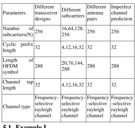
[image:4.595.311.544.515.736.2]This section is devoted for the performance analysis of the proposed systems. The proposed system’s performance has been studied under various scenarios. The impact of the number of subcarriers as well as the antenna configurations on the system have also been analyzed with the help of SNR vs BER plots. The effect of channel imperfections on the system’s performance has also been studied. The simulation parameters for the plots in this section are tabulated in table 1.
Table 1: Simulation Parameters
Parameters Different transceiver designs Different subcarriers Different antenna pairs Imperfect channel prediction
Number of subcarriers(N) 256
16,64,128,
256 256 256
Cyclic prefix
length 32 4,12,16,32 32 32
Length of OFDM symbol
288 20,76,144,
288 288 288
Channel tap
length 32 4,12,16,32 32 32
Channel type Frequency-selective rayleigh channel Frequency-selective rayleigh channel Frequency -selective rayleigh channel Frequency -selective rayleigh channel
5.1
Example I
International Journal of Computer Applications (0975 – 8887) Volume 43– No.19, April 2012
[image:5.595.96.501.328.525.2]have been analyzed. The analysis has been performed for a 2x2 MIMO OFDM configuration with 256 subcarriers for QPSK constellation. The simulation parameters are listed in Table 1.
Fig. 2 depicts the plot for this example. The designs have also been compared with benchmark techniques like linear SVD-ZFE transceivers and non-linear QR-SVD-ZFE transceivers. The advantage of GMD systems over other systems has been highlighted with the help of this plot. At an SNR of 8 dB, GMD-ZFE provides a BER nearly 10e-5 where as QR and SVD ZFE gives a BER of approximately 10e-4. The advantage of GMD-MMSE is more visible in the low SNR regime. At an SNR of 2 dB it is observed that GMD-MMSE outperforms all other systems. To achieve a BER of 10e-5 GMD-ZFE MIMO-OFDM system requires 8dB while other systems require an increase of 1 dB in SNR to achieve the same BER.
5.2
Example II
This example portrays the effect of number of subcarriers on the system’s performance.
The number of subcarriers utilized for OFDM transmission plays a vital role in determining the performance of the
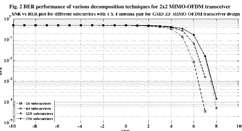
system. The variation in BER for different subcarriers for GMD-ZFE system has been simulated which is depicted in Fig. 3. The modulation scheme chosen was 64-QAM. At low range SNR, the system portrays same SNR for different number of subcarriers. Beyond 2 dB, a huge variation in the BER is observed for different subcarriers. At an SNR of 7 dB, the BER observed for 16 subcarriers is close to 10e-5whereas that observed for 64 subcarriers is nearly 10e-3. With 128 and 256 subcarriers it results in a BER only close to 10e-2 for the same SNR. Hence it is inferred that as the number of subcarriers increases, the BER increases.
The Fig. 4 gives the result for GMD-MMSE system with different subcarriers in the plot between SNR vs BER. QPSK is the modulation scheme that was deployed for this plot. It is observed that for the same modulation technique, system with 16 subcarriers shows better performance when compared to higher number of subcarriers. Hence it is inferred that as the number of subcarriers increase, the performance of the system degrades. At 9 dB SNR, the BER value for 256 subcarriers is approximately 10e-3 whereas for 128 subcarriers and 64 subcarriers it is in the range of 10e-4. The system with 16 subcarriers behaves the best when compared to the rest and gives a BER of approximately 10e-5.
Fig. 2 BER performance of various decomposition techniques for 2x2 MIMO-OFDM transceiver
[image:5.595.97.502.529.748.2]5.3
Example III
The number of transmitting and receiving antennas plays a vital role in the system’s performance. Hence as a part of our analysis in this section, we analyze the characteristics of both GMD-ZFE and GMD-MMSE systems.
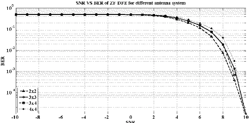
The performance of GMD-ZFE has also been analyzed for different antenna pairs such as 2X2, 3X3, 3X4 and 4X4. The simulation parameters are shown in Table.1 and the modulation scheme used is 64-QAM. From the Fig. 5, it is observed that for the same number of subcarriers, different antenna systems shows similar performance in terms of BER of value close to 10e-1 in the negative SNR region. The variation is observed from 0 dB. It is seen that as the number of transmitters and receivers increase, the performance degrades. From the analysis performed, 2x2 shows better performance when compared to 3x3, 3x4 and 4x4. At 9 dB, 2x2 system gives a BER slightly greater than 10e-3, 3x3 shows a BER nearing to 10e-3, 3x4 gives a value close to 10e-3 and 4x4 gives BER close to 10e-2. The worst case BER is given by 4x4 antenna system till 9 dB SNR.
The Fig. 6 depicts the SNR vs BER for GMD-MMSE system with different number of antenna pairs. The simulation parameters are listed in the table.1. From the graph, it is inferred that 2X2 system shows better performance when compared to higher configuration systems. 3x3 system provides higher BER value of 10e-2 at 10 dB when compared to 3x4 system with BER nearly 10e-3 At 9 dB, 3x3 and 4x4 systems behaves almost the same whereas 3x4 gives improvised BER of 10e-2.
5.4
Example IV
[image:6.595.96.501.310.509.2]The first and the foremost assumption involved in the proposed transceiver design is that the channel is perfectly known at the transmitter and at the receiver. Channel imperfections that evolve from estimation errors has a huge impact on the system’s performance. An analysis of the system would be incomplete without studying the effect of channel imperfection on the system’s behavior. In this example we analyze the robustness of transceiver designs with respect to channel variations.
Fig. 4 BER performance of the 2X2 GMD-MMSE MIMO OFDM design for different subcarriers
[image:6.595.93.502.536.738.2]International Journal of Computer Applications (0975 – 8887) Volume 43– No.19, April 2012
[image:7.595.97.501.305.507.2]Fig. 6 BER performance of the GMD-MMSE MIMO OFDM design with 256 subcarriers and different antenna pairs
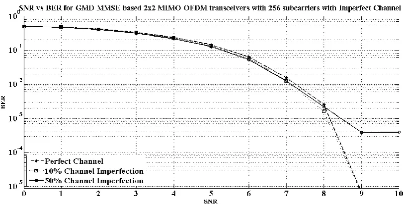
Fig. 7 BER performance of the 2X2 GMD-ZFE MIMO OFDM design with 256 subcarriers and imperfect channel estimation
[image:7.595.95.501.533.739.2]Fig. 7 shows the SNR vs BER plot for GMD-ZFE system with channel imperfections. It is observed that for 10% variation in the channel, the performance of the system with respect to the system where the estimation is perfect is almost same. As the imperfections increase, the GMD-ZFE system becomes vulnerable to errors. At an SNR of 8 dB, 50% imperfection gives a BER nearly equal to 10e-2 whereas in actual the system designed with perfect channel prediction gives a BER of in the range of 10e-3 to 10e-4.
Next, analyzing the GMD-MMSE system for its robustness, it is observed that there is less variation in the performance of the system even for 50% variation in the channel estimation. Fig. 8 substantiates this statement. At an SNR of 8 dB, the system with exact estimation and the one with 10%, 50% variation gives an BER nearly equal to 10e-3. Hence, using above examples the performance of the proposed systems in various dimensions has been analyzed.
6.
CONCLUSIONS
In this paper, we have proposed the transceiver design for the GMD based MIMO OFDM system with the ZF DFE and MMSE DFE. The performance analysis of these systems, using the SNR vs BER plots, proves that GMD performs better than the SVD and QR based transceiver designs. The GMD based systems are also evaluated for variable subcarriers in the OFDM modulation scheme and different antenna pairs. The results are lucidly summarized in the paper. The examination on the robustness of the system is done by introducing perturbations in the channel matrix, and it also entails the need for improving the system design by incorporating techniques to counter the imperfections in the channel.
7.
ACKNOWLEDGMENT
The authors are grateful to Mr.R.Ramanathan, Dr.M. Jayakumar and Mr.P.Sudheesh for their constructive criticism and valuable suggestions in the course of our work.
8.
REFERENCES
[1] Taewon Hwang, Chenyang Yang, Gang Wu, Shaoqian Li, and Geoffrey Ye Li,― OFDM and Its Wireless Applications: A Survey‖ ,IEEE Transactions On Vehicular Technology, Vol. 58, No. 4, May 2009 .
[2] Gordon L. Stüber, John R. Barry, Steve W.Mclaughlin, Ye (Geoffrey) Li, Mary Ann Ingram and Thomas G.Prat,
―Broadband MIMO-OFDM Wireless Communications‖, Proceedings Of The IEEE, Vol. 92, No. 2, February 2004. [3] Ching-Chih Weng, Chun-Yang Chen and P. P.
Vaidyanathan, ―MIMO Transceivers With Decision Feedback and Bit Loading: Theory and Optimization‖, IEEE Transactions On Signal Processing, Vol. 58, No. 3, March 2010.
[4] Yi Jiang, William W. Hager, Jian Li, ―The geometric mean
decomposition‖, Linear Algebra & Applications, Elsevier,2005.
[5] Chih-Hao Liu and P. P. Vaidyanathan, ―Zero-Forcing DFE Transceiver Design Over Slowly Time-Varying MIMO Channels Using ST-GTD‖, IEEE Transactions On Signal Processing, Vol. 58, No. 11, November 2010.
[6] Michael Botros Shenouda and Timothy N. Davidson, ―Frame work for designing MIMO systems with Decision feedback equalisation or Tomlinson-Harashima precoding‖, IEEE Journal On Selected Areas In Communications, Vol 26,No.2,February 2008.
[7] Y.Jiang, W.W.Hager, and J.Li, ―Generalized Triangular Decomposition‖, Math.Comput., October-2007
[8] Y.Jiang, W.W.Hager, and J.Li, ―Joint Transceiver Design for MIMO Communications Using Geometric mean Decomposition‖, IEEE transactions on Signal Processing, Vol.53, No.10, October 2005.
[9] Andrea Goldsmith, ―Wireless Communications‖ Cambridge University Press 2005.
[10]Antonio Pascual Iserte, ―Channel State Information and Joint transceiver Design in Multi-Antenna Systems‖, Ph.D.Thesis December-2004.
[11]Chih-Hao Liu and P. P. Vaidyanathan , ―MMSE DFE Transceiver Design Over Slowly Time-Varying MIMO Channels Using ST-GTD‖, IEEE transactions on Signal Processing, Vol. 59, No. 1, January 2011.
[12]S. Zhou and G. B. Giannakis, ―How accurate channel prediction needs to be for transmit-beamforming with adaptive modulation over Rayleigh MIMO channels?,‖ IEEE Trans. Wireless Commun., Vol. 3, No. 3, pp. 1285– 1294, Jul. 2004.
[13]C. H. Liu and P. P. Vaidyanathan, ―Generalized Geometric Mean Decomposition and DFE MMSE Transceiver Design for cyclic prefix systems‖ in ICASSP 2011 [14]Part 11: Wireless LAN Medium Access Control (MAC)
and Physical Layer (PHY) Specifications: High-Speed Physical Layer in the 5 GHz Band, IEEE Standard 802.11a-1999.