Automatic Brick Making Machine
P.Manoj Kumar
1,P.Naveen Kumar
2, P.Pavithran
3, Dr.G.Rajamurugan4
1,2.3 UG student of Bannari Amman Institute of Technology, Sathyamangalam
4Associate Professor, Dept of mechanical engineering, Bannari Amman Institute of Technology, Sathyamangalam
---***---Abstract - In olden days or even now, most of the brick making industries use human power to make bricks. If it is very few number of bricks it is easy and advisable to use human power but when it is huge in numbers only machines can perform faster, and easily than human. Continuous working of workers leads to fatigue. By considering the above difficulty we have introduced a new concept called automatic brick making machine. This project is designed by following blocks, Control unit, Worm gear, Induction Motor, Pneumatic cylinder, screw conveyor, Brick die, Blade, Proximity sensor, Bearing.
1.INTRODUCTION
The main objective of this project is to perform various machine operations using machine with the help of pneumatic sources. For a developing industry the operation performed and the parts (or) components produced should have it minimum possible production cost, and then only industry runs profitably. Automation can be achieved through computers, hydraulics, pneumatics, robotics, etc., of these sources, pneumatics form an attractive medium for low cost automation. The main advantages of all pneumatic systems are economy and simplicity. Automation plays an important role in mass production. Nowadays almost all the manufacturing process is being atomized in order to deliver the products at a faster rate. The manufacturing operation is being atomized for the following reasons.
To achieve mass production To reduce man power
To increase the efficiency of the plant To reduce the work load
To reduce the production cost
1.1.Pneumatics
Today pneumatics is mainly understood to means the application of air as a working medium in industry especially the driving and controlling of machines and equipment. Pneumatics has for some considerable time between used for carrying out the simplest mechanical tasks in more recent times has played a more important role in the development of pneumatic technology for automation. Pneumatic systems operate on a supply of compressed air which must be made available in sufficient quantity and at a pressure to suit the capacity of the
system. When the pneumatic system is being adopted for the first time, however it wills indeed the necessary to deal with the question of compressed air supply. The key part of any facility for supply of compressed air is by means using reciprocating compressor. A compressor is a machine that takes in air, gas at a certain pressure and delivered the air at a high pressure. Compressor capacity is the actual quantity of air compressed and delivered and the volume expressed is that of that of the air at intake conditions namely at atmosphere pressure and normal ambient temperature.
1.2.Selection of Pneumatics
Mechanization is broadly defined as the replacement of manual effort by mechanical power. Pneumatic is an attractive medium for low Cost mechanization particularly for sequential (or) repetitive operations. Many factories and plants already have a compressed air system, which is capable of providing the power (or) energy requirements and control system (although equally pneumatic control systems may be economic and can be advantageously applied to other forms of power). The main advantages of an all pneumatic system are usually Economic and simplicity the latter reducing maintenance to a low level.
1.3.Pneumatic Power
Pneumatic systems use pressurized gases to transmit and control power. Pneumatic systems typically use air as the fluid medium because air is safe, low cost and readily available.
1.4.Reciprocating Compressors
2. DESCRIPTION OF EQUIPMENTS
2.1.Induction Motor
An induction motor (IM) is a type of alternating current motor where power is supplied to the rotating device by means of electromagnetic induction. It is also called asynchronous motor. An electric motor converts electrical power to mechanical power in its rotor (rotating part). There are several ways to supply power to the rotor. In a DC motor this power is supplied to the armature directly from a DC source, while in an induction motor this power is induced in the rotating device. An induction motor is sometimes called a rotating transformer because the stator (stationary part) is essentially the primary side of the transformer and the rotor (rotating part) is the secondary side. Induction motors are widely used, especially polyphase induction motors, which are frequently used in industrial drives. Induction motors are now the preferred choice for industrial motors due to their rugged construction, absence of brushes (which are required in most DC motors) and — thanks to modern power electronics — the ability to control the speed of the motor.
2.2.Air Cylinder
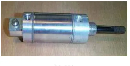
[image:2.596.323.550.79.194.2]There are only two main kinds of air cylinders: Double acting, and single acting. They come in all variations, shapes and sizes. Both kinds are useful for haunt work. Double acting cylinders are useful when you need to push in both directions, and single acting cylinders are useful when only a push in one direction is needed. And, sometimes 'in a pinch', you can adapt a double to act as a single, and a single to act as a double. Air cylinders are measured by three main values: "pressure rating", the "bore", and "stroke" . There are lots of calculations to accurately figure the power of a cylinder, but most haunt pop-up applications can be handled by air cylinders in the range of 3/4" to 1-1/2" bore, and 3" to 8" stroke. Power measurements primarily take into account the air pressure (the higher the pressure, the more power); and the bore (the larger the bore - the more power). The power ratings are usually only quoted at maximum pressure. So if a cylinder produces180 pounds of 'push', it will only deliver that at the maximum pressure (usually 250 psi for commercial cylinders). Haunters should work their props to work and much, much lower pressures. A good goal is not to exceed 60-70psi for working props. Going much higher causes more stress on the prop and all parts in the air system, and make your compressor run more often. Even at lower pressures, air cylinders can still move very fast and deliver quite a lot push, so always be very careful around pneumatics. Double Acting means the air cylinder rod is 'pushed' out, and 'pushed' in.
Figure 1
Every double acting air cylinder has these basic parts. A cylinder to hold everything together, a 'plunger' that the air pushes against, two connections to get the air in and out, and a rod that goes in and out. That's it. Here's a simple animation to illustrate the motion. As air is sent into the left connection (pressure is shown in yellow), it pushes against the plunger and the rod goes out. At the same time, air is released out of the right connection. To reverse the motion, air is sent into the right connection, pushing against the plunger on the other side and the rod is forced back in.
2.3.Solenoid Valves
This valve has five flow paths. One pressure port, two exhaust ports two cylinder ports and body with five internal passage and a moving part, a spool. The cylinder port A will be connected to pressure port, with the spool in one extreme position. At the same time the cylinder B is connected to exhaust port when the spool is moved to another extreme position, the cylinder port B will be connected to pressure port.
2.4.Worm Gear
A worm gear is type of mechanical gear. Worm gears are used when large gear reductions are needed. It is common for worm gears to have reductions of 20:1, and even up to 300:1 or greater. Many worm gears have an interesting property that no other gear set has: the worm can easily turn the gear, but the gear cannot turn the worm. This is because the angle on the worm is so shallow that when the gear tries to spin it, the friction between the gear and the worm holds the worm in place. Very interesting usage of worm gears is in the torsion differential, which is used on some high-performance cars and trucks. A gear consisting of a spirally threaded shaft and a wheel with marginal teeth that meshes into it. The toothed wheel of this gear a worm wheel. Compact structure saves mounting space. Highly accurate. Runs forward and backward. High overload capacity. Stable transmission with reduced vibration and noise.
2.5.Screw Conveyor
in many bulk handling industries. Screw conveyors in modern industry are often used horizontally or at a slight incline as an efficient way to move semi-solid materials, including food waste, wood chips, aggregates, cereal grains, animal feed, boiler ash, meat and bone meal, municipal solid waste, and many others. The first type of screw conveyor was the Archimedean screw, used since ancient times to pump irrigation water. They usually consist of a trough or tube containing either a spiral blade coiled around a shaft, driven at one end and held at the other, or a "shaftless spiral", driven at one end and free at the other. The rate of volume transfer is proportional to the rotation rate of the shaft. In industrial control applications the device is often used as a variable rate feeder by varying the rotation rate of the shaft to deliver a measured rate or quantity of material into a process. Screw conveyors can be operated with the flow of material inclined upward. When space allows, this is a very economical method of elevating and conveying. As the angle of inclination increases, the allowable capacity of a given unit rapidly decreases. The rotating part of the conveyor is sometimes called simply an auger.
2.6.Proximity Sensor
A Proximity sensor can detect objects without physical contact. A proximity sensor often emits an electromagnetic field or beam and look for changes in the field. The object being sensed is often referred to as the proximity sensor's target. Different proximity sensor targets demand different sensors. For example, a capacitive or photoelectric sensor might be suitable for a plastic target; an inductive proximity sensor requires a metal target. In capacitive proximity sensors, the sensed object changes the dielectric constant between two plates. A proximity sensor has a range , which is usually quoted relative to water. Because changes in capacitance take a relatively long time to detect, the upper switching range of a proximity sensor is about 50 Hz. The proximity sensor is often found in bulk-handling machines, level detectors, and package detection. One advantage of capacitive proximity sensors is that they are unaffected by dust or opaque containers, allowing them to replace optical devices. A typical capacitive proximity sensor has a 10-mm sensing range and is 30 mm in diameter. The proximity sensor incorporates a potentiometer to allow fine tuning of the sensing range and can repetitively detect objects within 0.01 mm of the set point. Switching frequency is 10 Hz, and operating temperature range is -14 to 158°F. Conditioning the output of a proximity sensor has always been difficult. Proximity sensor designers must confront linearity, hysteresis, excitation voltage instability, and voltage offset. A proximity sensor that measures current flow between the sensing electrode and the target provides readouts in appropriate engineering units. Usually, one side of the voltage source or oscillator connects to the sensing electrode, and the other side connects through a current-measuring circuit to the target, which generally is a metal part at earth or ground potential. Probes used with a
capacitive proximity sensor have either a flat disc or rectangular sensing element surrounded by a guard electrode that provides electrical isolation between the proximity sensor and its housing. The guard also ensures that the lines of electrostatic field emanating from the probe are parallel and perpendicular to the surface of the proximity sensor. Capacitance proximity sensor systems can make measurements in 100 µsec with resolutions to 10-7 in. (0.001 micron). Probe diameters range from a few thousandths of an inch to several feet for corresponding measurements ranging from thousandths of an inch to several feet.
2.7.Bearing
A bearing is a device to permit constrained relative motion between two parts, typically rotation or linear movement. Bearings may be classified broadly according to the motions they allow and according to their principle of operation. Low friction bearings are often important for efficiency, to reduce wear and to facilitate high speeds. Essentially, a bearing can reduce friction by virtue of its shape, by its material, or by introducing and containing a fluid between surfaces. By shape, gains advantage usually by using spheres or rollers. By material, exploits the nature of the bearing material used. Sliding bearings, usually called bushes bushings journal bearings sleeve bearings rifle bearings or plain bearings, rolling-element bearings such as ball bearings and roller bearings. Jewel bearings, in which the load is carried by rolling the axle slightly off-center. fluid bearings, in which the load is carried by a gas or liquid magnetic bearings, in which the load is carried by a magnetic field. Flexure bearings, in which the motion is supported by a load element which bends. Bearings vary greatly over the forces and speeds that they can support. Forces can be radial, axial (thrust bearings) or moments perpendicular to the main axis. Bearings very typically involve some degree of relative movement between surfaces, and different types have limits as to the maximum relative surface speeds they can handle, and this can be specified as a speed in ft/s or m/s. The moving parts there is considerable overlap between capabilities, but plain bearings can generally handle the lowest speeds while rolling element bearings are faster, hydrostatic bearings faster still, followed by gas bearings and finally magnetic bearings which have no known upper speed limit.
2.8.Micro Controller
conceivable directions, making it ubiquitous. As a consequence, it has generate a great deal of interest and enthusiasm among students, teachers and practicing engineers, creating an acute education need for imparting the knowledge of microcontroller based system design and development. It identifies the vital features responsible for their tremendous impact, the acute educational need created by them and provides a glimpse of the major application area. A microcontroller is a complete microprocessor system built on a single IC. Microcontrollers were developed to meet a need for microprocessors to be put into low cost products.
2.9.Air Compressor
Compressor is the air producing machine. They collect the airs from the atmosphere are in the running of machine are engine. Air compressors are utilized to raise the pressure of a volume of air. Air compressors are available in many configurations and will operate over a very wide range of flow rates and pressures. Compressed air was expelled by primitive man to give glowing embers sufficient oxygen to allow them to flare up into a fire. During the compression process, the temperature increases as the pressure increases. This is known as polytypic compression. The amount of compression power also increases as the temperature increases. Compressors are staged thereby reducing the temperature rise and improving the compression efficiency. The temperature of the air leaving each stage is cooled prior to entering the next stage. This cooling process is called intercooling. Volumetric efficiency also increases with multi-stage compression since the pressure ratio over the first stage will be decreased. Selection of the air compressor is only the first step in designing an efficient and reliable compressed air system. The air exiting the compressor is saturated with moisture and will have compressor lubricants (lubricated compressors only). Other chemicals that may have been drawn into the compressor intake may also be present. This contamination is harmful to many processes, pneumatic tools, instruments and equipment. Air purification equipment, filters, air dryers, breathing air purifiers, monitoring equipment, used alone or in combination will remove these contaminants. Selection and purchase of the compressor and necessary purification equipment can be easily done on the Compressed air site. Our application engineers are ready to answer all of your questions and to assist you in placing your order. And it work in the process of rotating the fan and the piston movement with the help of current supply.
Figure 2
4. WORKING PRINCIPLE
In our model Induction motor plays a main role. The sand and water mixture is loaded in the funnel. The funnel outlet leads to a screw conveyor which is placed horizontally. The screw conveyor mixes the sand and water thoroughly. After the above process the mixture is allowed to pass to through the outlet. As said above after the outlet is opened the mixture is transferred to the next stage where the shape of brick can be achieved. The mixture is dropped in the brick die. A pneumatic cylinder with cutting plate is arranged in such a manner that it cutting the sand mixture in the die to form a rectangular shape. The pneumatic cylinder is ctuated with the help of a compressed air and the solenoid valve. The valve can be operated by the electric supply. The solenoid valve changes the direction of the air supply to the pneumatic cylinder. When the air is allowed to pass to the rear side of the cylinder the forward stroke occurs and when the air is passed to the front side the return stroke occurs. All this above process leads to make a brick. These operations can perform by the timing control. The whole operation is controlled by the microcontroller.
The project carried out by us made an impressing task in the field of brick making industries. It is very useful for making brick very easy. This project will reduce the cost involved in the concern. Project has been designed to perform the entire requirement task at the shortest time available.
3. DRAWING
REFERENCE :
[1] Rai Mohan, Dinesh Chandra, R. L. Gupta and S. K. Jain, “Production of Calcium Silicate Bricks from Fly Ash”, National Workshop on Utilization of Fly Ash, Roorkee, A59- A62, 1988.
[2] E. Douglas and G. Pouskoueli, “Prediction of Compressive Strength of Mortars Made with Portland Cement Blast Furnace Slag-Fly Ash Blends”, Cement and Concrete Research, 21(4), pp.523-534, 1991.
[3] B. K. Sahu and K. Swarnadhipathi, “Use of Botswana Fly Ash as Flow Able Fill”, Proceedings of the ASTM Publications STP1459 on Innovations in Controlled LowStrength Materials, USA, pp.41-50, and 2004.
[4] B. K. Sahu, “Use of Fly Ash for Stabilizing Sub-Standard Road Construction Materials in Botswana”, Proceedings of the International Congress on Fly Ash, India, New Delhi, VIII, 10,1-VIII 10.9, 2005.
[5] F. Tutunlu and U. Atalay, “Utilisation of Fly Ash in Manufacturing of Bricks”, International Ash Utilization Symposium, Center for Applied Energy Research, University of Kentucky, Paper 13, 2001.
[6] S. Chakraverty, Himani Saini and S.K. Panigrahi, “Predicting Product Parameters of Fly Ash-Cementsand Bricks”, Construction Materials, Proceedings of Institution of Civil Engineers, U.K 160 issue CM2, pp.65-74, 2007.
[7] P.K. Chaulia and Reeta Das, “Process Parameter Optimization for Fly Ash Brick by Taguchi Method”, Materials Research, 11(2), São Carlos Apr. /June 2008.
[8] C-Brick Making Machine From “www.cbri.org.in/ cbrick.htm”.
[9] Baumann V., Bauer G. E. A., “The Performance of Foundations on Various Soils Stabilized by the VibroCompaction Method”, Canadian Geotechnical Journal, 11: 509-530, 10.1139/t74-056, 1974.
[10] M.F. Ashby, Y.J.M. Brechet, D. Cebon and L. Salvoc., “Selection Strategies for Materials and Processes”, Elsevier J Mater Des, 2004; 25: 5167.