© 2017, IRJET | Impact Factor value: 5.181 | ISO 9001:2008 Certified Journal | Page 3329
An Experimental Analysis and Optimization of Process Parameters on
Friction Stir Welding of Dissimilar AA6061-T6 and AA6951-T6 Using
Taguchi Technique
Surjeet Singh
1, Kamaljit Singh
2, ishavneet Singh
3Charan Shivesh
41,4
Research Scholar, Mechanical Engg. Dept. BUEST, Baddi, H.P, (India)
2,3
Assistant Professor, Mechanical Engg. Dept. BUEST, Baddi, H.P, (India)
---***---Abstract -
Aluminum alloys are broadly used in aerospace industry, automotive industry, railways and in marine industry due to its resistance to corrosion, light weight and high strength to weight ratio. The aim of the present research is to optimize the process parameters for higher tensile strength and to analyze the effect of process parameters such as tool rotational speed, welding speed and tool tilt angle on the tensile strength of friction stir weldments. Taguchi L9 orthogonal array was used to conduct the experiments.
The optimum process parameters for the maximum tensile strength of the joints were predicted, and the individual significance of each process parameter on the tensile strength of the friction stir weldment was evaluated by using the signal-to-noise ratio and analysis of variance (ANOVA) results.Key Words: Friction Stir Welding, Dissimilar Joining,
Rotational Speed, Welding Speed, Tool Tilt Angle, Tensile Strength
1. INTRODUCTION
The dissimilar joining of metals with different thermo-mechanical and chemical properties is often more challenging as it results in the formation of brittle intermetallic compounds. Joining of aluminum (Al) or its alloys with copper (Cu) is preferred in many applications in engineering [1].
In aircraft and automotive structures friction stir welded lap joints have been widely used with the aim to replace riveted
lap joints by using aluminium alloys. Rivet holes are often
potential sites for crackinitiation or corrosion problems; moreover, the elimination of fasteners leads to considerable weight and cost savings. A few examples of FSW joints applied in automotive industries are some applications include engines, wheel rims and lap joints in car back supports
Friction Stir Welding (FSW) is a solid welding process invented by The Welding Institute (TWI) in 1991 [2]. In the Friction Stir Welding process, a non-consumable, rotating tool with a specific geometry is plunged into and traversed through the material. The two key components of the tool are the shoulder and the pin (probe). During welding, the pin travels in the material, while the shoulder rubs along the
surface. Heat is generated by the tool shoulder rubbing on the surface and by the pin mixing the material below the shoulder. This mixing action permits the material to be transferred across the joint line, allowing a weld to be made without any melting of the material.
1.1
Principle of Friction Stir Welding
Friction Stir Welding is a solid-state process, which means that the objects are joined before reaching the melting point. In FSW process, a cylindrical-shouldered tool, with a profiled probe (nib or pin) is rotated at a constant speed and fed at a constant traverse rate into the joint line between two pieces of sheet or plate material. The parts to be joined are clamped rigidly in order to prevent the joint faces from being forced apart. The tool pin length is kept slightly less than the weld depth required so that there should be an intimate contact of shoulder with the work surface.
[image:1.595.313.555.468.687.2]
Fig -1: Principle of friction stir welding [3]
© 2017, IRJET | Impact Factor value: 5.181 | ISO 9001:2008 Certified Journal | Page 3330
adiabatic heat within the material, cause the stirredmaterials to soften without reaching the melting point. As the pin is pushed toward welding, the primary face of the pin, assisted by an exceptional pin profile, forces plasticized material to the back of the pin while applying an substantial forging force to consolidate the weld metal. The welding of the material is empowered by plastic deformation in the solid state.
2. EXPERIMENTAL DETAILS
[image:2.595.308.558.92.391.2]The material used for the research work was aluminum alloy AA6061-T6 and AA6951-T6 of 6mm thick sheets. The chemical and mechanical properties of the material are shown in table 1 and table 2 respectively.
Table -1: Chemical properties of AA6061 and AA6951
Element Weight %
AA6061-T6 AA6951-T6
Si 0.7 0.399
Mg 0.99 0.398
Cu 0.21 0.115
Mn 0.12 0.0427
Zn 0.088 0.268
Cr 0.6 0.0173
[image:2.595.35.288.313.499.2]Al Remaining Remaining
Table -2: Mechanical properties of AA6061 and AA6951
Properties AA6061-T6 AA6951-T6
Tensile Strength MPa 360 270
Yield Strength MPa 276 230
Hardness HRB 60 50
Elongation % 17 13
The friction stir welding was performed on vertical milling machine shown in figure 2. Welds were made by joining two (110 x 75 x 6) mm plates to make a weld joint of size 150 mm wide and 110 mmlong.
Fig -2: Friction stir welding on vertical milling machine
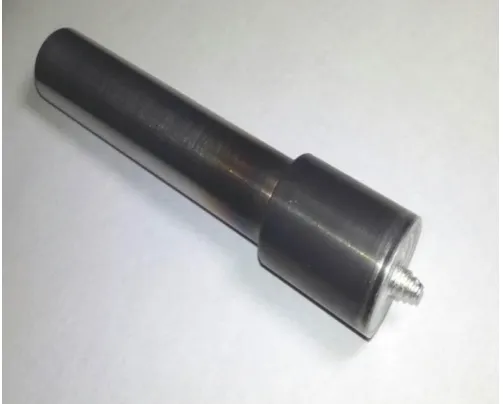
In this investigation a tapered threaded cylindrical tool was used. The tool was made up of H-13 Steel with a shoulder diameter of 18mm and 5.8mm pin length. The threaded cylindrical pin was tapered from the root diameter of 6 mm to the top diameter of 4.8 mm as shown in figure 3. The three parameters such as rotational speed, transverse speed and tool tilt angle are taken into consideration, the parametric rage and their levels are listed in Table 3.
[image:2.595.308.560.531.733.2]© 2017, IRJET | Impact Factor value: 5.181 | ISO 9001:2008 Certified Journal | Page 3331
Table -3: Process parameter and their levelsParameters Level 1 Level 2 Level 3
Rotational speed
(rpm) 1540 1950 2300
Welding speed
(mm/min) 25 35 35
Tool tilt angle
(degree) 0 0.5 1.0
2.1 Taguchi’s Method
The Taguchi method was used to optimise the welding parameters. This method is a time-saving technique to optimise the process parameters. In this method, an appropriate orthogonal array should be selected depending on the total degree of freedom (DOF). The degree of freedom for the orthogonal array should be greater than or at least equal to those for the process parameters. So, L9 orthogonal array was selected which has a degree of freedom of 8. Nine experimental runs were conducted as per Taguchi L9 orthogonal array.
2.2 Analysis of Variance (ANOVA)
Analysis of variance (ANOVA) test was performed to identify the process parameters that are statistically significant. The purpose of the ANOVA test is to investigate the significance of the process parameters which affect the tensile strength, impact strength and hardness of FSW joints. The results of ANOVA indicate that the considered process parameters are highly significant factors affecting the tensile strength, impact strength and hardness of FSW joints.
2.3 S/N Ratio
Taguchi also recommended analysing the valued using S/N ratio. It involves conceptual approach which graphs the effect and identifies the significant values.
2
1
10 log
j ijk
n
y
n
where n is the number of tests and Yijk is the experimental value of the ith quality characteristics in the jth experiment at the kth test.
In this study, the S/N ratio was chosen according to the criterion of the larger the- better, in order to maximize the response.
Table -4: Taguchi’s L9 orthogonal array
Sr. No. Rotational speed Welding speed Tool tilt angle
1 1 1 1
2 1 2 2
3 1 3 3
4 2 1 2
5 2 2 3
6 2 3 1
7 3 1 3
8 3 2 1
9 3 3 2
2.4 Tensile Testing of the Weld Joints
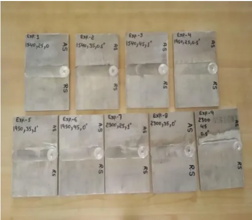
All weld joints were prepared as per the design matrix and test specimens from these joints were prepared for mechanical testing. The weldments are shown in figure 4.
Fig -4: Friction stir weldments
[image:3.595.308.559.422.641.2]© 2017, IRJET | Impact Factor value: 5.181 | ISO 9001:2008 Certified Journal | Page 3332
Table -5: Experimental results for tensile strengthSr. No. Rotational Speed (rpm) Welding Speed WS (mm/min) Tool Tilt Angle (Degree) Tensile Strength (MPa) S/N Ratio
1 1540 25 0.0 124 41.86
2 1540 35 0.5 123 41.79
3 1540 45 1.0 119 41.51
4 1950 25 0.5 129 42.21
5 1950 35 1.0 140 42.92
6 1950 45 0.0 127 42.07
7 2300 25 1.0 130 42.27
8 2300 35 0.0 152 43.63
9 2300 45 0.5 131 42.34
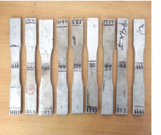
Tensile test samples were prepared from welds joints according to the ASTM E-8 specification, Data from each weld specimens was recorded as values of yield strength, tensile strength and percentage elongation. A universal testing machine is used to test the tensile stress strength of material. It is named after the fact that it can perform many standard tensile and compression tests on materials, components, and structures.
Table -6 Analysis of variance for S/N Ratio
Table -7 Response Table for Signal to Noise Ratios (Larger is better)
Fig -5: Tensile test specimen
Levels RPM WS Angle
1 41.73 42.12 42.53
2 42.40 42.79 42.12
3 42.75 41.98 42.24
Delta 1.03 0.81 0.41
Rank 1 2 3
Source DF Seq
SS Adj SS F P Contribution RPM 2 377.5 377.5 5.2 0.16 47.30%
WS 2 278.2 278.2 3.8 0.20 34.85%
Angle 2 70.2 70.2 0.9 0.50 8.79%
Residu
al Error 2 72.2 72.2 9.04%
[image:4.595.38.301.511.731.2]© 2017, IRJET | Impact Factor value: 5.181 | ISO 9001:2008 Certified Journal | Page 3333
2300 1950 1540 42.9 42.6 42.3 42.0 41.7 45 35 25 1.0 0.5 0.0 42.9 42.6 42.3 42.0 41.7 RPM M e a n o f S N r a ti o s WS AngleMain Effects Plot for SN ratios
Data Means
Signal-to-noise: Larger is better
Fig -6: Represents the effect of parameters on S/N ratio of tensile strength
From figure 6 it is observed that the tensile strength of the weldment increases with the increase in the tool rotational speed. But in case of welding speed the tensile strength once increases and then decreases immediately. When the welding lies in between 25 mm/min to 35 mm/min tensile strength increases. On further increase in welding speed from 35 mm/min to 45 mm/min tensile strength decreases. It can be seen that with the increase in tool tilt angle the tensile strength decreases. When the tool tilt angle lies in between 0˚ to 0.5˚ tensile strength decreases slightly but on increasing the tool tilt angle from 0.5˚ to 1.0˚ the tensile strength a little increases.
From the table 7 and figure 6 it can be concluded that tool rotational speed of 2300 rpm, welding speed of 35 mm/min and tool tilt angle 0˚ is the optimum welding condition to get a higher tensile strength.
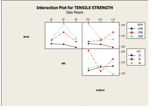
Interaction plot for tensile strength
45 35
25 0.0 0.5 1.0 150 135 120 150 135 120 RPM WS A NGLE 1540 1950 2300 RPM 25 35 45 WS Interaction Plot for TENSILE STRENGTH
Data Means
Fig -7: Interaction plot for tensile strength
Relationship between tool rotational speed and welding speed
When tool rotational speed is 1540 rpm and welding speed is in between 25 mm/min to 35 mm/min there is slight decrease in tensile strength. When welding speed is in between 35 mm/min to 45 mm/min. the tensile strength decreases. It can be seen that at 1950 rpm tool rotational speed and is in between 25 mm/min. to 35 mm/min welding speed there is increase in tensile strength. However, when welding speed lies between 35 mm/min to 45 mm/min the tensile strength decreases immediately. For 2300 rpm tool rotational speed and welding speed is in between 25 mm/min to 35 mm/min there is drastically increase in tensile strength. It can be seen that at welding speed between 35 mm/min to 45 mm/min the tensile strength decreases sharply.
Relationship between tool rotational speed and tool tilt angle
At tool rotational speed of 1540 rpm and tool tilt angle is lies in between 0˚ to 0.5˚ there is slight decrease in tensile strength and when tool tilt angle is in between 0.5˚ to 1.0˚ the tensile strength decreases. For 1950 rpm tool rotational speed and tool tilt angle is in between 0.5˚ to 1.0˚ there is immediately increase in tensile strength and when tool tilt angle is in between 0.5˚ to 1.0˚ the tensile strength decreases. It is observed that when tool rotational speed is 2300 rpm and tool tilt angle lies in between 0.5˚ to 1.0˚ there is drastically decrease in tensile strength. Also when the tool tilt angle is lies in between 0.5˚ to 1.0˚ the tensile strength decrease slightly.
Relationship between welding speed and tool tilt angle
It can be seen from figure 7 when tool welding speed is 25 mm/min and tool tilt angle is in between 0.5˚ to 1.0˚ there is slightly increase in tensile strength. With the increase in the angle from 0.5˚ to 1.0˚ the tensile strength increase a little. When welding speed is 35 mm/min and tool tilt angle is in between 0.5˚ to 1.0˚ there is slightly increase in tensile strength. By increasing the tool tilt angle from 0.5˚ to 1.0˚ the tensile strength increases drastically. For welding speed of 25 mm/min and tool tilt angle is in between 0.5˚ to 1.0˚ there is extremely decrease in tensile strength. And when tool tilt angle is in between 0.5˚ to 1.0˚ the tensile strength decrease a little.
3 CONCLUSIONS
[image:5.595.37.289.102.282.2] [image:5.595.34.291.569.755.2]© 2017, IRJET | Impact Factor value: 5.181 | ISO 9001:2008 Certified Journal | Page 3334
was used to obtain optimal condition for Friction StirWelding of AA6061-T6 to AA6951-T6 aluminium alloy. Experimental results were evaluated using ANOVA. From the tensile strength investigations the following conclusions can be drawn:-
1. A maximum tensile strength was exhibited by the friction stir welded joints fabricated with the optimized parameters of 2300 r/min rotational speed, 35 mm/min welding speed and tool tilt angle 0˚.
2.
Tool rotational speed plays a vital role and contributes 47.30% to the overall contribution and welding speed & tool tilt angle have 34.85%, 8.79% influence on tensile strength of joint respectively.REFERENCES
[1] P. K. Sahu, K. Kumari, S. Pal, and S. K. Pal, “Hybrid fuzzy-grey-Taguchi based multi weld quality optimization of Al/Cu dissimilar friction stir welded joints,” Adv. Manuf., vol. 4, no. 3, pp. 237–247, 2016.
[2] Mishra RS, Ma ZY. Friction stir welding and processing. Mater Sci Eng: R: Rep 2005;50:1–78.
[3] S. Eslami, T. Ramos, P. J. Tavares, and P. M. G. P. Moreira, “Effect of friction stir welding parameters with newly developed tool for lap joint of dissimilar polymers,” Procedia Eng., vol. 114, no. September, pp. 199–207, 2015.
[4] H. Liu, Y. Hu, C. Dou, and D. P. Sekulic, “An effect of the rotation speed on microstructure and mechanical properties of the friction stir welded 2060-T8 Al-Li alloy,” Mater. Charact., vol. 123, pp. 9– 19, 2017.
[5] A. Yazdipour and A. Heidarzadeh, “Effect of friction stir welding on microstructure and mechanical properties of dissimilar Al 5083-H321 and 316L stainless steel alloy joints,” J. Alloys Compd., vol. 680, pp. 595–603, 2016.
[6] L. Giraud, H. Robe, C. Claudin, C. Desrayaud, P. Bocher, and E. Feulvarch, “Investigation into the dissimilar friction stir welding of AA7020-T651 and AA6060-T6,” J. Mater.Process. Technol., vol. 235, pp. 220–230, 2016.
[7] P. K. Sahu, K. Kumari, S. Pal, and S. K. Pal, “Hybrid fuzzy-grey-Taguchi based multi weld quality optimization of Al/Cu dissimilar friction stir welded joints,” Adv. Manuf., vol. 4, no. 3, pp. 237–247, 2016. [8] N. Z. Khan, Z. A. Khan, and A. N. Siddiquee, “Effect of Shoulder Diameter to Pin Diameter (D/d) Ratio on Tensile Strength of Friction Stir Welded 6063 Aluminium Alloy,” Mater. Today Proc., vol. 2, no. 4–5, pp. 1450–1457, 2015.
[9] S. M. Bayazid, H. Farhangi, and A. Ghahramani, “Investigation of Friction Stir Welding Parameters of
6063-7075 Aluminum Alloys by Taguchi Method,” Procedia Mater. Sci., vol. 11, no. 2010, pp. 6–11, 2015.
[10] R. Kadaganchi, M. R. Gankidi, and H. Gokhale, “Optimization of process parameters of aluminum alloy AA 2014-T6 friction stir welds by response surface methodology,” Def. Technol., vol. 11, no. 3, pp. 209–219, 2015.
[11] E. Salari, M. Jahazi, A. Khodabandeh, and H. Ghasemi-Nanesa, “Influence of tool geometry and rotational speed on mechanical properties and defect formation in friction stir lap welded 5456 aluminum alloy sheets,” Mater. Des., vol. 58, pp. 381–389, 2014. [12] B. Parida and S. Pal, “Fuzzy assisted grey Taguchi approach for optimisation of multiple weld quality properties in friction stir welding process,” Sci. Technol. Weld. Join., vol. 20, no. 1, pp. 35–41, 2014. [13] R. K. Kesharwani, S. K. Panda, and S. K. Pal, “Multi
Objective Optimization of Friction Stir Welding Parameters for Joining of Two Dissimilar Thin Aluminum Sheets,” Procedia Mater. Sci., vol. 6, no. Icmpc, pp. 178–187, 2014.
[14] M. Dehghani, S. A. A. A. Mousavi, and A. Amadeh, “Effects of welding parameters and tool geometry on properties of 3003-H18 aluminum alloy to mild steel friction stir weld,” Trans. Nonferrous Met. Soc. China (English Ed., vol. 23, no. 7, pp. 1957–1965, 2013. [15] M. H. Shojaeefard, A. Khalkhali, M. Akbari, and M.
Tahani, “Application of Taguchi optimization technique in determining aluminum to brass friction stir welding parameters,” Mater. Des., vol. 52, pp. 587–592, 2013.
[16] M. Koilraj, V. Sundareswaran, S. Vijayan, and S. R. Koteswara Rao, “Friction stir welding of dissimilar aluminum alloys AA2219 to AA5083 - Optimization of process parameters using Taguchi technique,” Mater. Des., vol. 42, pp. 1–7, 2012.
[17] X. W. Li, D. T. Zhang, C. Qiu, and W. Zhang, “Microstructure and mechanical properties of dissimilar pure copper/1350 aluminum alloy butt joints by friction stir welding,” Trans. Nonferrous Met. Soc. China (English Ed., vol. 22, no. 6, pp. 1298– 1306, 2012.
[18] J. C. Park and S. J. Kim, “Optimization of friction stir welding with the various welding parameters for Al-Mg alloys,” Rare Met., vol. 30, no. SUPPL.1, pp. 628– 632, 2011.
[19] M. S. Moghaddam, R. Parvizi, M. Haddad-Sabzevar, and A. Davoodi, “Microstructural and mechanical properties of friction stir welded Cu-30Zn brass alloy at various feed speeds: Influence of stir bands,” Mater. Des., vol. 32, no. 5, pp. 2749–2755, 2011. [20] I. N. Tansel, M. Demetgul, H. Okuyucu, and A. Yapici,
© 2017, IRJET | Impact Factor value: 5.181 | ISO 9001:2008 Certified Journal | Page 3335
[21] S. Vijayan, R. Raju, and S. R. K. Rao, “MultiobjectiveOptimization of Friction Stir Welding Process Parameters on Aluminum Alloy AA 5083 Using Taguchi-Based Grey Relation Analysis,” Mater. Manuf. Process., vol. 25, no. 11, pp. 1206–1212, 2010. [22] T. Sakthivel, G. S. Sengar, and J. Mukhopadhyay, “Effect of welding speed on microstructure and mechanical properties of friction-stir-welded aluminum,” Int. J. Adv. Manuf. Technol., vol. 43, no. 5– 6, pp. 468–473, 2009.
[23] P. M. G. P. Moreira, T. Santos, S. M. O. Tavares, V. Richter-Trummer, P. Vilaça, and P. M. S. T. de Castro, “Mechanical and metallurgical characterization of friction stir welding joints of AA6061-T6 with AA6082-T6,” Mater. Des., vol. 30, no. 1, pp. 180–187, 2009.
[24] A. K. Lakshminarayanan and V. Balasubramanian, “Process parameters optimization for friction stir welding of RDE-40 aluminium alloy using Taguchi technique,” Trans. Nonferrous Met. Soc. China, vol. 18, no. 3, pp. 548–554, 2008.
[25] K. Kumar and S. V. Kailas, “The role of friction stir welding tool on material flow and weld formation,” Mater. Sci. Eng. A, vol. 485, no. 1–2, pp. 367–374, 2008.
[26] L. Ceschini, I. Boromei, G. Minak, A. Morri, and F. Tarterini, “Effect of friction stir welding on microstructure, tensile and fatigue properties of the AA7005/10 vol.%Al2O3p composite,” Compos. Sci. Technol., vol. 67, no. 3–4, pp. 605–615, 2007. [27] M. Cabibbo, H. J. McQueen, E. Evangelista, S.
Spigarelli, M. Di Paola, and A. Falchero, “Microstructure and mechanical property studies of AA6056 friction stir welded plate,” Mater. Sci. Eng. A, vol. 460–461, pp. 86–94, 2007.
[28] P. Cavaliere, G. Campanile, F. Panella, and A. Squillace, “Effect of welding parameters on mechanical and microstructural properties of AA6056 joints produced by Friction Stir Welding,” J. Mater. Process. Technol., vol. 180, no. 1–3, pp. 263–
270, 2006.
[29] J. Yan, Z. Xu, Z. Li, L. Li, and S. Yang, “Microstructure characteristics and performance of dissimilar welds between magnesium alloy and aluminum formed by friction stirring,” Scr. Mater., vol. 53, no. 5, pp. 585– 589, 2005.
![Fig -1: Principle of friction stir welding [3]](https://thumb-us.123doks.com/thumbv2/123dok_us/8158356.804867/1.595.313.555.468.687/fig-principle-friction-stir-welding.webp)