© 2017, IRJET | Impact Factor value: 5.181 | ISO 9001:2008 Certified Journal
| Page 1609
Design and Weight optimization of Pinion by using FEA Method
Mr. Dattatray A. Patil
1, Prof. Dalwe D.M.
21
P.G. Student, Department of Mechanical Engineering, S.T.B.’s College of Engineering
Tuljapur, Dist. Osmanabad, Maharashtra, India.
2
Assistant Professor, Department of Mechanical Engineering, S.T.B.’s COE Tuljapur, Maharashtra, India.
---***---Abstract:
A spur gear is generally subjected to bendingstress which causes failure. However it is observed that performance of the spur gear is not satisfactory in certain applications and therefore it is required to explore some alternate materials to improve the performance of the spur gears. Composite materials provide adequate strength with weight reduction and they are emerging as a better alternative for replacing metallic gears. This work includes design and weight optimization of output pinion of dual rotor wind turbine. In Cad software modeling is done and for post processing we are used Ansys software. We are compared the analytical result with FEA result. For the design and weight reduction we are replaced existing material with composite material. We are analyzed bending stress ,total Strain and weight for both existing material and composite material. From the analysis it is concluded that bending stress developed in pinion gear tooth subjected to fixed load is independent of material.
Key words: Dual rotor wind turbine, glass fiber, Finite Element Method, Design and Weight Optimization.
1. INTRODUCTION
Gears are mechanical components used for transmitting motion and torque from one shaft to another. Ever since invention of rotating machines, gears existed. During early states that around 2600 BC Chinese used gears to measure the speeds of chariots. In 250 B.C. Archimedes used a screw to drive toothed wheels which were used in engines of war. In 4th Century B.C., Aristotle used gears to stimulate astronomical ratios. Greek and Roman literature mention the extensive use of gears in clock of cathedrals and ecclesiastical buildings. During early centuries gears made of either wood or stone teeth set in wood. Later during metal ages Iron, Bronze or tin were used instead of stone. There is no standard procedure for gear manufacturing until 1835 when English inventor Whitworth patented the first gear hobbing process. Although gear manufacturing has achieve lots of advancements during its evolution, however the failure of gear due to bending and contact stress still remained challenge for designers and manufacturers until 1892.
In 1892 the Philadelphia Engineers Club first recognized Wilfred Lewis presentation of stresses on the gear tooth and it still serve as the basis to determine the gears stress. The Lewis bending equation has a lot of drawbacks which
[image:1.595.339.535.450.641.2]include 1. Load on gear tooth is dynamic and is influenced by pitch line velocity 2. The entire load is carried on single tooth. 3. The equation of application of load is not true as the load is shared by the tooth. 4. The stress concentration factor at tooth fillet is not considered. Apart from this aspect for the application of gears in dual rotor wind turbine gear box, bending stress, total deformation and weight of gears are considered for the efficiency of wind turbine. As turbine is increased, in this work bending stress, total deformation and weight of gear is lesser final output of wind turbine is increased. As bending stress, total deformation and weight of gear is lesser final output of weight of pinion is analyzed. Analytical results of existing materials are compared with FEA results of composite material. For the existing material cast iron, plain carbon steel results are compared with software based results of glass fiber as composite material are calculated and compared. From this analysis we can say that Ansys software can be used for analysis comparison purposes.
Fig. 1 Pinion of Dual rotor wind Turbine Gearbox.
2. LITERATURE REVIEW
© 2017, IRJET | Impact Factor value: 5.181 | ISO 9001:2008 Certified Journal
| Page 1610
methods can potentially provide more accurate solutionssince they normally required much less restrictive assumptions. They have created 3D model by Pro-E software can generate models of three dimensional gears easily. It is concluded that sets of gears having same module and pressure angle can be created and assembled together. By creating 3D deformable body of spur gear results are checked with theoretical calculation data ,simulation results have good agreement with theoretical results. This study provides future studies on contact stresses. From this study numerically obtained values of distributions are comparable with theoretical results.
M. Keerthi, K. Sandya, K. Srinivas [2] In this project work is done on composite material spur gear, values of deformation and vonmisses stresses are calculated for both composite material and existing material. Static analysis is performed to determine the deformation and Von-misses stresses. Modal analysis is performed to determine the natural frequencies and mode shapes. The results were validated with theoretical calculations by Lewis equation. It was concluded that the stress values are calculated for composite materials is approximately same as compared to the structural steel, gray cast iron and aluminum alloy. So from these analysis results, we conclude that, the stress induced, deformation and weight of the composite spur gear is almost same as compared to the structural steel spur gear, gray cast iron spur gear and aluminum alloy spur gear. So, Composite materials are capable of using in automobile vehicle gear boxes instead of existing cast steel gears with better results.
Mr. Kishor N. Naik, Prof. Dhananjay Dolas, [3] The main objective of this paper is to analyze the bending stresses occur on the gear tooth profile of gear used in gear box of special purpose machine also effect on bending stress by variation of the gear parameters. Face width and root radius are taken gear parameters, how stress redistribution are taken place by varying this parameter studied. The stresses are calculated with the help of the FEA this result are compared with the stresses calculated by Lewis equation. For this work parametric modeling is done using Pro-E 5.0 and for analysis ANSYS 12.0 workbench is used. This work helpful to conclude Effect of bending stress on gear tooth profile by variation of gear parameters also give the comparison of FEM method with analytical calculation. Effect of bending stress on gear tooth profile by variation of gear parameters also give the comparison of FEM method with analytical calculation.
Vivek Karaveer, Ashish Mogrekar and T. Preman Reynold Joseph, [4] This paper presents the stress analysis of mating teeth of spur gear to find maximum contact stress in the gear teeth. The results obtained from Finite Element Analysis (FEA) are compared with theoretical Hertzian equation values. For the analysis, steel and grey cast iron are used as the materials of spur gear. The spur gears are sketched, modeled and assembled in ANSYS Design
Modeler. As Finite Element Method (FEM) is the easy and accurate technique for stress analysis, FEA is done in finite element software ANSYS 14.5. Also deformation for steel and grey cast iron is obtained as efficiency of the gear depends on its deformation. The results show that the difference between maximum contact stresses obtained from Hertz equation and Finite Element Analysis is very less and it is acceptable.
S.Mahendran, K.M.Eazhil, L.Senthil Kumar, [5] work has been carried out on spur gear to study the weight reduction and stress distribution for cast steel and composite materials. In this project analysis of both cast steel and composite materials are analyzed in the application of gear box used in automobile vehicles. From these analysis we got values stress, deformation, and weight of composite materials are less as compared to cast steel spur gear.
Pradeep Kumar Singh, Manwendra Gautam, Gangasagar and Shyam BihariLal, [6] A pair of spur gear tooth in action is generally subjected to two types of cyclic stress: contact stress and bending stress including bending fatigue. Both stress may not attain their maximum values at the same point of contact fatigue. These types of failure can be minimized by analysis of the problem during the design stage and creating proper tooth surface profile with proper manufacturing methods. In this paper using ansys work bench software, bending stress, contact stress and static load on the tooth of spur gear drive is found.
Devikant Baviskar, [7] This work presents the design and Analysis of polymer PEK spur gear and Comparison of results of PEK with Metallic Cast Iron under limited loading conditions. Application of Plastic gear reduces the weight and noise vibration. Analytical Method is used to calculate Tooth load with help of Lewis equation & dynamic tooth load with help of Buckingham equation. Gear profile modeling is done by using SOLIDWORKS 2015.
3. OBJECTIVES
° To propose a composite material for spur gear which will have increased strength and durability as compared to conventional material.
° To prove the conventional methods of analysis are comparable with FEA methods.
© 2017, IRJET | Impact Factor value: 5.181 | ISO 9001:2008 Certified Journal
| Page 1611
4. MATERIAL SELECTION
4.1 Cast Iron
Table 1.
Material properties for Cast Iron
PROPERTIES
VALUES
ELASTIC MODULUS,E
1.2 x 10
5MPa
POISONS RATIO,µ
0.3
YIELD STRESS
250 MPa
ULTIMATE TENSILE STRESS
320 MPa
DENSITY,
ρ
7850 kg/m3
4.2 Cast Iron
Table 2.
Material properties for Carbon Steel
PROPERTIES
VALUES
ELASTIC MODULUS,E
1.65x10
5MPa
POISONS RATIO,µ
0.26
YIELD STRESS
250 MPa
ULTIMATE TENSILE STRESS
320-350
MPa
DENSITY,
ρ
7200 kg/m3
4.1 Cast Iron
Table 3.
Material properties for Glass Fiber
PROPERTIES
VALUES
ELASTIC MODULUS,E
1.9X10
5MPa
YIELD STRESS
N/A
ULTIMATE
TENSILE
STRESS
1600 MPa
DENSITY,ρ
1600 kg/m3
5. ANALYTICAL ANALYSIS
5.1 Specifications of Dual Rotor Wind Turbine:
[literature]
Power (P) = 4309.65 W Speed (ng) = 195 RPM Gear Ratio(¡) = 5 ¡ = np/ ng 5= 195/ ng
Speed (np) = 975 RPM Power (P) = 2π nt / 60 4309.65 = (2π x 975 t) / 60
Torque (t) = (4309.65 x 60)/ (2π x 975) t= 42200 N-mm
Step-1) Deciding the weaker between Pinion & Gear since same material is used for the Pinion & Gear, Pinion is weaker than the Gear.
Assume no. of teeth on pinion Zp = 14 (Practically) ¢ = 200 From design data book Lewis form factor for the 14 teeth Yp = 0.276
Also no. of teeth on Gear , ¡ = Zg / Zp
5= Zg / 14
Zp = 70
Step-2) Estimation of module based on beam strength
Assume pitch line velocity υ = 5 m/s Velocity factor Cυ = 3/3+υ = 3/3+5 = 3/8
From design data book service factor Cs = 1.5 Module (m) = 60*106/ п { (KW* Cs* fs)/ Zg *np Cυ (b/m)*(Sut/3)* Yp}
Also factor of safety fs=2, b= 10m, Sut = 1600 N/mm2
Module (m) = 60*106/ п { (4.30965* 1.5* 2)/ 975*14 (3/8)*10*(1600/3)*0.276}
Module (m) = 3.2001 mm
Step 3) Selection of module
From design data book, standard value of the module is 3.5 mm
d = Pitch circle dia. of pinion = No. of teeth x module = 14 x 3.5 = 49 mm
Face width b = 10m= 10*3.5= 35 mm t = Pt * (d/2)
Pt= t/ (d/2) Pt=42200 /24.5 Pt= 1722.44 N
Where ‘Pt’ is the Tangential load Using Lewis equation
© 2017, IRJET | Impact Factor value: 5.181 | ISO 9001:2008 Certified Journal
| Page 1612
Pt = m b.бb.Y
1722.44 = 3.5 x 54 x бb x 0.276
бb = 1722.44/ 0.276 x 3.5 x 54
бb = 33 N/mm2
The Maximum allowable stress as per the design of the desired Pinion gear is,
= 33N/mm2 (Induced Stress)
Where бb = permissible bending stress Y’ is the Lewis form factor
‘b’ is the face width of the gear
‘d’ is the pitch circle diameter of the gear
Allowable stress of Cast iron (high grade) =Ultimate tensile strength / 2
= 320 / 3 = 106.67 N/mm2
33 N/mm2< 106.67 N/mm2
Allowable stress of Plain Carbon Steel =Ultimate tensile strength /1.5
= 460/3
= 153.34 N/mm2
33N/mm2 < 153.34 N/mm2
Allowable stress of Glass Fiber =Ultimate tensile strength / 3
= 1600/3 = 533.34 N/mm2
33N/mm2 < 533.34 N/mm2
So the design is safe
Note that the bending stress developed in a Pinion gear tooth subjected to a fixed load is independent of the material properties, while the deflection depends on the material property E. Hence the bending stress is same whether it is made of a Cast Iron, Plain Carbon Steel and Glass Fiber, but the strain would be different.
5.2 Calculations of bending stress and strain at
loading Condition.
5.2.1 Calculations for Cast Iron Pinion Gear
- Bending Stress at Pt=1722.44 NPt= m b.бb.Y
1722.44= 3.5 x 35 x бb x 0.276 бb = 1722.44/ 0.276 x 3.5x 35
бb = 50.94 N/mm2………..bending stress
-Strain at Pt=1722.44 N
бb = E x є
50.94 = 1.2 x 10⁵x є
є = 0.42 x 10⁻³………..strain
5.2.2 Calculations for Plain Carbon Steel Gear
- Bending Stress at Pt=1722.44N
Pt= m b.бb.Y
1722.44= 3.5 x 35 x бb x 0.276 бb = 1722.44/ 0.276 x 3.5x 35
бb = 50.94 N/mm2………..bending stress
-Strain at Pt=1722.44N
бb = E x є 50.94 = 2.1 x 10⁵ x є
є = 0.267 x 10⁻³………..strain
5.2.3 Calculations for Glass Fiber Pinion Gear
- Bending Stress at Pt=1722.44N
Pt= m b.бb.Y
1722.44= 3.5 x 54 x бb x 0.276 бb = 1722.44/ 0.276 x 3.5x 35
бb = 50.94 N/mm2………..bending stress
-Strain at Pt=1722.44 N
бb = E x є 50.94 = 1.9 x 10⁵ x є
є =0.268 x 10⁻³………..strain
5.2.4
Evaluation of Mass
5.2.4.1 For Cast Iron Material
m = density (9) * volume (v) m = 7850*6.67*10-5
m = 0.524 Kg
5.2.4.2 For Plain Carbon Steel Material m = density (9) * volume (v) m = 7200*6.65*10-5
m = 0.4752 Kg
5.2.4.3 For Plain Glass Fiber Material m = density (9) * volume (v) m = 1600*6.67*10-5
m = 0.107 Kg
6. SIMULATION WORK
6.1 Cad Model generation:
© 2017, IRJET | Impact Factor value: 5.181 | ISO 9001:2008 Certified Journal
| Page 1613
6.2 Design of Pinion gear
Design of output Pinion gear:
Number of teeth’s (z) = 14 Module (m) = 3.5 mm Pressure angle standard (α) = 20° Pitch circle diameter (D) = z*m = 14*3.5 = 49 mm Base circle diameter (Db) = D cos α= 49*cos (20o) = 46.045 mm
Outer diameter (Do) = (z+2)*m = (14+2)*3.5 = 56mm
Diametral pitch (Pd) =
=
=
= 0.286 mm Circular pitch (C) = =
= 3.5 * 3.142= 10.997 mm
Addendum (a) = =
= = 3.5 mm Dedendum (b) =
=
=
= 4.04 mm
Total depth (dt) =
=
=
= 7.542 mm Working depth (dw) =
=
=
= 6.993 mm
Thickness of tooth (T) =
=
=
= 5.492 mm
Face width (F) = = = = 28
mm
Face width (F) = = = = 56
mm
Face width should be in between the range 28 and 56. Face width (F) =
= 3.5 = 43.988 mm
Clearance (C) = =
=
= 0.7 mmRoot diameter = =
=
= 42 mm
6.3 Parametric Modeling of Spur Gear
Parameters
No of teeth (N) =14 Module (m) = 3.5 mm
Pitch Circle radius Rp = m* N/2 Clearance Circle radius Rb = 0.94 * Rp Addendum Circle radius Ra = Rp + m Dedendum Circle Radius Rd = Rp – 1.25 * m Pressure angle (α) = 20 degrees………..Angle1 Angle 2 = 90/N = 6.42 deg.
© 2017, IRJET | Impact Factor value: 5.181 | ISO 9001:2008 Certified Journal
| Page 1614
Fig.2 CAD Model6.4 Processing (Solution Stage)
Apply Boundary Conditions
Constrains : Define Structural Displacement Zero
Fig.3 Constraints
[image:6.595.314.561.144.386.2]A. Stress,Deformation and Weight Results for Cast Iron
Fig. 4 Bending Stress 53.17 N/mm2 at load 1722.44 N (Cast Iron)
[image:6.595.35.306.363.514.2]Max. Bending stress value for C.I. Pinion gear is 53.17 N/mm2 which is less than max. Allowable stress hence design is safe.
Fig.5 Strain 0.43x 10 -3at load of 1722.44 N (Cast Iron) From fig. value of strain for C.I. is 0.43x10⁻³
[image:6.595.317.560.436.705.2] [image:6.595.34.283.599.730.2]© 2017, IRJET | Impact Factor value: 5.181 | ISO 9001:2008 Certified Journal
| Page 1615
B . Stress,Strain and Weight Results for Carbon [image:7.595.318.557.132.287.2]Steel
Fig. 7 Bending Stress 53.40 N/mm2 at load 1722.44N (Carbon Steel)
Max. Bending stress value for Carbon Steel Pinion gear is 53.40 N/mm2 which is less than max. Allowable stress hence design is safe.
Fig. 8 Strain 0.347 x 10 -3at load 1722.44N (Carbon Steel) From fig. value of strain for Carbon
steel is 0.347x10⁻³
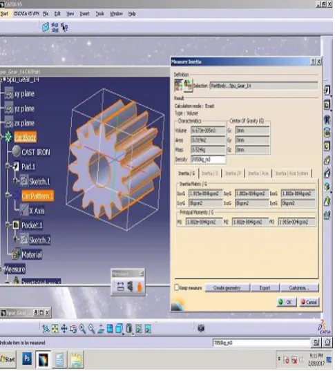
[image:7.595.37.297.133.267.2]Fig.9 Weight of Pinion Gear in Catia Software (Carbon Steel) from fig. value of weight is 0.48 Kg
[image:7.595.35.298.363.511.2]C. Stress,Deformation and Weight Results for Glass Fiber
Fig.10 Bending Stress 53.40 N/mm2 at load 1722.44N (Glass Fiber)
Max. Bending stress value for Glass Fiber Pinion gear is 53.40 N/mm2 which is less than max. Allowable stress hence design is safe.
Fig.11 Strain 0.365 x 10 -3at load 1722.44N (Glass Fiber) From fig. value of strain for C.I. is 0.365x10⁻³
[image:7.595.314.571.381.519.2] [image:7.595.317.545.569.724.2] [image:7.595.42.278.570.712.2]
© 2017, IRJET | Impact Factor value: 5.181 | ISO 9001:2008 Certified Journal
| Page 1616
7. RESULT VALIDATION
Table 4. Comparison of FEA and Analytical Result
Sr.
No. Material FEA Max. Bending Stress Analytical Stress 1 Existing
Cast Iron 53.17 MPa 50.94 MPa 2 Existing
Carbon
Steel 53.40 MPa 50.94 MPa
3 Glass Fiber 53.40 MPa 50.94 MPa
Table 5. Comparison of FEA and Analytical Result
Sr.
No. Material FEA Strain Analytical Strain
1 Existing
Cast Iron 0.43x 10 -3 0.42x10⁻³
2 Existing
Carbon Steel 0.267x10⁻³ 0.347 x 10 -3
3 Glass Fiber 0.365*10-3 0.271x10⁻³
Table 6. Comparison of FEA and Analytical Result
Sr.
No. Material Software Catia Weight
Analytical Weight 1 Existing
Cast Iron 0.524 Kg 0.524 Kg
2 Existing
Carbon Steel 0.48 Kg 0.475 Kg
3 Glass Fiber 0.107 Kg 0.107 Kg
8. CONCLUSION
• The objective of current work is to replace existing material with glass fiber composite material for pinion gear for gear box of dual rotor wind turbine.
• For design and weight optimization analytical and finite element method is applied for determining bending stress, strain.
• The obtained analytical results are compared with FEA results and found both results are comparable.
• Ansys software can be used for analysis purposes. • From these analysis value of strain for glass fiber is less as compare to existing material for same loading conditions.
• Calculated value of bending stress is independent on material.
• Weight optimization is achieved drastically with glass fiber in place of existing material.
REFERENCES
1. Mrs.Shinde S.P., Mr. Nikam A.A. , Mr. Mulla T.S, “Static Analysis of Spur Gear Using Finite Element Analysis”,Journal of Mechanical and Civil Engineering (IOSR-JMCE) ISSN: 2278-1684, PP: 26-31.
2. M. Keerthi, K. Sandya, K. Srinivas “Static & Dynamic Analysis of Spur Gear using Different Materials”, International Research Journal of Engineering and Technology, e-ISSN: 2395-0056
3. Mr. Kishor N. Naik, Prof. DhananjayDolas, “Static Analysis Bending Stress on Gear Tooth Profile By Variation of Gear Parameters With The Help of FEA”, International Journal of Engineering Research&Technology,ISSN:22780181 Vol.3 Issue 6, June – 2014.
4. VivekKaraveer,Ashish Mogrekar and T. PremanReynold Joseph, “Modeling and Finite Element Analysis of Spur Gear”, International Journal of Current Engineering and Technology. ISSN 2277 – 4106.
5. S.Mahendran, K.M.Eazhil, L.Senthil Kumar, “Design and Analysis of Composite Spur Gear”, ISSN 2321 – 2705, Volume I, Issue VI, November 2014.
6. Pradeep Kumar Singh, Manwendra Gautam, Gangasagar and Shyam BihariLal, “Stress Analysis Spur Gear Design By Using Ansys Workbench” International journal of mechanical engineering and robotics research. ISSN 2278 – 0149, Vol. 3, No. 3, July 2014.