NEW MODEL TRANSFORMATION USING REQUIREMENT
TRACEBILITY FROM REQUIREMENT TO UML
BEHAVIORAL DESIGN
1
NURI JAZULI KAMARUDIN, 2NOR FAZLIDA MOHD SANI, 3RODZIAH ATAN,
4
NORAINI CHE PA
Department of Computer Science, Department of Information System University of Putra Malaysia, 43400 Selangor, Malaysia E-mail: [email protected] ,[email protected], 3
4
ABSTRACT
Model transformation (MT) has become an important concern in Software Engineering [1], because it is related to system design. Model transformation can be used in many different application scenarios, for instance, to provide interoperability between models of different size and complexity [2]. Traditionally, model transformations are done for purposes such as code generation, refinement, and refactoring [3]. Currently, there are researches on Model Transformation from Requirement to Use Case diagram, Use Case description to Activity diagram and Use Case to Sequence Diagram and many more. However, the research is based on only one specific output and not comprehensive as it should be because it only converts the requirement into one specific Unified Modeling Language (UML) diagram at a time. Transformation model need one important approach, which is the requirement traceability in order to trace the keywords as input before automatically converted into UML diagram. In this paper, we propose an approach and tool to transform the requirement into UML model that are Use Case diagram and Activity diagram since there are still not exist the transformation which is required from requirement into behavioral UML diagram called RETRANS. It is different from the existing program because this tool will convert the requirement into two different UML diagrams at a time which is not provided by the existing tool.. We have also come out with a framework as the main guidance for developing this project.
Keywords:Model transformation (MT), UML model, Requirement traceability.
1. INTRODUCTION
Unified Modeling Language (UML) diagrams play an important role in software development. UML is an object modeling language for specifying, constructing, visualizing, and documenting the artifacts of software-intensive system [4] .Commonly used UML diagrams are the Use Case, Activity and Class diagrams. Use case and activity diagrams model the behavioral aspect of the system, whereas, Class diagrams represent the static design of a system [5]. During the standard’s development, the requirements evolved to include support for model-driven development (MDD) [6].
The realization of model-driven-software development requires effective techniques for implementing code generators for domain-specific languages [7]. Model transformations are central components in model-driven software development.
Model transformations can be used in many different application scenarios, for instance, to provide interoperability between models of different size and complexity. As a consequence, they are becoming more and more complex [2].
The core technique is code generation by model transformation, that is, the generation of a structured representation (model) of the target program instead of plain text [7]. These transformations are often created manually. A semi automatic process based on well-defined patterns brings many advantages: it accelerates the development time of transformations, diminishes the errors that may occur in manual coding, and increases the quality of transformational code [2].
both a forwards and backwards direction [8]. It has been defined as the ‘ability to follow the life of a requirement in both a forward and backward direction’ in order to understand the origins of the requirement and also to determine how a requirement has been realized in downstream work products such as design, code and test cases [9].
As what has been mentioned before, our objectives are to come out with an approach and tool to transform the requirement into UML design. However there are few problems arise. First problem is to choose the best technique to trace the keywords from the requirement. The main problem is, how to make our project to be different with other project since there are lots of developments in model transformation.
Our project is to present the initial development on our project called RETRANS to facilitate system designer in designing the system.
We explain the field that related in our projects in section 2. Section 3 describes the framework that we used in developing our tool and section 4 is about Java Library and initial result of our project. The conclusion is summarized in our last section.
2. LITERATURE REVIEW
A. UML
Many new fields in computer science have been discovered. It has led to the emergence of a variety of new software. Although the software world has become advanced, UML still be used in development. UML is an object modeling language for specifying, constructing, visualizing, and documenting the artifacts of software-intensive system [10]. Commonly used UML diagrams are – Use case, Activity and Class Diagram. Use case and activity diagrams model the behavioral aspect of the system, whereas, Class diagrams represent the static design of a system [5]. .
In this research, the result would be only use case, activity and state diagram. Software design can be achieved by analysis of functional requirements. UML is a general-purpose modeling language that models real-world objects [13]. The unified Modeling Language (UML) has become a de-facto standard notation for describing analysis and design models of object-oriented software systems [11]. As UML is becoming the de-facto language for software design, it is important to have a sufficiently rich linguistic structure to model security specifications accurately [12].
UML uses graphical notations to describe the system providing abstraction by suppressing the lower level details. Graphical models are easy to understand, and if necessary re-implementation of design can be done with a minimum knowledge [13]. However the fact that UML lacks a precise semantics is a serious drawback of UML-based techniques. UML, being visual in nature, is easy to understand and communicate but, it lacks the rigor of formal modeling languages and hence verification of a model specified in UML and ensuring requirement traceability within these models becomes difficult [5]. The serious disadvantage of UML is its semiformal syntax and semantics [4]. Modeling from different viewpoints, successive refinements and the absence of formal semantics give rise of vertical, horizontal, syntactic and semantic consistency problems.
B. MODEL TRANSFORMATION
Model transformations are frequently applied in business process modeling to bridge between language on a different level of abstraction and formality [14]. Model transformations can be used in many different application scenarios, for instance, to provide interoperability between models of different size and complexity .As a consequence, they are becoming more and more complex.
The main benefit stemming from a successful m-transformation (model transformation) [15]. A few of the benefits that stated in that paper are better information flow between systems, improved customer projected image, rapid and dynamic customization of products and services being offered by the organization. Model transformation helps to ensure a repeatable and scientific basis for product testing gives good coverage of all the behavior of the product and allow tests to be linked directly to requirements [3].
C. REQUIREMENT TRACEABILITY
One of approach that used in this project is requirement traceability. Requirements traceability helps developers to control and manage the development and evolution of a software system. It has been defined as the ‘ability to follow the life of a requirement in both a forward and backward direction’ in order to understand the origins of the requirement and also to determine how a requirement has been realized in downstream work products such as design, code and test cases[9].
Despite a growth in specialized tools, and inflated claims of RT functionality from tool vendors, their use is not as widespread in practice as the importance of RT would suggest [18]. It was found that traceability problems primarily occurred as a result of breakdowns in communication between developers who were hard-pressed for time [3]. A tool chain that is able to generate and to follow traceability links across model to model and model to code transformations, and capable of providing navigability support along these traceability links [19]. They also provide the explanation on how low level requirements to which a certain source code block traces back to by selecting the given source code block.
3. PROPOSED FRAMEWORK OF
RETRANS.
As what has been mentioned before, the objective of this research is to automatically convert user requirement into UML diagram. In order to have a well constructed project, we have come out with a new framework to guide us in proving the approach and developing the tools that we proposed. The framework divided into 3 phases. First is Requirement phase, second is Use case phase, and the lastly is Activity phase.
The framework only covers completely the tool construction. As the figure 1.0 shows, the tools will start with the requirement. The tool will trace keywords from user requirement that will be used in creating use cases and activity diagram. The tool only traced keywords that related that is actor and activity. The tool will specify which keywords are for the use case(s) and which keyword is for the actor(s).
Second phase in the framework is use case part. This phase focused on creating the use case. The tool will collect the keyword that has been traced before to be as an input. Using the use case library technique, the tool will arrange the input as use case(s) and actor(s). The last step in this phase
is, the tool will connect the use case and actor that has been arranged earlier.
Lastly is activity diagram part. The input for this phase is from the use case diagram that has been drawn before. Using the activity diagram library, the tool will create activity diagram for each use case.
4. JAVA LIBRARY NEEDED AND
INNITIAL RESULT
In this research, we are using java libraries for each output that will be generated. A library is a reusable software component that saves developers time by providing access to the code that performs a programming task. Libraries exist to assist with many different types of tasks. Use case and activity diagram will be the main output and each of them will have their own class libraries. We are creating the libraries because we want to divide each output’s class into specific class because we want each library to be reusable library because it is related with each others. For example, activity diagram that will be generated in this research are depending on each use case form use case diagram.
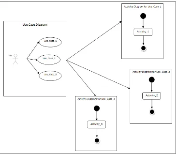
For use case diagram library, the components are actor and use case. Use case class library will be used after the detection of the keywords form the requirement. The keyword will first detect the actor and use case(s) for the requirement, and the library will generated the diagram by connect the actor and use case(s) from the keywords. Figure 3.0 shows the illustration of the process.
For activity diagram, the process will take part after the use case diagram has been generated. Firstly, the system will specify each use case that involved in the use case diagram. Then, it will generate the activity diagram by connect each component inside the class library (activity). Figure 3.1 shows the illustration of the process.
In file menu contains instructions such as open file and exit. The ‘NEXT’ button at the bottom of the interface is also included . There will be added improvements on this tool since this tool is still in development process.
5. CONCLUSION
In this paper, we present about our approach in transforming the requirement into UML diagram (use case and activity diagrams). We have summarized the fields that are related to our project. We have also come out with a new framework and java class library in order to help us proving our approach. The approach will help software developer reducing their time in design process.
Acknowledgement
This work is supported by Research University Grant Scheme (RUGS) received from the Universiti Putra Malaysia. The principle investigator of the research project is Dr. Nor Fazlida Mohd Sani.
REFERENCES:
[1] M.Kessentini, H.Sahraoui, M.Boukadoum, and O.B.Omar, “Search-based model transformation by example”, Software and
Systems Modeling (SoSyM), Vol.11 Issue 2,
May 2012, pp.209-226.
[2] M.D.D.Fabro and P.Valduriez, “Towards the efficient development of model transformations using model weaving and matching transformations”, Software and
Systems Modeling, Vol.8, July 1, 2009,
pp.305-324.
[3] E.G.Aydal and J.Woodcock, “Automation of Model-Based testing through Model Transformation”, Testing:Academic and Industrial Conference- Practice and Research
Technique, September 4-6,2009, pp.63.
[4] B.Roussev, “Generating OCL Specifications and Class Diagrams from Use Cases: A Newtonian Approach”, Proceedings HICSS’03
Proceedings of the 36th Annual Hawaii
International Conference on System Sciences
(HICSS’03), Vol 9, 2003, pp.321.2.
[5] J. Chanda, A. Kanjilal, S. Sengupta, and S. Bhattacharya, “ Traceability of requirements and consistency verification of UML use case, activity and Class diagram: A Formal approach”, Proceeding of International Conference on Methods and Models in
Computer Science, January 22, 2010, pp. 1-4.
[6] R.B. France, S. Ghosh, T. Dinh-Trong, and A. Solberg, “Model-driven development using UML 2.0: promises and pitfalls”, IEEE
Computer Society, Vol.39, issue 2, February
2006, pp. 59-66.
[7] Z. Hemel, L.C.L Kats, D.M. Groenewegen, and E. Visser, “Code Generation by Model Transformation: A Case Study in Transformation Modularity”, Software and
System Modeling, Vol.9, Issue 3, 2010, pp.
375-402.
[8] L. Kong and T. Yuan, “Extension Features-Driven Use Case Model for requirement traceability”, International Conference on Computer Science & Education ICCSE ’09,
July 25-28, 2009, pp. 866-870.
[9] J.C. Huang, “Just Enough Requirements Traceability”, Computer Software and Applications Conference COMPSAC ’06,
Vol.1, September 17-21, 2006, pp.41-42. [10]Object management group, OMG unified
modeling Language specification, Version 1.4,SPET.2001, http://www.omg.org
Software Engineering (ASE 2001),November 26-29,2001, pp. 289-296.
[12]K. Algathbar, “Enhancement of Use Case Diagram to Capture Authorization Requirement”, International Conference on Software Engineering Advance, ICSEA ’09,
September 20-25, 2009, pp.394- 400.
[13]A. Vemulapalli and N. Subramanian, “Transforming Functional Requirement from UML into BPEL to Efficiently Develop SOA- Based Systems”, OTM ’09 Proceedings of the
Confederated International Workshops, 2009,
pp. 337-349.
[14]M. Fanchao, C. Dianhui and Z. Dechen, “Transformation from Data Flow Diagram to UML 2.0 Activity Diagram”, International Conference on Progress in Informatics and
Computing (PIC), Vol. 2, December 10-12,
2010, pp. 1010-1014.
[15]I. Marmaridis and B. Unhelkar, “Challenges in mobile transformations: a requirement modeling perspective for small and medium enterprises”, International Conference on
Mobile Business ICMB 2005, July 11-13, 2005,
pp.16-22.
[16]K. Czarnecki and S.Helsen,” Classification of Model Transformation Approaches”, OOPSLA ‘03Workshop on Generative Techniques in the
Context of Model-Driven Architecture, 2003.
[17]T. Yue, L.C. Briand, and Y. Labiche, “An automated Approach to Transform Use Cases into Activity Diagrams”, Proceedings 6th
European Conference,ECMFA 2010, Vol.
6138, June 15-18,2010
[18]O.C.Z. Gotel, “An analysis of the requirements traceability problem”, International Conference on Requirement Engineering 2004,
April 18-22, 1994, pp. 94-101.
[19]T. Levendovszky, D. Balasubramanian, K. Smyth, F. Shi and G. Karsai, “ A transformation instance-based approach to traceability”, ECMFA-TW-’10 Proceedings of
the 6th ECMFA Traceability Workshop, 2010,
APPENDIX
[image:6.612.103.507.62.634.2]Figure 1 Framework For Tool Developing.
Figure 3.0 Process Of Generating Use Case Diagram By Using Class Library (Use Case)
[image:7.612.117.483.322.644.2]![Figure 2.0 Running Examples [17]](https://thumb-us.123doks.com/thumbv2/123dok_us/8915571.961605/6.612.103.507.62.634/figure-running-examples.webp)