ISSN: 1992-8645 www.jatit.org E-ISSN: 1817-3195
QUAD-BAND MICROSTRIP ANTENNA FOR MOBILE
HANDSETS
1ASEM S. AL-ZOUBI, 2MOHAMED A. MOHARRAM
1Asstt Prof., Department of Telecommunications Engineering, Yarmouk University, Irbid 21163, JORDAN
2
Student, Electrical and Computer Engineering Department, Concordia University, Montreal, Quebec (H3G
2W1), CANADA.
E-mail:
[email protected]
,
[email protected]
ABSTRACT
In this paper, a new quad-band small size microstrip handset antenna covering global system for mobile communication (GSM900), global poisoning system (GPS1500), digital communication system (DCS1800), and wireless local area network (WLAN2450) bands is presented. The antenna has a single feed and a shorting pin to reduce its size. The design is simulated and optimized for two different dielectric substrates. Details of the antenna are discussed along with simulated results. Simulation results are obtained using the HFSS commercial software which is based on the finite element method and compared to measured results and good results are obtained.
Keywords: Microstrip Antenna, Multi-Band Antenna, Mobile Handset, Small Antenna.
1.
INTRODUCTIONMicrostrip antennas are very popular compact antennas with conformal nature. They are very well suited for applications such as wireless communications system, cellular phones, pagers, radar systems, and satellite communications systems due to their low cost, light weight, conformality and compactness.
Recently, many antennas have been designed to satisfy the requirements of wireless communication systems, such as: global systems for mobile communication (GSM; 890-960 MHz), global positioning system (GPS; 1575 MHz), digital communication system (DCS; 1710-1880 MHz), personal communication system (PCS; 1850-1990 MHz), and wireless local area network systems (WLAN; 2400-2484 MHz and 5150-5350 MHz). The design of compact multiple band microstrip antennas for wireless applications has recently received much attention [1]-[7]. Size miniaturization of the microstrip patch antenna has been accomplished using different methods such as the use of high dielectric constant substrates, modification of the basic patch shapes, use of short circuits, shorting-pins or shorting-posts; or a combination of the above techniques [8]-[9]. Using high dielectric constant substrates is a simple
and poor efficiency due to surface wave excitation [10].
Also, several planar inverted-F antennas (PIFA) configurations have been suggested for different bands in recent publications. Compact dual band (PIFA) have been reported in [11, 12], and are achieved with etched slots in the radiating element. In [13], triple band small size composite-resonator microstrip antenna configurations for wireless communications were presented. Theses antennas were built of three resonant elements. Two types of compact short-circuited resonators were used; stepped impedance and quarter-wave resonators.
ISSN: 1992-8645 www.jatit.org E-ISSN: 1817-3195
2.
ANTENNA GEOMETRYThe geometry of the proposed antenna and the coordinate system are shown in Figure 1. Two designs with different substrate materials will be analyzed and optimized. The substrate material used in the first design is the Duroid 5880 with a dielectric constant of 2.2 and thickness of 1.57 mm, while for the second design it is the Duriod 6010 (εr
= 10.2) with thickness 0.635 mm. The Geometry consists of four short-circuited stepped impedance resonators; section one operates at 2450 MHz, section 2 at 1800MHz, section 3 at 1500 MHz, and section 4 at 900 MHz.
(a)
(b)
Figure 1: (a) Configuration of the Proposed Antenna. (The Blue Rectangle and Circle Represent the Feeding Probe and Shorting Post, Respectively). (b) Fabricated Antenna.
Using the theory in [13], the computed values of all dimensions are listed in Table 1. The analysis and design of the stepped impedances resonators can be achieved by using transmission line theory and their equivalent lumped element circuits.
[image:2.612.306.530.153.319.2]It can be seen from the table that the overall antenna dimension for substrate 1 is 34 x 31.2 mm, while for substrate 2 it is 14.5 x 14 mm only.
Table 1: Calculated Dimensions Using Theory in [13] (mm)
L1 = 14 L2 = 16.2 L3 = 9 L4 = 21.9
W1 = 6 W2 = 14 W3 = 10 W4 = 15
S1 = 4 S2 =3 S3 = 21.2 S4 =16.0
d1 = 5 d2 = 4 d3 = 2.5 d4 = 2.5
S0 = 7 (a) Substrate 1
L1 = 7.3 L2 = 7.5 L3 = 4.25 L4 = 12.2
W1 = 3.5 W2 = 6 W3 = 3.5 W4 = 7
S1 = 1 S2 = 1 S3 = 10.1 S4 = 7
d1 = 2 d2 = 1 d3 = 1.25 d4 = 1.25
S0 = 3 (b) Substrate 2
3.
RESULTS AND DISCUSSIONThe antenna with parameters in Table 1 is simulated using HFSS. The reflection coefficient of the antenna is shown in Figure 2.
0.5 1 1.5 2 2.5
−20 −15 −10 −5 0
Frequency (GHz)
S1
1
(dB)
(a)
0.5 1 1.5 2 2.5
−25 −20 −15 −10 −5 0
Frequency (GHz)
S1
1
(dB)
(b)
[image:2.612.105.279.275.597.2] [image:2.612.317.509.405.688.2]ISSN: 1992-8645 www.jatit.org E-ISSN: 1817-3195
[image:3.612.311.513.78.400.2]
It can be noticed from Figure 2(a) that the four resonant frequencies are 0.8090, 1.439, 1.579, and 2.410 GHz. The corresponding reflection coefficients at these frequencies are -19.65, -18.07, -1.12, and -16.84 dB respectively. While for substrate 2, shown in Figure 2(b), the frequencies are: 0.7430, 1.4070, 1.5870, and 2.3010 GHz. The corresponding reflection coefficients are 21.91, -10.66, -0.41, and -13.91 dB. It can be seen from the figures that matching is very poor at the third resonant frequency, and there is a shift in the resonant frequencies. To improve the design the optimization capabilities in HFSS commercial software is used. All the parameters in Figure 1 are optimizes. The optimized dimensions are shown in Table 2.
Table 2 : Optimized dimensions (in mm)
L1 = 13.8 L2 = 11.3 L3 = 9 L4 = 18.4
W1 = 6 W2 = 13.25 W3 = 9.4 W4 = 14.7
S1 = 4 S2 =3 S3 = 21.4 S4 =16.1
d1 = 5 d2 = 3.4 d3 = 2.5 d4 = 2.5
S0 = 7 (a) Substrate 1
L1 = 6.65 L2 = 5.5 L3 = 4.25 L4 = 8.25
W1 = 3.5 W2 = 6 W3 = 3.5 W4 = 7
S1 = 1 S2 = 1 S3 = 10.5 S4 = 7
d1 = 2 d2 = 1 d3 = 1.25 d4 = 1.25
S0 = 3 (b) Substrate 2
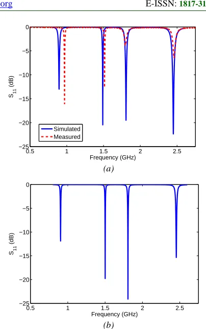
The simulated reflection coefficients for both antennas are shown in Figure 3. It can be noticed from the figure that the four resonant frequencies are 0.895, 1.49, 1.806, and 2.45 GHz. The corresponding reflection coefficients at these frequencies are -12.85, -20.47, -19.5, and -22.24 dB respectively. While for substrate 2 the frequencies are: 0.9040, 1.501, 1.806, and 2.453 GHz. The corresponding reflection coefficients are 11.89, -19.79, -24.12, and -15.35 dB. After optimization, it can be seen that the matching is very good at all resonant frequencies for both designs. The measured results of the antenna (substrate 1) are shown in Figure 3 (a). It can be seen that there is a slight shift in the resonant frequency for the first two bands and the matching is bad for the two upper bands, this may be due to the via position; it is very close to the excitation probe which makes it very difficult to solder, and it needs some facilities which are not available in our laboratory.
0.5 1 1.5 2 2.5
−25 −20 −15 −10 −5 0
Frequency (GHz)
S1
1
(dB)
Simulated Measured
(a)
0.5 1 1.5 2 2.5
−25 −20 −15 −10 −5 0
Frequency (GHz)
S1
1
(dB)
(b)
Figure 3: Reflection Coefficient of the Optimized Antenna (a) Substrate 1 and (b) Substrate 2.
4.
SURFACE CURRENT DENSITIES ANDRADIATION CHARACTERISTICS
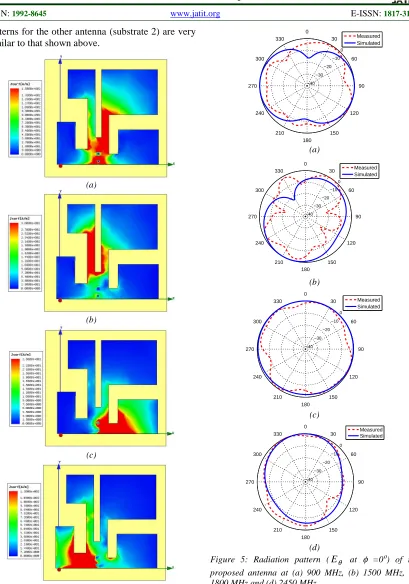
To understand the quad band operation, Figure 4 shows the surface current densities on the antenna at the four resonant frequencies. It can be seen from the figure that at the first resonance, the longest patch has a high current density, and this patch resonates at 900 MHz. Also, the shortest patch resonates at the higher frequency (2450 MHz). It’s clear from these plots that the proposed antenna operates at quad bands of frequencies, and the longer strip resonates at the lower frequency as expected.
The radiation patterns for the antenna at the four resonant frequencies are shown in Figures 5, 6 and 7. Figures 5 and 6 show the simulated and measured electric field Eθ in the x-z plane (φ =0ο)
[image:3.612.84.301.287.448.2]ISSN: 1992-8645 www.jatit.org E-ISSN: 1817-3195
patterns for the other antenna (substrate 2) are very similar to that shown above.
(a)
(b)
(c)
(d)
Figure 4: Surface current densities on the proposed antenna at (a) 900 MHz, (b) 1500 MHz, (c) 1800 MHz and (d) 2450 MHz.
0 −10 −20 −30 −40
0 30
60
90
120
150 180 210 240 270
300
330 Measured
Simulated
(a)
0 −10 −20 −30 −40
0 30
60
90
120
150 180 210 240 270
300
330 Measured
Simulated
(b)
0 −10 −20 −30 −40
0 30
60
90
120
150 180 210 240 270
300
330 Measured
Simulated
(c)
0 −10 −20 −30 −40
0 30
60
90
120
150 180 210 240 270
300
330 MeasuredSimulated
(d)
[image:4.612.103.512.68.652.2]ISSN: 1992-8645 www.jatit.org E-ISSN: 1817-3195
0 −10 −20 −30 −40 0 30 60 90 120 150 180 210 240 270 300 330 Measured Simulated (a) 0 −10 −20 −30 −40 0 30 60 90 120 150 180 210 240 270 300 330 Measured Simulated (b) 0 −10 −20 −30 −40 0 30 60 90 120 150 180 210 240 270 300 330 Measured Simulated (c) 0 −10 −20 −30 −40 0 30 60 90 120 150 180 210 240 270 300 330 Measured Simulated (d)
Figure 6: Radiation pattern (Eθ at φ =90ο) of the proposed antenna at (a) 900 MHz, (b) 1500 MHz, (c) 1800 MHz and (d) 2450 MHz.
The patterns in the x-y plane (θ =90ο) are shown in Figure 7. It is noticed from the figure that the patterns are omnidirectional at all resonant frequencies and there is a good agreement between simulated and measured results.
0 −10 −20 −30 −40 0 30 60 90 120 150 180 210 240 270 300 330 Measured Simulated (a) 0 −10 −20 −30 −40 0 30 60 90 120 150 180 210 240 270 300 330 Measured Simulated (b) 0 −10 −20 −30 −40 0 30 60 90 120 150 180 210 240 270 300 330 Measured Simulated (c) 0 −10 −20 −30 −40 0 30 60 90 120 150 180 210 240 270 300 330 Measured Simulated (d)
[image:5.612.91.514.69.621.2]ISSN: 1992-8645 www.jatit.org E-ISSN: 1817-3195
5.
CONCLUSIONA new quad-band small size microstrip handset antenna is designed and simulated for the GSM 900, GPS1500, DCS1800, and WLAN2450 frequency bands. Two different substrate materials are used. The overall antenna dimension for substrate 1 is 34 x 31.2 mm, while for substrate 2 it is 14.5 x 14 mm only. The antenna parameters are optimized to improve the matching at the four frequency bands. The antennas are simulated using HFSS software. Good results for the reflection coefficient are obtained. The surface current densities and radiation patterns at the four resonant frequencies are also shown to understand the operation of the antenna.
REFRENCES:
[1] C. R. Rowell, and R. D. Murch, "A compact PIFA suitable for dual-frequency 900/1800-MHz operation," IEEE Transaction on Antennas and Propagation, Vol. 46, Issue 4,
April 1998, pp. 596-598.
[2] C. Y. D. Sim, "A novel dual frequency PIFA design for ease of manufacturing," Journal of
Electromagnetic Waves and Applications, Vol.
21, No. 3, 2007, pp. 409-419.
[3] W. Geyi, Q. Rao, S. Ali, and D. Wang, "Handset antenna design: practice and theory,"
Progress In Electromagnetics Research, PIER
80, 2008, pp. 123-160.
[4] C. T. P. Song, P. S. Hall, H. Ghafouri-Shiraz, and D. Wake, "Triple band planar inverted F antennas for handheld devices," Electronics
Letters, Vol. 36, No. 2, 2000, pp. 112-114.
[5] F. R. Hsiaoand, and K. L. Wong, "Compact planar inverted-F patch antenna for triple-frequency operation," Microwave and Optical
Technology Letters, Vol. 33, June 2002, pp.
459-462.
[6] R. K. Raj, M. Joseph, B. Paul, and P. Mohanan, "Compact planar multiband antenna for GPS, DCS, 2.4/5.8 GHz WLAN applications," Vol. 41, Issue 6, 2005, pp. 290-291.
[7] W. Liao, S. Chang, and L. Li, " A compact planar multiband antenna for integrated mobile devices," Progress In Electromagnetics Research, PIER 109, 2010, pp. 1-16.
[8] R. Porath, "Theory of miniaturized shorting-post microstrip antennas," IEEE Transaction
on Antennas and Propagation, Vol. 48, 2000,
pp. 41–47.
[9] Y. Chow, K. Wan, "Miniaturizing patch antenna by adding a shorting pin near the feed probe - a folded monopole equivalent," IEEE Antennas
and Propagation Society International
Symposium, Vol. 4, 2002, pp. 4-9.
[10] G. Kumar and K.P. Ray, “Broadband Microstrip Antennas,” Artech House, Inc., 2003.
[11] C.R. Rowell and R.D. Murch, "A compact PIFA suitable for dual frequency 900/1800-MHz operation," IEEE Transaction on Antennas and Propagation, Vol. 46, 1998, pp.
596–598.
[12] Z.D. Liu, P.S. Hall, and D. Wake, "Dual-frequency planar inverted-F antenna," IEEE
Transaction on Antennas and Propagation,
Vol. 45, 1997, pp. 1451–1458.
[13] M. A. S. Alkanhal, "Composite compact triple-band microstrip antennas," Progress In
Electromagnetics Research, PIER 93, 2009,
pp. 221-236.
[14] HFSS: High Frequency Structure Simulator
Based on Finite Element Method, v. 11.0.2,
![Table 1: Calculated Dimensions Using Theory in [13] (mm)](https://thumb-us.123doks.com/thumbv2/123dok_us/8913872.960726/2.612.317.509.405.688/table-calculated-dimensions-using-theory-mm.webp)