Feed Forward Artificial Neural Network Based
Modelling of SVC & Wind Farm System
Ashwani Kumar1
1
Department of Electrical Engineering, Mewar University
Abstract: The concept of Var compensation embraces a wide and diverse field of both system and customer problems, especially related with power quality issues, since most power quality problems can be attenuated or solved with an adequate control of reactive power. In general, the problem of reactive power compensation is viewed from two aspects: load compensation and voltage support. Static voltage instability is mainly associated with reactive power imbalance. Thus, the load ability of a bus in a system depends on the reactive power support that the bus can receive from the system. As the system approaches the maximum loading point or voltage collapse point, both real and reactive power losses increase rapidly. Therefore, the reactive power supports must be locally adequate. With static voltage stability, slowly developing changes in the power system occur that eventually lead to a shortage of reactive power and declining voltage. The Flexible AC Transmission System (FACTS) technology is a promising technology to achieve complete deregulation of power system based on power electronic devices, used to enhance the existing transmission capabilities in order to make the system flexible and independent in operation then the system will be kept within limits without affecting the stability. Increased transmission demand is met where possible by increasing the existing transmission capacity. When trying to improve the transmission capacity, a key assumption is made that if the overall system reliability is not improved, at least the existing system reliability is maintained. The research work in this thesis is focused on FACT’S Controllers and Artificial Neural Network. Concept of Artificial Neural Network is described in detail. In this paper, it is presented how a Feed-Forward Neural Network is trained through MATLAB Programs using a set of input values of a parameter obtained through running of developed simulations of FACTS Controllers in MATLAB/SIMULINK. Keywords: Feed forward neural network, artificial neural network, Static Var compensator, Flexible AC transmission, FACTS controller
I. INTRODUCTION
The worldwide concern about environmental pollution and a possible energy shortage has led to increasing interest in technologies for the generation of renewable electrical energy. Among various renewable energy sources, wind power is the most rapidly growing one in Europe and the United States. With the recent progress in modern power electronics, the concept of a variable-speed wind turbine (VSWT) equipped with a doubly fed induction generator (DFIG) is receiving increasing attention because of its advantages over other wind turbine generator concepts. In the DFIG concept, the induction generator is grid-connected at the stator terminals; the rotor is connected to the utility grid via a partially rated variable frequency ac/dc/ac converter (VFC), which only needs to handle a fraction (25%–30%) of the total DFIG power to achieve full control of the generator. The VFC consists of a rotor-side converter (RSC) and a grid-rotor-side converter (GSC) connected back-to-back by a dc-link capacitor. When connected to the grid and during a grid fault, the RSC of the DFIG may be blocked to protect it from over current in the rotor circuit. The wind turbine typically trips shortly after the converter has blocked and automatically reconnects to the power network after the fault has cleared and the normal operation has been restored.
II. STATICVARCOMPENSATOR-SVC
The SVC has been used for reactive power compensation since the mid1970, firstly for arc furnace flicker compensation and then in power transmission systems. One of the first 40 MVAR SVC was installed at the Shannon Substation of the Minnesota Power and Light system in 1978. The SVC results in the following benefits:
A. Voltage support, and regulation, B. Transient stability improvement, and C. Power system oscillation damping, D. Reactive power compensation,
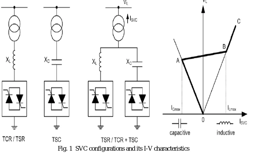
Fig. 1 shows these configurations: Thyristor Controlled Reactor (TCR), Thyristor Switched Reactor (TSR) and Thyristor Switched Capacitor (TSC) or a combination of all three in parallel configurations. The TCR uses firing angle control to continuously increase/decrease the inductive current whereas in the TSR the inductors connected are switched in and out stepwise, thus with no continuous control of firing angle.
[image:3.612.106.518.159.408.2]Usually SVC’s are connected to the transmission lines, thus having high voltage ratings. Therefore, the SVC systems have a modular design with more thyristor valves connected in series/ parallel for extended voltage level capability.
Fig. 1 SVC configurations and its I-V characteristics
III. REACTIVEPOWERCOMPENSATION
response times play an important role, allowing to increase the amount of apparent power transfer through an existing line, close to its thermal capacity, without compromising its stability limits.
IV.ARTIFICIALNEURALNETWORK
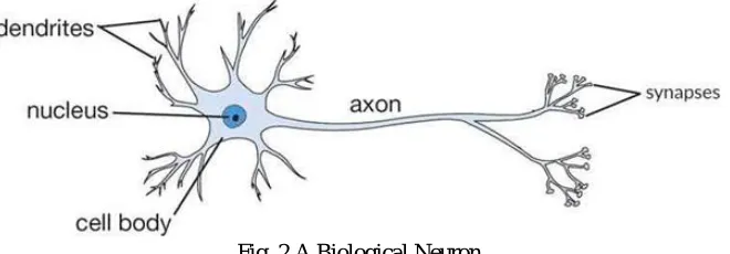
[image:4.612.144.474.269.384.2]An Artificial Neural Network (ANN) is an information processing paradigm that is inspired by the way biological nervous systems, such as the brain, process information. The key element of this paradigm is the novel structure of the information processing system. It is composed of many highly interconnected processing elements (neurons) working in unison to solve specific problems. ANNs, like people, learn by example. An ANN is configured for a specific application, such as pattern recognition or data classification, through a learning process. Learning in biological systems involves adjustments to the synaptic connections that exist between the neurons. This is true in case of ANNs as well. The basic building block of all biological brains is a nerve cell, or a neuron as shown in the Fig.2. Each neuron acts as a simplified numerical processing unit. In essence, the brain is a bundle of many billions of these biological processing units, all heavily interconnected and operating in parallel. In the brain, each neuron takes several input values from other neurons, applies a transfer function and sends its output on to the next layer of these neurons. These neurons in turn send their output to the other layers of neurons in a cascading fashion [14].
Fig. 2 A Biological Neuron
In similar manner, ANNs are usually formed from many hundreds or thousands of simple processing units, connected in parallel and feeding forward in several layers. In a biological neural network, the memory is believed to be stored in the strength of interconnections between the layers of neurons. Using neural network terminology, the strength or influence of an interconnection is known as its weight. ANN borrows from this theory and utilizes variable interconnections weights between layers of simulated neurons. ANNs were proposed early in 1960’s, but they received little attention until mid-80’s. Prior to that time, it was not generally possible to train networks having more than two layers. These early two layers networks were usually limited to expressing linear relationships between binary input and output characters. Unfortunately, the real world is analog and doesn’t lend itself to a simple binary model. The real innovation in ANN research came with the discovery of the backpropagation method. Because of fast and inexpensive personal computers availability, the interest in ANNs has blossomed. The basic motive of the development of the neural network was to make the computers to do the things, which a human being cannot do. Therefore, ANN is an attempt to simulate a human brain. Hence, the ANN architecture can be easily compared with the human brain. An artificial neural network is a system based on the operation of biological neural networks, in other words, is an emulation of biological neural system.
A. Advantages
1) A neural network can perform tasks that a linear program can not.
2) When an element of the neural network fails, it can continue without any problem by their parallel nature 3) A neural network learns and does not need to be reprogrammed.
4) It can be implemented in any application. 5) It can be implemented without any problem.
B. Disadvantages
1) The neural network needs training to operate.
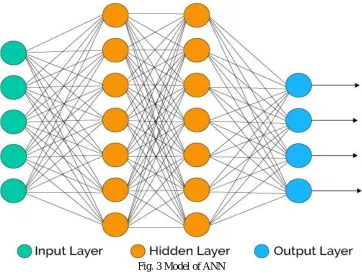
Fig. 3 Model of ANN
C. Model of Artificial Neural Network
The model of Artificial neural network is shown in fig. 3, which has input layer, hidden layer and output layer. The input layer contains those units (artificial neurons) which receive input from the outside world on which network will learn, recognize about or otherwise process. Output layer contains units that respond to the information about how it’s learned any task. Hidden layers are in between input and output layers. The job of hidden layer is to transform the input into something that output unit can use in some way. Most neural networks are fully connected that means to say each hidden neuron is fully connected to every neuron in its previous layer(input) and to the next layer (output) layer.The neuron has following parts:
1) Neuron: A neuron (or cell or a unit) is an autonomous processing element. Neuron can be thought of a very simple computer. The purpose of each neuron is to receive information from other neurons, perform relatively simple processing of the combined information, and send the results to one or more other neurons. Generally, neurons are represented by circle or squares.
2) Layers: A layer is a collection of neurons that can be thought of as performing some type of common functions. These neurons are usually numbered by placing the numbers or letters by each neuron and are generally assumed that no neuron is connected to another neuron in the same layer.
3) Synapses: An arc or a synapse can be a one-way or a two-way communication link between two cells as shown in the Fig. 2. A feed-forward network is one in which the information flows from the input cells through hidden layers to the output neurons without any paths whereby a neuron in a lower numbered layer receives input from the neurons in a high numbered layer. A recurrent network, by contrast, also permits communication in the backward direction.
4) Weights: A weight wij is a real number that indicates the influence that neuron ni has on neuron nj. For example, positive weights indicate reinforcement, negative weights indicate inhibition and a weight zero (or the absence of weight) indicates that no direct influence or connection exists.
5) Propagation Rule: A propagation rule is a network rule that applies to all the neurons and specifies how outputs from cells are combined into an overall net input to neuron n. The term ‘net’, indicates this combination. The most common rule is the weighed sum rule wherein, adding the products of the inputs and their corresponding weights forms the sum,
net i = bi+ Σ wij nij
V. PROBLEMFORMULATION
The training algorithm of back propagation involves four stages [14], viz. A. Initialization of Weights
B. Feed Forward
C. Back Propagation of errors
D. Updation of the weights and the biases.
During first stage which is the initialization of weights, some small random values are assigned. During feed forward stage each input unit (xi) receives an input signal and transmits this signal to each of the hidden units z1………zp. Each hidden unit then calculates the activation function and sends its signal zj to each output unit. The output unit calculates the activation function to form the response of the net for the given input pattern.
During back propagation of errors, each output unit compares its computed activation yk with its target value tk to determine the
associated error for that pattern with that unit. Based on the error, the factor δk is computed and is used to distribute the error at output unit ykback to all units in the previous layer. Similarly factor δj is computed for each hidden unit zj.
During final stage, the weight and biases are updated using the δ factor and the activation,
x: inzput training vector x: (x1, ………. xi, …., xn) t: Output target vector t: (t1, ………. ti, tn)
δk =error at output unit yk
δj =error at hidden unit zj
ά= learning rate
Voj= bias on hidden unit j zj= hidden unit j
wok=bias on output unit k yk= output unit k
The training algorithm used in the back-propagation network is as follows. The algorithm is given with the various phases: 1) Initialization of Weights
[image:6.612.150.448.476.710.2]Step 1: Initialize weight to small random values. Step 2: While stopping condition is false, do Steps 3-10. Step 3: For each training pair do steps 4-9.
2) Feed Forward
Step 4: Each input unit receives the input signal xi and transmits this signals to all units in the layer above i.e hidden units.
Step 5: Each hidden unit ( zj, j=1,……,p) sums its weighted input signals.
z-inj=voj+Σxivij (3.1) applying activation function
zj=f(zinj) (3.2) and sends this signal to all units in the layer above i.e. output units.
Step 6: Each output unit (yk) sums its weighted input signals.
y-ink=wok+Σzjwjk (3.3) and applies its activation function to calculate the output signals.
yk=f(y-ink) (3.4)
3) Back Propagation of Errors
Step 7: Each output unit receives a target pattern corresponding to an input pattern, error information term is calculated as
δk =(tk-yk)f(y-ink) (3.5) Step 8: Each hidden unit (zj) sums its delta inputs from units in the layer above
δ-inj = Σ δj wjk (3.6) The error information term is calculated as
δj =δ-inj f(z-inj) (3.7) 4) Updation of Weight and Biases
Step 9: Each output unit (yk) updates its bias and weights (j=0, …., p). The weight correction term is given by: ΔWjk= ά δk zj (3.8) and the bias correction term is given by
ΔWok= ά δk (3.9) Wjk(new)=Wjk(old)+ΔWjk , Wok(new)=Wok(old)+ ΔWok (3.10)
Each hidden unit (zj,j=1,…….p) updates its bias and weights (i=0,…..n) The weight correction term
ΔVij= ά δj xi (3.11) The bias correction term
ΔVoj= ά δj (3.12) Therefore, Vij(new)= Vij (old) + ΔVij , Voj(new)= Voj (old) + ΔVoj (3.13) Step 10: Test the stopping condition.
The stopping condition may be the minimization of the errors, number of epochs etc.
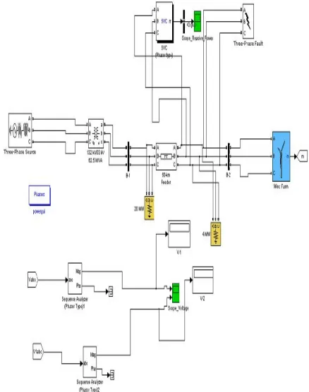
VI. SIMULATIONANDMODELLING
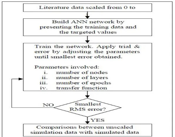
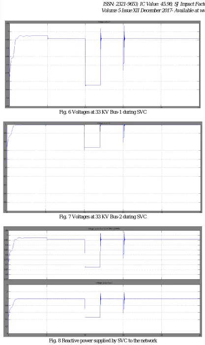
shows the voltage at 33 KV at bus 1 during static voltage control. Figure 7 shows the voltage at 33 KV at bus 2 during SVC. Figure 8 shows the Reactive power supplied by SVC to the network. Results are presented in table 1, which shows the Values of voltage at bus 1 and 2 and Reactive power by SVC between 1 to 20 s. The results obtained are voltages V1 and V2 and the reactive power. The reactive power at bus 1 for the different time period is obtained. Table 2 shows the comparison of voltage values on Bus 1 and 2, the results have been obtained by simulation using MATLAB and through Artificial Neural Network.
Fig. 6 Voltages at 33 KV Bus-1 during SVC
Fig. 7 Voltages at 33 KV Bus-2 during SVC
[image:9.612.105.508.493.719.2]TABLE I
VALUES OF VOLTAGE AT BUS 1 AND 2 AND REACTIVE POWER BY SVC BETWEEN 1 TO 20S
Time (s) V1 (p.u.) V2 (p.u.)
Reactive Power by SVC (MVAR)
1 .9265 .9663 -1.501
2 .9379 .9752 -.8471
3 .9378 .9737 -.8373
4 .9373 .9732 -.8702
5 .9377 .9728 -.8815
6 .9213 .9769 -.7522
7 .9213 .9769 -.7522
8 .9213 .9769 -.7522
9 .9213 .9769 -.7522
10 .9213 .9769 -.7522
10.125 .8491 1.0 -3.861
10.150 .8491 1.0 -3.861
10.199 .8491 1.0 -3.861
10.2 .9196 .9727 -.6692
10.3 .9213 .9769 -.7522
10.5 .9213 .9769 -.7522
11 .9213 .9769 -.7522
12 .9213 .9769 -.7522
13 .9213 .9769 -.7522
14 .9213 .9769 -.7522
15 .9213 .9769 -.7522
17 .9213 .9769 -.7522
18 .9213 .9769 -.7522
19 .9213 .9768 -.7524
20 .9209 .9759 -.7498
TABLE III
VALUES OF VOLTAGE ON BUS 1 AND BUS 2 OBTAINED THROUGH MATLAB/SIMULINK AND THROUGH NEURAL NETWORK
VII. CONCLUSIONANDFUTURESCOPEOFWORK
For the proposed work stability improvement of wind generation system using induction generators is investigated. The wind farms supply the active power to the grid when the wind turbines are connected to the grid, but at the same time, the reactive power is absorbed from grid. Induction machines are mostly used as generators in wind power based generations. Induction generators draw reactive power from the system to which they are connected, which is undesirable for the transmission system. Particularly in the
Sr. No.
Value of Load L1 and L2
(MW)
Time (s)
Voltage at Bus 1and Bus 2 obtained through SIMULINK (p.u)
Voltage at Bus 1and Bus2 obtained through ANN (p.u)
Error (%)
1 L1=20, L2=4 5 .9458 .9904 .9558 .9507 -1.05 4
2 L1=20 , L2= 4 10 .9272 .9916 .9360 .9420 -.9 5
3 L1= 20 , L2=
4 15 .9272 .9916 .9360 .9420 -0.94 5
4 L1= 15 , L2=
6 5 .9616 .9914 .9611 .9554 .05 3.63
5 L1= 15 , L2=
6 10 .9432 .9918 .9415 .9475 .180 4.46
6 L1=15 , L2=
6 15 .9432 .9918 .94155 .9475 .18 4.46
7 L1= 40 , L2=
10 5 .8163 .9512 .81882 .5162 -.30 4.57
8 L1= 40 , L2=
10 10 .7078 .8435 .7104 .4692 -.36 44
9 L1= 40 , L2=
10 15 .7078 .8435 .7104 .4692 -.36 44
10 L1= 4 , L2=
case of large turbines and weak distribution system. Without reactive power compensation, the integration of wind power in a network causes voltage collapse in the system and under-voltage tripping of wind power generators. Therefore, it is necessary to compensate the reactive power for grid-connected wind farm to eliminate the effects of voltage fluctuations which is caused by reactive power loss in grid. With the rapid development of power electronics technology, traditional reactive power compensation shows some obvious drawbacks and connecting the Flexible AC Transmission System (FACTS). Static Var Compensator (SVC) is proposed in this study to compensate the reactive power & improve the stability of the system. An additional active voltage support produced by a SVC can significantly improve the recovery of wind turbines from the fault due to faster restoration of the voltage, improving the stability of the induction generator. Since some other FACT Controllers are cheaper than SVC for the same rating, it is desirable to study the effect of other FACTS in a wind energy system.
REFERENCES
[1] Global wind report annual market update 2012 by GWEC (Global Wind Energy Council).
[2] Valarmathi, R. and A. Chilambuchelvan “Power Quality Analysis in 6 MW Wind Turbine Using Static Synchronous Compensator”, American Journal of Applied Sciences 9 (1): 111-116, 2012 ISSN 1546-9239 © 2012 Science Publications.
[3] M. Tarafdar Hagh, A. Roshan Milani, A. Lafzi," Dynamic Stability Improvement of a Wind Farm Connected to Grid Using STATCOM”, 2008 IEEE. [4] Z. Chen, Y. Hu, and F. Blaabjerg, “Stability improvement of induction wind turbine systems”, 2006 IEEE.
[5] G. Elsady, Y. A. Mobarak, and A-R Youssef “STATCOM for Improved Dynamic Performance of Wind Farms in Power Grid”, Proceedings of the 14th International Middle East Power Systems Conference (MEPCON’10), Cairo University, Egypt, December 19-21, 2010, Paper ID 207.
[6] Z. Chen, Y. Hu, “STATCOM’s effects on stability improvement of induction generator based wind turbine systems” 2009 IEEE.
[7] S. M. Shinde, K. D. Patil, and W. Z. Gandhare “Dynamic Compensation of Reactive Power for Integration of Wind Power in a Weak Distribution Network”, INTERNATIONAL CONFERENCE ON “CONTROL, AUTOMATION, COMMUNICATION AND ENERGY CONSERVATION -2009, 4th-6th June 2009 [8] Dipesh. M. Patel, A. R. Nagera, and Dattesh Y. Joshi “Power Quality Improvement with Static Compensator on Grid Integration of Wind Energy System”
INSTITUTE OF TECHNOLOGY, NIRMA UNIVERSITY, AHMEDABAD – 382 481, 08-10 DECEMBER, 2011.
[9] Amit Garg and Sanjai Kumar Agarwal “voltage control and dynamic performance of power transmission system using statcom and its comparison with svc”, International Journal of Advances in Engineering & Technology, Jan 2012.
[10] Bijaya Pokharel and Wenzhong Gao “Mitigation of Disturbances in DFIG-based Wind Farm Connected to Weak Distribution System Using STATCOM” North American Power Symposium (NAPS), 2010.
[11] Wang Xiao ming, Mu xing xing “Simulation Study on Dynamic Reactive Power Compensation of Grid-Connected Wind Farms”, Proceedings of the 2012 2nd International Conference on Computer and Information Application (ICCIA 2012).
[12] Ali Ozturk, Kenan Dosoglu “Investigation of the control voltage and reactive power in wind farm load bus by statcom and svc” Duzce University, Duzce, Turkey.
[13] Sharad W. Mohod, Member, IEEE, and Mohan V. Aware “A STATCOM -Control Scheme for Grid Connected Wind Energy System for Power Quality Improvement“ IEEE SYSTEMS JOURNAL, VOL. 4, NO. 3, SEPTEMBER 2010.
[14] Lie Xu, Liangzhong Yao, and Christian Sasse “Comparison of Using SVC and STATCOM for Wind Farm Integration”, 2006 International Conference on Power System Technology.
[15] Amit Garg, Ravindra Pratap Singh “Dynamic Performance Analysis of IG based Wind Farm with STATCOM and SVC in MATLAB / SIMULINK”, International Journal of Computer Applications (0975 – 8887) Volume 71– No.23, June 2013.
[16] Raimonds Cimbals, Oskars Krievs, Leonids Ribickis “A Static Synchronous Compensator for Reactive Power Compensation under Distorted Mains Voltage Conditions”, 10th International Symposium “Topical Problems in the Field of Electrical and Power Engineering” Pärnu, Estonia, January 10-15, 2011. [17] Bhim Singh, S. S. Murthy and Sushma Gupta “Analysis and Design of STATCOM-Based Voltage Regulator for Self-Excited Induction Generators”, IEEE
TRANSACTIONS ON ENERGY CONVERSION, VOL. 19, NO. 4, DECEMBER 2004.
[18] Bindeshwar Singh “Introduction to FACTS Controllers in Wind Power Farms: A Technological Review”, INTERNATIONAL JOURNAL OF RENEWABLE ENERGY RESEARCH Bindeshwar Singh, Vol.2, No.2, 2012.
[19] K. MALARVIZHI, K. BASKARAN “Enhancement of Voltage Stability in Fixed Speed Wind Energy Conversion Systems using FACTS Controller”, International Journal of Engineering Science and Technology Vol. 2(6), 2010.
[20] Refdinal Nazir “modeling and simulation of an induction generator-driven micro/pyco hydro power connected to grid system”, Proceedings of the International Conference on Electrical Engineering and Informatics Institute Teknologi Bandung, Indonesia June 17-19, 2007.
[21] Arrik Khanna, Sirdeep Singh “Integration of wind farm in power system using STATCOM”, International Journal of Scientific & Engineering Research, Volume 4, Issue 4, April-2013 ISSN 2229-5518.
[22] Ce Zheng, and Mladen Kezunovic, “Distribution System Voltage Stability Analysis with Wind Farms Integration”, Department of Electrical and Computer Engineering, Texas A&M University, College Station, TX 77840 USA.
[23] Guidelines for design of wind turbine, 2002 Det Norske Veritas and Riso National Laboratory; ISBN 87-550-2870-5, pp. 1-9. [24] Texas Comptroller of Public Accounts, “the energy report 2009”, Ch-11, May 2008, pp. 15.
[25] Global wind energy council, “Indian wind energy outlook 2012”, Nov 2012. [26] Wikipedia, the free encyclopedia.
[27] Olimpo Anaya-Lara, Nick Jenkine, “wind energy generation”, @2009 John Wiley & sons. Ltd, pp.1-16.
[28] Principle for efficient and reliable reactive power supply and consumption by Federal Energy Regulatory Commission.
[30] Raimonds Cimbals, Oskars Krievs, Leonids Ribickis “A Static Synchronous Compensator for Reactive Power Compensation under Distorted Mains Voltage Conditions”, 10th International Symposium “Topical Problems in the Field of Electrical and Power Engineering” Pärnu, Estonia, January 10-15, 2011. [31] Bhim Singh, S. S. Murthy and Sushma Gupta “Analysis and Design of STATCOM-Based Voltage Regulator for Self-Excited Induction Generators”, IEEE
TRANSACTIONS ON ENERGY CONVERSION, VOL. 19, NO. 4, DECEMBER 2004.
[32] Bindeshwar Singh “Introduction to FACTS Controllers in Wind Power Farms: A Technological Review”, INTERNATIONAL JOURNAL OF RENEWABLE ENERGY RESEARCH Bindeshwar Singh, Vol.2, No.2, 2012.
[33] K. MALARVIZHI, K.BASKARAN “Enhancement of Voltage Stability in Fixed Speed Wind Energy Conversion Systems using FACTS Controller”, International Journal of Engineering Science and Technology Vol. 2(6), 2010.
[34] Refdinal Nazir “modelling and simulation of an induction generator-driven micro/pyco hydro power connected to grid system”, Proceedings of the International Conference on Electrical Engineering and Informatics Institute Teknologi Bandung, Indonesia June 17-19, 2007.
[35] Arrik Khanna, Sirdeep Singh “ Integration of wind farm in power system using STATCOM”, International Journal of Scientific & Engineering Research, Volume 4, Issue 4, April-2013 ISSN 2229-5518.
[36] Ce Zheng, and Mladen Kezunovic, “Distribution System Voltage Stability Analysis with Wind Farms Integration”, Department of Electrical and Computer Engineering, Texas A&M University, College Station, TX 77840 USA.
[37] Guidelines for design of wind turbine, 2002 Det Norske Veritas and Riso National Laboratory; ISBN 87-550-2870-5, pp. 1-9. Texas Comptroller of Public Accounts, “The Energy Report 2009”, Ch-11, May 2008, pp. 15.
[38] Naresh Acharya, “Facts and Figures about FACTS”, Training Workshop on FACTS Application AIT,EPSM, Energy, EPSM, Asian Institute of Technology, December 16, 2004.
[39] Guowen H U, Ming CHENG, and Guilong CAI, “Relation between Fundamental Frequency Equivalent Impedance and Resonant Point for Thyristor Controlled Series Compensation”, 30th Annual Conference IEEE Industrial Electronics Society, vol. 2, pp. 1128-1132, 2004.
[40] C. R. Fuerte-Esquivel, E. Acha, and H. Ambriz-PBrez, “A Thyristor Controlled Series Compensator Model for the Power Flow Solution of Practical Power Networks”, TEEE Transactions on Power Systems.vol. 15, no. 1, pp. 58- 64, February 2000.
[41] Geng juncheng, Tong luyuan, and Wang Zhonghong, and Ge Jun,“Mathematical Model for describing characteristics of TCSC”, IEEE 2002 PP- 14981-502 [42] L. F. W. de Souza, E. H. Watanabe, J . E. R. Alves, and L. A. S.Pilotto, “Thyristor and Gate Controlled Series Capacitors Comparison of Components
Rating”, IEEE, 2003, pp: 2542-2547.
[43] M. N. Moschakis, E. A. Leonidaki, N. D. Hatziargyriou,“Considerations for the Application of Thyristor Controlled Series Capacitors to Radial Power Distribution Circuits”, Paper accepted for presentation at 2003 IEEE, PowerTech Conference, June 23-26, Bologna, Italy.