Design and Simulation of Floating Point Adder,
Subtractor & 24-Bit Vedic Multiplier
Sayali A. Bawankar1, Prof. Girish. D. Korde2 1M-tech (VLSI), E&T Department, BDCOE, Sewagram
2
Assistant Professor (Sr. Scale), E&T Department, BDCOE, Sewagram
Abstract: Arithmetic is the basic operation in everyday life which includes operation such as addition, subtraction, multiplication. Floating point representation is based on IEEE standard 754. This paper proposes implementation of IEEE floating point (FP) multiplication, addition and subtraction with minimum time. Arithmetic on IEEE FP numbers imposes more challenges compared to fixed-point arithmetic. Floating point numbers are used in various applications such as medical imaging, radar, telecommunications Etc. The results are obtained using ISim (VHDL/Verilog) Simulator. Since multiplication dominates the execution time of most DSP algorithms, so there is a need of high speed multiplier. Higher throughput arithmetic operations are important to achieve the desired performance in many real-time signal and image processing applications. One of the key arithmetic operations in such applications is multiplication and the development of fast multiplier circuit has been a subject of interest over decades. Multiplier based on Vedic Mathematics is one of the fast and low power multiplier. The language used for programming is VHDL, and is Synthesized using Xilinx ISE14.5 Suite. The target device selected is vertex6 family.
Key Words: IEEE 754, VHDL, Xilinx ISE.
I. INTRODUCTION
Addition is the most complex operation in a floating-point unit and offers major delay while taking significant area. Over the years, the VLSI community has developed many floating point adder algorithms mainly aimed to reduce the overall latency. Floating-point addition is the most frequent floating-point operation and accounts for almost half of the scientific operation. Therefore, it is a fundamental component of math coprocessor, DSP processors, embedded arithmetic processors, and data processing units. These components demand high numerical stability and accuracy and hence are floating- point based. Floating-point addition is a costly operation in terms of hardware and timing as it needs different types of building blocks with variable latency. In floating-point addition implementations, latency is the overall performance bottleneck. A lot of work has been done to improve the overall latency of floating-point adders. Various algorithms and design approaches have been developed by the Very Large Scale Integrated (VLSI) circuit community. Multipliers are key components of many high performance systems such as microprocessors, DSP processors, various FIR filters, etc. A performance of a system is generally determined by the performance of the multiplier because the multiplier is generally the slowest element in the system. Since multiplication dominates the execution time of most DSP application so there is need of high speed multiplier. Hence increasing the speed and optimizing area of the multiplier is a major design issue. As a result, a whole spectrum of multipliers with different area speed constraints has been designed with fully parallel Multipliers at one end of the spectrum and fully serial multipliers at the other end. These multipliers have moderate performance in both area and speed. In DSP application binary floating point numbers multiplication is one of the basic functions. The IEEE 754 standard provides for many closely related formats. The Single precision consist of 32 bits, Double precision consist of 64 bits. The digital arithmetic operations are very important in the design of digital processors and application-specific systems. An arithmetic circuit plays an important role in digital systems with the vast development in the very large scale integration (VLSI) circuit technology; many complex circuits have become easily implementable today. Algorithms that are seemed to be impossible to implement now have attractive implementation possibilities for the future. This means that not only the conventional computer arithmetic methods, but also the unconventional ones are worth investigation in new designs. The motion of real numbers in mathematics is convenient for hand computations and formula manipulations. However, real numbers are not well-suited for general purpose computation, because their numeric representation as a string of digits expressed in say, base 10 can be very long or even infinitely long. Examples include pie, e, and 1/3. In practice, computers store numbers with finite precision [8]. Numbers and arithmetic used in scientific computation should meet a few general criteria
A level of standardization, or portability, is desirable–results obtained on one computer should closely match the results of the same computation on other computers.
An arithmetic circuit which performs digital arithmetic operations has many applications in digital coprocessors, application specific circuits, etc. Because of the advancements in the VLSI technology, many complex algorithms that appeared impractical to put into practice, have become easily realizable today with desired performance parameters so that new designs can be incorporated [11]. The standardized methods to represent floating point numbers have been instituted by the IEEE-754 standard through which the floating point operations can be carried out efficiently with modest storage requirements. An arithmetic unit is a part of computer processor (CPU) that carries out arithmetic operations on the operands in computer instructions words. Generally arithmetic unit performs arithmetic operations like addition, subtraction, multiplication, division. Some processor contains more than one AU - for example one for fixed operations and another for floating point operations. To represent very large or small values large range is required as the integer representations is no longer appropriate. These values can be represented using IEEE -754 Standard based floating point representation. In most modern general purpose computer architecture, one or more FPUs are integrated with the CPU; however many embedded processors, especially older designs, do not have hardware support for floating point operations. Almost every languages has a floating point data types; computers from pc’s to supercomputers have floating point accelerators; most compliers will be called upon to compile floating point algorithm from time to time; virtually every operating system must respond to floating point exceptions such as overflow [6].
A. Floating Point Number
The term floating point is derived from the meaning that there is no fixed number of digits before and after the decimal point, that is, the decimal point can float. There was also a representation in which the number of digits before and after the decimal point is set, called fixed-point representations. In general floating point representations are slower and less accurate than fixed-point representations, but they can handle a larger range of numbers. Floating Point Numbers are numbers that consist of a fractional part. For e.g. following numbers are the floating point numbers: 35, -112.5, ½, 4E-5 etc. Floating point arithmetic is considered a tough subject by many peoples. This is rather surprising because floating-point is found in computer systems. Almost every language supports a floating point data type. A number representation (called a numeral system in mathematics) specifies some way of storing a number that maybe encoded as a string of digits. In computing, floating point describes a system for numerical representation in which a string of digits (or bits) represents a rational number. The term floating point refers to the fact that the radix point (decimal point, or more commonly in computers, binary point) can "float"; that is, it can be placed anywhere relative to the significant digits of the number [7].
B. IEEE-754 Standards
IEEE-754 is a Floating point technical standard established by IEEE in 1985 and the most widely used standard for floating-point computation, followed by many hardware (CPU and FPU) and software implementations. The standard defines five basic formats, named using their base and the number of bits used to encode them. There are three binary floating-point formats (which can be encoded using 32, 64, or 128 bits) and two decimal floating-point formats (which can be encoded using 64 or 128 bits). The first two binary formats are the ‘Single Precision’ and ‘Double Precision’ formats of IEEE-754 1985, and the third is often called 'quad': The decimal formats are similarly often called 'double' and ‘quad’ [8].
1) Single Precision Format: The IEEE Single precision format uses 32 bit for representing floating point number. Most significant bit starts from the left exponent, and mantissa [6].That is divided into three subfields and storage layout for single precision is as shown in fig 1.
II. FLOATING POINT ADDER /SUBTRACTOR
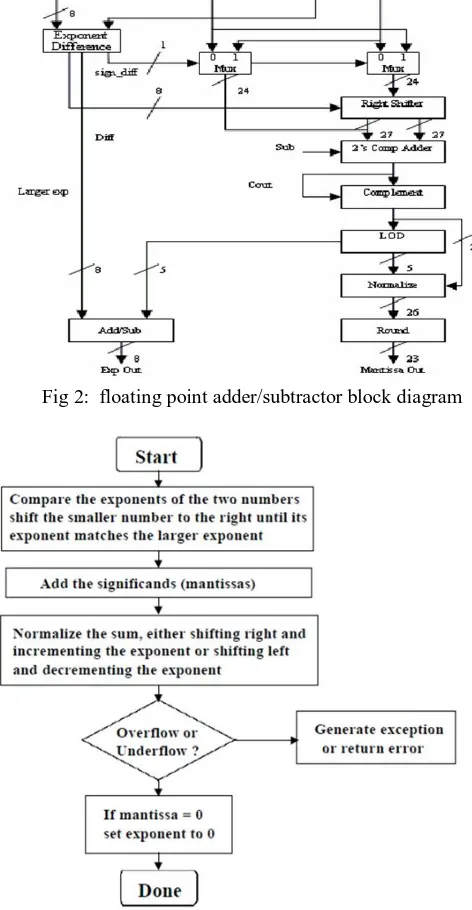
[image:4.612.184.424.226.425.2]Addition and subtraction are the most complex operations in a floating-point unit and offers major delay while taking significant area. Over the years, the VLSI community has developed many floating point adder algorithms mainly aimed to reduce the overall latency. Floating-point addition is the most frequent floating-point operation and accounts for almost half of the scientific operation. Therefore, it is a fundamental component of math coprocessor, DSP processors, embedded arithmetic processors, and data processing units. These components demand high numerical stability and accuracy and hence are floating- point based. Floating-point addition is a costly operation in terms of hardware and timing as it needs different types of building blocks with variable latency. In floating-point addition implementations, latency is the overall performance bottleneck. A lot of work has been done to improve the overall latency of floating-point adders. Various algorithms and design approaches have been developed by the Very Large Scale Integrated (VLSI) circuit community.
Fig 2: floating point adder/subtractor block diagram
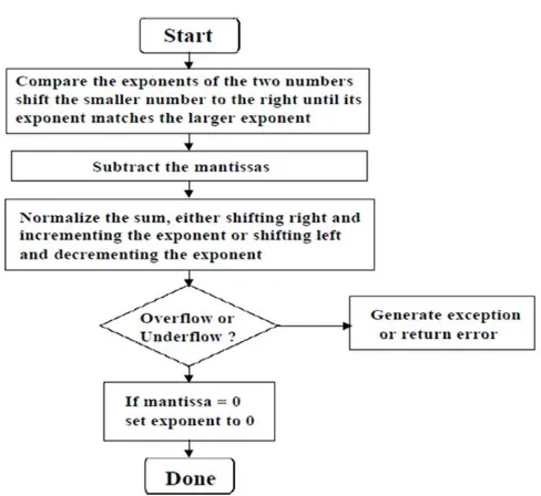
[image:4.612.180.416.235.690.2]Fig 4: Simplified floating point subtraction flowchart
III. 24* 24 VEDIC MULTIPLIER
The Vedic multiplication system is based on 16 Vedic sutras or aphorisms, which describes natural ways of solving a whole range of mathematical problems. Out of these 16 Vedic Sutras the Urdhva-triyakbhyam sutra is suitable for this purpose. In this method the partial products are generated simultaneously which itself reduces delay and makes this method fast. The method for multiplication of two, 3 BITs number. Consider the numbers A and B where A = a2a1a0 and B = b2b1b0. The LSB of A is multiplied with the LSB of B: s0=a0b0; Then a0 is multiplied with b1, and b0 is multiplied with a1 and the results are added together as: c1s1=a1b0+a0b1; Here c1 is carry and s1 is sum. Next step is to add c1 with the multiplication results of a0 with b2, a1 with b1 and a2 with b0. c2s2=c1+a2b0+a1b1 + a0b2; Next step is to add c3 with the multiplication results of a1 with b2 and a2 with b1. c3s3=c2+a1b2+a2b1; Similarly the last step c4s4=c3+a2b2; Now the final result of multiplication of A and B is c4s4s3s2s1s0.
A. Algorithm Steps
1) Multiplying the significant (1.M1*1.M2 )
2) Placing the decimal point in the result
3) Adding the exponents i.e.(E1 + E2 – Bias)
4) Obtaining the sign; i.e. s1 XOR s2
5) Normalizing the result; i.e. obtaining 1 at the MSB of the result’s significand
6) Checking for underflow/overflow occurrence
The result of the significant multiplication (intermediate product) must be normalized to have a leading „1‟ just to the left of the decimal
point (i.e. in the bit 46 in the intermediate product). Since the inputs are normalized numbers then the intermediate product has the leading one at bit 46 or 47
7) If the leading one is at bit 46 (i.e. to the left of the decimal point) then the intermediate product is already a normalized number and no shift is needed
8) If the leading one is at bit 47 then the intermediate product is shifted to the right and the exponent is incremented by 1.
normalized to 24 BIT by adding a 1 at MSB. The block diagram of 24x24 BIT multiplier is shown in Figure 5. This multiplier is modelled using structural style of modelling in VHDL. In this paper first a 3x3 Vedic multiplier is implemented using the above mentioned method. The 6x6 is designed using four 3x3 multipliers. After that the 12x12 is implemented using four 6x6 BIT multiplier. Finally the 24x24 BIT multiplier is made using four 12x12 BIT multipliers. The 24x24 BIT multiplier requires four 12x12 BIT multipliers and two 24 BIT ripple carry adders and 36 BIT ripple carry adders. A 24*24 Vedic multiplier is design by using four 12*12 Vedic multipliers based urdhva Triyakbhyam. Here first block 12X12 multiplier consists of lower 12 bits of x i.e. x(11 down to 0) and y(11 down to 0), second block 12*12 Vedic multiplier inputs are x(23 down to 12) and y(11 down to 0) out off 24 bit output of first block lower adder 12 bits are separated and higher order bits are appended as 12 lower bits in front augmented with “000000000000” now second block 24 bits and above 24 generate bits are added and 24 bits sum is generated using 24 bit ripple carry adder.
FIG 5:24*24 bit vedic multiplier block diagram
Higher order 12 bit of y(23 down to 12) and lower order 12 bits of x i.e x(11 down to 0) are multiplier and appended in front with “000000000000” to make 36 data similarly both higher order 12 bits of x and y i.e x(23 down to 12) and y(23 down to 12) are multiplier and 36 bit data is formed by appending “000000000000”. The above two 36 bits are added to generate a 36 bit data in the right side resultant 36 bits are added to generate final 36 bits the resultant of 24*24 multiplier is 48 bits consists of 36 higher bits from 36 bit adder output and lower order 12 bits 36+12=48 bits. The number of LUTs and slices required for the Vedic Multiplier is less and due to which the power consumption is reduced. Also the repetitive and regular structure of the multiplier makes it easier to design. And the time required for computing multiplication is less than the other multiplication techniques.
IV. IMPLEMENTATION ON XILINX SOFTWARE
[image:6.612.195.413.218.404.2]V. EXPERIMENTAL RESULT
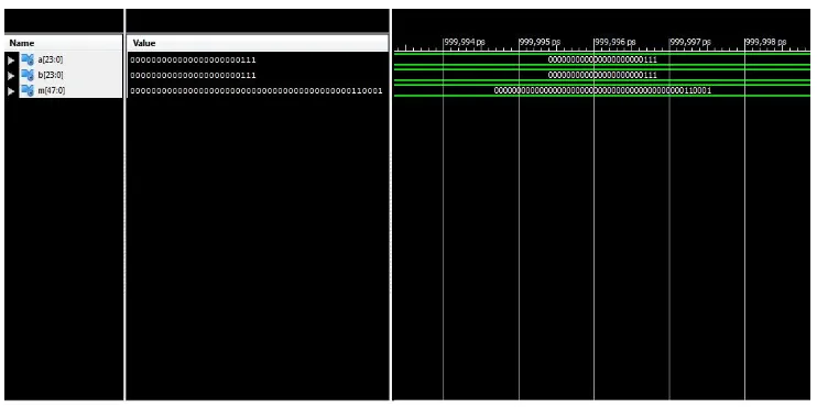
[image:7.612.121.494.132.291.2]The result of the 32*32 bit floating point adder, floating point subtractor and 24*24 bit vedic multiplier is given in the figures below in which 32-bit number is in binary form. Also the RTL schematic of 32*32 bit floating point adder, 32*32 bit floating point subtractor and 24*24 bit vedic multiplier is given.
Fig 6: simulation result of floating point adder
Fig 7: simulation result of floating point subtractor
[image:7.612.121.492.493.678.2]Fig 9: RTL schematic of floating point adder
[image:8.612.129.481.403.682.2]Fig 11: RTL schematic of floating point 24* 24 bit Vedic multiplier
VI. ACKNOWLEDGEMENT
we would like to thanks Mr. P. R. Indurkar, Associate Professor, Electronics and Telecommunication Department, B.D.C.O.E. for his valuable suggestion .we would thanks to our college for providing facilities which helps us in our research work. We also express thanks to our parents, friends and colleagues.
VII. CONCLUSION
The proposed is simulated using XILINX ISE 14.5. It was found that the multiplier based on Vedic sutras had execution delay of almost half of that of binary multiplier (partial products method). In proposed work, we will use floating point representation concept which have large range of values as well as accuracy and also we are using Vedic mathematics sutra. Hence hardware requirement is reduced, thereby reducing power consumption and delay. So, designing of power efficient 32-bit single precision Floating point adder, floating point subtractor and 24* 24 bit Vedic multiplier based on IEEE-754 standard using Vedic mathematics will be the probable outcome of this research work.
REFERENCES
[1] V. Vaibhav, K.V. Saicharan, B. Sravanthi, D. Srinivasulu “VHDL Implementation of floating point multiplier using Vedic mathematics”, International Conference on Electrical, Electronics and communications- ICEEC (2014).
[2] Sushma S. Mahakalkar, Sanjay L. Haridas “Design of High Performance IEEE754 Floating Point Multiplier Using Vedic mathematics”, 2014 Sixth International Conference on Computational Intelligence and Communication Network.
[3] Prof J M Rudagi, Vishwanath Ambli, Vishwanath Munavali, Ravindra Patil, Vinay kumar Sajjan “Design and implementation of Efficient multiplier using Vedic mathematics”, Proc. of 1nt. Con/, on Advances in Recent Technologies in Communication and Computing 2011
[4] Rupali Dhobale, Soni Chaturvedi, “FPGA Implementation of single precisions floating point adder”, International Journal of Innovative Research in Computer and Communication Engineering Vol. 3, Issue 6, June 2015
[5] Prerna Mandloi, Mr. Atush Jain, “VHDL Implementation of Addition and Subtraction unit for Floating Point Arithmetic Unit”, International Journal for Research in Technological Studies Vol. 1, Issue 10, September 2014 ISSN (online): 2348-1439
[6] Somsubhra Ghosh, Prarthana Bhattacharyya and Arka dutta, “FPGA Based implementation of a double precision IEEE Floating point adder”, seventh international conference on intelligent system and control (ISCO) @2012 IEEE
[7] Onkar singh, Kanika sharma “Design and implementation of area efficient single precision floating point unit”, IOSR journal of electronics and communication engineering (IOSR-JECE) Jan 201
[8] Shilpa Kukati, Sujana D.V, Shruti Udaykumar, Jayakrishnan “Design and implementation of low power floating point arithmetic unit “,2013 international conference on green computing, communication and conservation of energy(ICGCE)
[9] Mr. Anjana Sasidharan, Mr. P. Nagarajan “VHDL Implementation of IEEE 754 floating point unit”, ISBN No.978-1-4799-38346/14/$31.00 @ 2014 IEEE [10] Miss Pradnya A. Shengale, Prof Vidya Dahake, Prof Mithilesh Mahendra “Single Precision Floating point unit”, IRJET Volume:02 issue:02 May-2015 [11] Prashanth B.U. V, Anil Kumar, G. Sreenivasulu “Design and Implementation of Floating Point ALU on a FPGA Processor”, International Conferences on
Computing, Electronics and Electrical Technologies (ICCEET) 2012 IEEE