N A N O I D E A
Open Access
Spin accumulation assisted by the
Aharonov-Bohm-Fano effect of quantum
dot structures
Wei-Jiang Gong
1,3*, Yu Han
2, Guo-Zhu Wei
1,3and An Du
1Abstract
We investigate the spin accumulations of Aharonov-Bohm interferometers with embedded quantum dots by considering spin bias in the leads. It is found that regardless of the interferometer configurations, the spin accumulations are closely determined by their quantum interference features. This is mainly manifested in the dependence of spin accumulations on the threaded magnetic flux and the nonresonant transmission process. Namely, the Aharonov-Bohm-Fano effect is a necessary condition to achieve the spin accumulation in the quantum dot of the resonant channel. Further analysis showed that in the double-dot interferometer, the spin accumulation can be detailedly manipulated. The spin accumulation properties of such structures offer a new scheme of spin manipulation. When the intradot Coulomb interactions are taken into account, we find that the electron interactions are advantageous to the spin accumulation in the resonant channel.
Keywords: Spin accumulations, Aharonov-Bohm-Fano effect, quantum dot, Coulomb interaction
PAC Codes: 73.63.Kv, 71.70.Ej, 72.25.-b
Background
Quantum dot (QD), especially coupled-QD system (i.e., the QD molecule), is of fundamental interest in physics and possesses potential applications, such as quantum logic gates[1,2]. As a result, many experimental and theoretical works have paid so much attention to the electron transport properties of various multi-QD sys-tems in the past decades [3-10]. Besides, the progress of nanotechnology enables researchers to fabricate a variety of coupled-QD structures with sizes smaller than the elec-tron coherence length [11]. This also accelerates the devel-opment of researches on the coupled-QD characteristics.
With respect to the coupled-QD structures, the typical one is Aharonov-Bohm (AB) interferometer with one QD or whose individual arm is of one QD, respectively [12-38]. In such kind of structure, the AB phase can adjust the quantum interference, leading to abundant interesting results. Kobayashi et al. performed significant work to
*Correspondence: [email protected]
1College of Sciences, Northeastern University, Shenyang, 110819, China 3International Centre for Materials Physics, Chinese Academy of Sciences, Shenyang, 110016, China
Full list of author information is available at the end of the article
study the quantum interferences in the AB interferom-eters with embedded QDs [18-20]. According to their conclusions, the Fano effect, which manifests itself in the asymmetric lineshape of the transport spectrum, can be observed in such structures by constructing nonres-onant and resnonres-onant channels for electron transmission. Moreover, they showed that the orientation of the Fano lineshape changes periodically with the magnetic flux. Due to this reason, in the AB interferometer with QDs, the AB-Fano interference attracted more attention and was further investigated [22,23]. On the other hand, lots of theoretical investigations about electron transport behaviors of the AB interferometer have been reported. It was found that the interplay between the AB-Fano effect and the other mechanisms, e.g., Kondo physics and the spin-orbit interaction, indeed causes many interesting phenomena [24-38].
Electron not only has a charge but also spins with s= 12; accordingly, the electron spin in the QD has been suggested as an ideal candidate for the qubit. Then, the coherent generation and control of electron spins in QDs has recently become one main subject in spintronics [39-42]. Various schemes have been proposed: by
considering the spin transport and spin accumulation in QDs, based on the magnetic means, the spin-obit interaction, etc.[43-49]. Since in QD structures, the quan-tum interference contributes significantly to the electron motion properties, it is natural to question about the role of quantum interference on the spin accumulation. However, to our knowledge, little attention has been paid to such an issue so far. In this work, we choose the AB interferometer with embedded QDs and clarify the effect of a typical interference manner, i.e., the AB interference, on the spin manipulation in QDs. In doing so, we intro-duce a symmetric spin battery to the interferometer by considering the chemical potentials of the leads to be μLσ = εF + σeV2s and μRσ = εF + ¯σeV2s [50-54]. We intend to investigate the role of quantum interference in adjusting the spin-bias-induced spin accumulation. εF is the Fermi level of the system at the zero-spin-bias case, andVsis the magnitude of the spin bias. Due to the progress in experiment, such a scheme can be realized by injecting the charge current from a ferromagnetic source ( or a magnetic field ) into the leads of the QD structure [55-60]. Consequently, we find that to achieve the spin manipulation in the QDs of the AB interferometer, a finite magnetic flux and a nonresonant channel are prerequi-sites. Namely, the AB-Fano interference, not only the AB effect, is a necessary condition to realize the spin accu-mulation in the QDs. Also, the spin accuaccu-mulation can be adjusted by varying the quantum interference of the inter-ferometer. Therefore, we believe that such a structure is a promising candidate for spin manipulation.
Model and numerical results
The Hamiltonian that describes the electron motion in the AB interferometer can be written as
H=HL+HR+HD+HT. (1)
Hα (α = L,R) is the Hamiltonian in lead-α. HD is the Hamiltonian in the QDs, and the last term,HT, denotes electron traveling between the two leads. Hα takes a form as Hα = kσεαkσc†αkσcαkσ, where c†αkσ (cαkσ) is the creation (annihilation) operator corresponding to the basis in lead-α.εαkσ is the single-particle level. Since we investigate the electron properties of two AB interfer-ometers with one QD or two QDs, the expressions of HD andHT will be determined by the geometries of the interferometers.
The one-QD AB interferometer
We first focus on the AB interferometer of one QD, whose schematic is shown in Figure 1a. Then in such a case, HD=σεd†σdσ +Un↑n↓ and HT =kσ WLRc†LkσcRkσ +
αkσVαc †
αkσdσ + h.c..d †
σ(dσ) are the creation (annihilation) operator of electron in the QD,
andεis the energy level of QD.Uis the intradot electron interaction strength. WLR denotes the direct transmis-sion between the leads, andVα represents the coupling between the QD and lead-α.
The electron properties can be evaluated by using the nonequilibrium Green function technique. In the Green function space, the average electron occupation number of the QD is denoted as [61,62]
nσ = − i 2π
dωG<dd,σ(ω). (2)
G<is the lesser Green function, which can be obtained from the Dyson equation
G<(ω)=(1+rGr)g<(1+aGa)+Gr<Ga. (3)
GrandGaare the retarded and advanced Green functions, respectively. Due to the presence of electron interaction, the Green function is difficult to solve. However, if the sys-tem sys-temperature is higher than the Kondo sys-temperature, the electron interaction term can be included by using the Hubbard-I approximation [61-63]. In this work, we would like to consider the case of weak electron correla-tion; then, the retarded Green function can be analytically solved within the Hubbard-I approximation, i.e.,
[Grσ]−1=
⎡ ⎢ ⎢ ⎣
gLr−1 −WLR −VL −WLR∗ gRr−1 −VR −VL∗ −VR∗ gdr−σ1
⎤ ⎥ ⎥
⎦, (4)
where grα is the Green function of the isolated lead-α. Due to the continuum states in the leads, we write gαr = −iπρ(ω)with ρ(ω)being the density of states of the leads. grdσ, the Green function of the isolated QD, can be written as gdrσ = 1−nσ¯
ω−ε+i0+ +
nσ¯
ω−ε−U+i0+ in the Hubbard-I approximation. In this structure, G<dd,σ can be expressed as G<dd,σ = αGrdα,σgαr−1gασ<gαa−1Gaαd,σ, where gασ< = 2iπρ(ω)fασ(ω) is the lesser Green func-tion of the isolated lead-α with the Fermi distribu-tion funcdistribu-tion fασ(ω) =[ expω−μασ
kBT + 1]
−1. When the bandwidth of the leads is large enough, the density of states can be viewed as a constant. Accordingly, we have G<
dd,σ = πρ2i
α|Grdα,σ|2fασ(ω). As a result,nσcan be re-expressed as
nσ = 1
π2ρ
α
dω|Grdα,σ(ω)|2fασ(ω). (5)
Furthermore, by definingnc = σnσ andns = n↑ − n↓, we can investigate the features of the charge and spin in the QD.
-1.0 -0.5 0.0 0.5 1.0 1.5 -1.0
-0.5 0.0 0.5 1.0 1.5 2.0
s
c n n n n
↑
↓
s
c n n n n
↑
↓
(d)
(c)
ε
↓
↑ ↓
↑
L
Φ
R
LR
W
L
V VR
0.0 0.5 1.0 1.5 2.0 -1.0
-0.5 0.0 0.5 1.0
0.0 0.2 0.4 0.6 0.8 1.0 -1.0
-0.5 0.0 0.5 1.0 1.5 2.0
ε=0.0,W=0.3 ε=0.0,φ=0.5π eV
s=1.0 φ=0.5π W=0.3
W
φ
/
π
ε
s
c n n n n
↑
↓
[image:3.595.61.541.85.384.2](b)
(a)
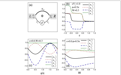
Figure 1The AB interferometer of one QD.(a)Schematic of an AB interferometer with an embedded QD.(b, c, d)The average electron occupation number and spin accumulation in QD affected by the structure parameters. The relevant parameters are taken to beρ=1,|Vα| =0.1, andeVs=1.0.
|Vα| = 0.1. In Figure 1b, it is observed that at the case ofφ = 0.5π, a spin-up electron can enter the QD only when the QD level decreases to the position ofε= −0.5. Instead, the QD is able to confine a spin-down electron ifε <0.5. By comparing the properties of opposite-spin electrons, we might as well consider that the spin-up and spin-down electrons are both in equilibrium, but they ‘feel’ the different ‘Fermi levels’, with the distance between them being the spin bias magnitude. Therefore, in such a structure, the striking spin accumulation can be realized in the QD. Next, in Figure 1c,d, by assumingε = 0, we present the influence of φ and W on the average occu-pation number of electron in the QD, respectively. It is observed that with the change of magnetic flux, the aver-age occupation of different-spin electrons show opposite variation features. Different from the result ofφ = 0.5π, when the magnetic flux is increased toφ =1.5π, the QD confines a spin-up electron. Then, the spin accumulation in the QD can be completely adjusted. Alternatively, with W increased toW = 0.3, the spin accumulation propor-tionally enhances; however, the further increase ofWwill lead to the suppression of spin accumulation.
Since the structure is relatively simple, we try to clarify the numerical result in an analytical way. Accordingly, we write out the expression ofGrdL,σby using
Equation 4, i.e.,GrdL,σ(ω)= D1 t[g
r
LWLRgRrVR+gLrVL] and GrdR,σ(ω)= D1
t[g r
RWLR∗ gLrVL + gRrVR] with Dt = gLrgRr det{[Grσ]−1}. When a local magnetic flux is applied, its effect on the quantum interference can be well defined by writingWLR=Weiφ. Here,Wis the strength of the lead-lead coupling, and the phase factorφ = φ
0 whereis the
magnetic flux with the magnetic flux quantumφ0 = hce. In the case of weak QD-lead coupling, e.g.,|Vα| = 0.1, the analytical form of nσ can be approximated as
nσ = −φ
L
L+RfLσ(ε)˜ +φ R
L+RfRσ(ε).˜ χ = πρW, ˜
ε=ε−2χ˜L˜Rcosφ,±φ = 1+χ
2±2χsinφ
1+χ2 , and˜α =
α
1+χ2 withα =π|Vα|2ρ. The expression ofncandns
can then be obtained, i.e.,nc =fα↑(ε)˜ +fα↓(ε)˜ andns =
−φ
L
L+R[fL↑(ε)˜ −fL↓(ε)]˜ +φ R
of ndσ andns can be simplified. For the example of πρW = 1 andφ = π2, nσ = L2+RRfRσ(ε) = fRσ(ε). Then, in such a case, the ‘Fermi level’ of the spin-σ elec-tron is at the point ofε = μRσ, leading to the result that ns = fR↑(ε) − fR↓(ε). Next, when the magnetic flux is raised to φ = 32π, there will bendσ = fLσ(ε)and ns =fL↑(ε)−fL↓(ε). The property of the spin polariza-tion is completely opposite to the case ofφ = π2. Based on such analysis, the spin accumulation in the QD is well understood.
The underlying physics being responsible for the above results is quantum interference. It is known that the inter-ference in the QD ring structure is rather complicated. However, in such a structure, the quantum interference that affects the spin accumulation just occurs between two Feynman paths. This is becauseGrdα,σ =τd(α1),σ+τd(2α),σ, where τdL(1),σ = ˜gdrσVR∗gRrWe−iφgr
L and τ (2)
dL,σ = ˜gdrσVL∗gLr withg˜drσ = 1+1χ2[ω− ˜ε+i(˜L+ ˜R)]−1. It is evident that
the phase difference between the two paths influences the magnitude of |Grdα,σ|2, hence changing the average electron occupation number in the QD. Via a simple calculation, the phase difference can be obtained, i.e., θdL,σ =[θR−φ] withθαbeing the argument ofgαr. Sim-ilarly, the two transmission paths between lead-Rand the QD can be given byτdR(1),σ = ˜gdrσVL∗gLrWeiφgRr andτdR(2),σ = ˜
gdrσVR∗gRr withθdR,σ =[θL +φ]. So, in the presence of finite magnetic flux, the amplitude of|GrdL,σ|2is different from that of|GrdR,σ|2. This leads to the different couplings between the QD and the leads. In the extreme case of πρW =1, the magnitudes ofτd(1α),σ andτd(2α),σare the same. Then, whenφ = π2, the destructive quantum interference betweenτdL(1),σandτdL(2),σcauses|GrdL,σ|2to be equal to zero, which leads to the decoupling of the QD from lead-L. However, the quantum interference between τdR(1),σ and τdR(2),σ is constructive sinceθdR,σ = 0 in such a case. So, the QD only feels lead-Rwithnσ = fRσ(ε). Oppositely, for the case ofφ = 32π, only the property of lead-L influ-ences the electron in the QD. So far, we have noted that the AB-Fano effect modulates the quantum interference that contributes to the electron distribution in the QDs.
In the following, we incorporate the electron interaction into the calculation. In the case of weak QD-lead coupling, nσcan be expressed in an analytical way, i.e.,
in whichFσ(ω)= −φLfLσ+φRfRσ L+R . Then,
In Figure 2, by assumingW =0.3 andφ = π2, we show the spin accumulation in the QD in the cases ofU = 0.5, 1.0, and 2.0, respectively. As shown in Figure 2a, for the cases ofU ≤eVs, the energy region where the spin accu-mulation emerges is directly widened, and in the whole region of −eVs
2 − U < ε < eVs
2 , the spin polarization is robust. Thus, the intradot Coulomb interaction bene-fits the spin accumulation in the QD. Such a result can be explained in the following way: Whenφ= π2, the QD only ‘couples to’ lead-Rin whichμR↓ = eV2s andμR↑ = −eV2s. Consequently, when the QD levelεis shifted belowμR↓, a spin-down electron will occupy such a level, but at this time, the levelε+Uis unoccupied. Next, when the level ε+U is belowμR↓, the Pauli exclusion principle makes it empty, so the spin accumulation in the QD is equal to −1 approximately. Only when the levelε+Udecreases to the position of μR↑ does a spin-up electron have an opportunity to occupy it, and then, the spin accumulation disappears. However, with regard to the case ofU = 2.0, we see that with the decrease ofεto−0.5, the magnitude of spin accumulation goes down deeply, and around the region ofε= −1.0, the value ofnsalmost encounters its zero. However, by a further adjustment ofε0toε0= −1.5, such a spin accumulation then gets close to 1 again. We can understand this phenomenon as follows. Since the strong Coulomb interaction, the levelsεandε+Uwill not be located in the spin bias window simultaneously. Then, they respectively contribute to the spin accumulation. So, in the regions of−0.5< ε <0.5 and−0.5< ε+U<0.5, there emerges an apparent spin accumulation. However, when the level is shifted around the point ofε= −1.0, the levelε+Uis aboveμR↓, so it is unoccupied. Then, the level ε, which is belowμR↑, will confine the different-spin elec-trons with the same ability. So far, we have known the role of electron interaction in adjusting the spin accumulation in such a structure.
The double-QD AB interferometer
The AB interferometer with one QD in each of its arm (see Figure 3a) is another typical structure in study-ing the electron transport behaviors modified by the AB phase. For such a structure, both HD andHT have alternative forms as HD=jσεjd†jσdjσ+Ujnj↑nj↓, and HT =αkj,σVαjc†αkσdjσ+h.c.. d
†
jσ (djσ) is the creation (annihilation) operator of electron in QD-j. εj is the
nσ= Fσ(ε)˜ −Fσ¯(ε)Fσ˜ (ε)˜ +Fσ(ε˜+U)Fσ¯(ε)˜
1−Fσ¯(ε)Fσ˜ (ε)˜ +Fσ¯(ε)Fσ˜ (ε˜+U)+Fσ(ε)F˜ σ¯(ε˜+U)−Fσ(ε˜+U)Fσ¯(ε˜+U)
, (6)
ns =
F↑(ε)˜ −F↓(ε)˜ +F↑(ε˜+U)F↓(ε)˜ −F↓(ε˜+U)F↑(ε)˜
1−Fσ¯(ε)Fσ˜ (ε)˜ +Fσ¯(ε)Fσ˜ (ε˜+U)+Fσ(ε)F˜ σ¯(ε˜+U)−Fσ(ε˜+U)Fσ¯(ε˜+U)
-2 -1 0 1 2 0.0
0.5 1.0 1.5
ε
ε
n n n n s c ↑
↓
n , 0.5
n , 0.5
n , 1.0
n , 1.0
U U U U
↑ ↓ ↑ ↓
= = = =
<n
σ
>
(a)
-3 -2 -1 0 1
-1.0 -0.5 0.0 0.5 1.0 1.5
[image:5.595.62.539.87.229.2]2.0
(b)
U=2.0
Figure 2The influence of Coulomb interaction on the properties ofnσ(a)andns(b).The relevant parameters are taken to beW=0.3,
Vα=0.1, andφ=π2.
corresponding QD level, and Uj denotes the intradot electron interaction strength.Vαjrepresents the coupling between QD-jand lead-α.
Here, we would like to know whether the Fano inter-ference manner is also necessary to achieve the spin accumulation of such a structure. If so, how do the
properties of nonresonant channel affect the spin accu-mulation? Based on such an idea, we begin to analyze the average electron occupation number of QD-jby the formula njσ = −2iπ
dωG<jj,σ(ω). The lesser Green functionG<(ω)also obeys the relationship in Equation 3, and the retarded Green functionGrcan be expressed as
0.1 0.2 0.3 0.4 0.5 0.6
V1
φ
/
π
ε
2ε
2-0.80 -0.70 -0.60 -0.50 -0.40 -0.30 -0.20 -0.10 -1.4E-16 0.10 0.20 0.30 0.40 0.50 0.60 0.70 0.80
-1.5 -1.0 -0.5 0.0 0.5 1.0 1.5
-1.5 -1.0 -0.5 0.0 0.5 1.0 1.5 -1.0
-0.8 -0.6 -0.4 -0.2 0.0 0.2 0.4 0.6 0.8
-0.8 -0.6 -0.4 -0.2 0.0 0.2 0.4 0.6 0.8 -0.8
-0.6 -0.4 -0.2 0.0 0.2 0.4 0.6 0.8
1
ε
ε
1
(d)
(c)
(b)
(a)
1
ε
2
ε
↓
↑ ↓
↑
L
Φ
R
1
L
V VR1
2
L
V VR2
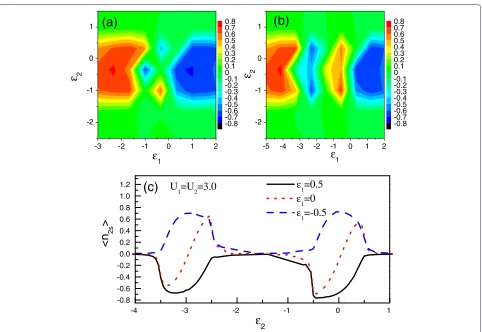
Figure 3The AB interferometer with two QDs.(a)Schematic of an AB interferometer with one QD in each of its arm.(b)The spin accumulation in QD-2 influenced by the properties of the other arm.(c)The influence of the QD levels on the spin accumulation in QD-2.(d)The spin
[image:5.595.62.539.354.694.2][Grσ]−1=
⎡ ⎢ ⎢ ⎢ ⎢ ⎣
gLr−1 0 −VL1 −VL2
0 gRr−1 −VR1 −VR2 −VL∗1 −VR∗1 g1r−σ1 0 −VL∗2 −VR∗2 0 g2r−σ1
⎤ ⎥ ⎥ ⎥ ⎥
⎦, (8)
wheregjrσ = 1−njσ¯
ω−εj+i0++
njσ¯
ω−εj−Uj+i0+ within the Hubbard approximation. Surely, Equation 5 is still suitable for eval-uating the electron properties of this system.
Without loss of generality, we take QD-2 as an exam-ple to investigate the spin accumulation behaviors of such a structure. In the presence of magnetic flux, the cou-pling coefficients take the following form:VL1 =V1eiφ/4, VR∗1 = V1eiφ/4,VR2 = V2eiφ/4, and VL∗2 = V2eiφ/4.Vj is the strength of the QD-lead coupling. The numerical results are shown in Figure 3b,c,d. In Figure 3b, by fixing φ= π2,ε2=0, andV2=0.1, we plot the spectrum of spin accumulation in QD-2 vsε1andV1. It is obvious that the increase ofV1can efficiently enhance the spin accumula-tion in QD-2. This means that in the case of finite spin bias and magnetic flux, a nonresonant channel is neces-sary to realize the spin accumulation of such a structure. So, it is the AB-Fano effect, but not the AB effect, that pro-motes the spin accumulation. Besides, it shows that the level of QD-1 plays a nontrivial role in affecting the spin accumulation. To be precise, when the level of QD-1 is shifted around the zero energy point, there will be no spin accumulation in QD-2. When the level of QD-1 departs from the zero energy, finite spin accumulation emerges with its maximum approximately at the position where V1 = 0.45√|ε1|. The other important result is that the sign ofn2swill change when the levelε1exceeds the zero energy point. Therefore, in comparison with the one-QD AB interferometer, we can find that the spin accumulation of this structure can be manipulated flexibly.
Next, we chooseV1=0.6 and investigate the spin accu-mulation in QD-2 influenced by the change of QD levels, as shown in Figure 3c. We find that similar to the for-mer structure, the spin accumulation occurs only when the corresponding QD level is located in the spin bias win-dow. However, the characteristic ofn2slies where its sign (+/−) is differentiated by the line ofε1 = ε2, where the spin accumulation disappears. This result indicates that if the spin bias is large enough, at the point ofε1 = 0, the sign ofn2scan be altered by the change of ε2. On the other hand, in Figure 3d, we investigaten2sas func-tions of φ andε2. The QD-lead couplings are taken to V1=5V2=0.5, and the level of QD-1 is fixed atε1=1. It is seen that the reversal of the magnetic flux direction can change the sign of spin accumulation, but in such a structure, the level of QD-2 tends to affect the maximum of spin accumulation, which appears around the points of ε2 = 0.25 andφ = ±0.3π. Thereby, we notice that the properties of the resonant channel, e.g., the level of QD-2,
are also important factors to change the magnitude of the spin accumulation.
For such a structure, it is difficult for us to write out the analytical expression ofn2s. So, we can only present a qualitative discussion to explain the above results by ana-lyzing the quantum interference that contributes to the spin accumulation. Obviously, the expression ofGr2α,σcan be written as the summation of two Feynman paths, i.e., G2rα,σ =τ2(α1),σ+τ2(α2),σ. Then, the quantum interference fea-ture determines the coupling strength between QD-2 and the leads. However, it is found that
τ2(1L),σ = ∞
j=1
i(−˜g2rσ21g˜r1σ)j j−1 12 V˜1L,
τ2(2L),σ = ∞
j=0 ˜
g2rσ(−˜g2rσg˜1rσ1221)jV˜2L, (9)
whereV˜jα = ˜Vα∗j = Vα∗j√πρandg˜rjσ =[ω−εj+ijj]−1 withjl = απVαjVα∗lρ. So, the coupling between QD-2 and lead-Lis determined by the quantum interference among infinite-order Feynman paths, different from that in the one-QD structure. This inevitably leads to the com-plicated features of the spin accumulation. Similarly, the three transmission paths between lead-Rand QD-2 can be given by
τ2(1R),σ = ∞
j=1
i(−˜g2rσ21g˜1rσ)j j−1 12 V˜1R,
τ1(2R),σ = ∞
j=0 ˜
g2rσ(−˜gr2σg˜1rσ1221)jV˜2R. (10)
Despite the complicated quantum interferences among infinite paths, we try to clarify the quantum interfer-ence feature by calculating the phase differinterfer-ences between the lowest-order paths. This is because the quantum interference among lowest-order paths contributes mainly to the coupling between QD-2 and the leads. For instance, the three lowest-order paths between QD-2 and lead-L are τ2(1,L,aσ) = −ig˜2rσV˜2LV˜L1g˜r1σV˜1L, τ
(1,b) 2L,σ = −ig˜2rσV˜2RV˜R1g˜r1σV˜1L, andτ
(2,0)
2L,σ = ˜g2rσV˜2L, and the phase differences areθ2(aL,,bσ) = φ,θ2(La,,0σ) = θ1+ φ2 − π2, and θ2(bL,0,σ)=θ1−π2, respectively, withθjbeing the argument
ofg˜jrσ. By a same token, we have the results thatτ2(R1,,aσ) = −ig˜2rσV˜2LV˜L1˜g1rσV˜1R, τ
(1,b)
2R,σ = −ig˜r2σV˜2RV˜R1˜g1rσV˜1R, and τ2(R2,0,σ)= ˜g2rσV˜2R; andθ2(Ra,,bσ)=φ,θ
(a,0) 2R,σ =θ1+
φ 2+
π 2, and θ2(bR,0,σ)=θ1+ π2. For a typical case ofω=0,ε1=1, and
φ = π2, we get the result thatθ2(aL,,bσ) = π2,θ2(aL,0,σ) = π,
from lead-L. In such a case, however, the quantum inter-ference amongτ2(1,R,aσ),τ2(2,R,bσ), andτ2(0R),σ is constructive since θ2(aR,,bσ)= π2,θ2(aR,0,σ)=0, andθ2(Rb,0,σ)= π4. Thus, the spin bias of lead-Rdetermines the spin accumulation in QD-2. Surely,θ1is dependent onω, but one should understand that the quantum interference ofω = 0 makes the main contribution to the spin accumulation. So, the accumu-lation of this structure. Meanwhile, note that only when the arm of QD-1 offers a nonresonant channel are the magnitudes of the paths close to one another, so that the quantum interference effect is clear.
Next, we demonstrate the effect of ε2 on the value of n2s. In Equations 9 to 10, one can find that in the higher-order paths, the two arms of the interferometer are visited repeatedly. Then, the properties of the two arms play an important role in affecting the quantum interfer-ence. In the study by Gong et al. [63], our calculations showed that when the levels of the two QDs are the same, the quantum interference between the two arms become weak, but only the nonresonant one determines the elec-tron properties of this structure. As a consequence, in
such a case, the interferometer can be considered as a single-channel structure, and then, the picture of quantum interference disappears. With this viewpoint, we under-stand the vanishment of the spin accumulation in the case ofε1=ε2.
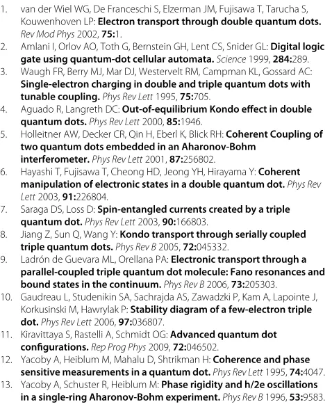
In Figure 4, by choosingV1=0.5,V2=0.1, andφ = π2, we investigate the influence of the intradot Coulomb interactions on the spin accumulation in QD-2. From Figure 4a,b,c, we clearly find that the many-body effect in QD-2 (i.e., the resonant-channel QD) on the spin accu-mulation is similar to that in the single-QD AB interfer-ometer. Namely, in the case ofU2 ≤ eVs, e.g.,U2 = 1.0, the energy region where the spin accumulation emerges is directly widened. As a result, the spin polarization is always robust in the whole region of−eVs
2 −U2< ε < eVs
2 . In the case of strong Coulomb interaction, e.g.,U2 = 3.0 in Figure 4c, the spectrum ofn2svsε2 is divided into two groups, which are analogous to each other. This result is easy to understand in terms of the analysis about the many-body effect in the above subsection. Alternatively, in Figure 4a,b,c we see that the Coulomb interaction with the
-3 -2 -1 0 1 2
-2 -1 0 1
<n
2s
>
ε
2(b)
(a)
ε
1ε
2-0.8 -0.7 -0.6 -0.5 -0.4 -0.3 -0.2 -0.1 0 0.1 0.2 0.3 0.4 0.5 0.6 0.7 0.8
ε
1ε
2-5 -4 -3 -2 -1 0 1 2
-2 -1 0 1
-0.8 -0.7 -0.6 -0.5 -0.4 -0.3 -0.2 -0.1 0 0.1 0.2 0.3 0.4 0.5 0.6 0.7 0.8
-4 -3 -2 -1 0 1
-0.8 -0.6 -0.4 -0.2 0.0 0.2 0.4 0.6 0.8 1.0
1.2
U
1
=U
2=3.0
ε1=0.5
ε1
=0
[image:7.595.59.541.361.693.2]ε1
=-0.5
(c)
Figure 4The influence of Coulomb interactions on the spectra ofn2s.The relevant parameters are taken to beV1=0.5,V2=0.1, and
φ= π2.(a)The spectrum ofn2svsε1andε2. The Coulomb interactions are taken to beU1=U2=1.0.(b)The spectrum ofn2swithU1=3.0
nonresonant channel plays a more significant role in mod-ifying the spin accumulation. First, a nonzeroU1causes the energy region where the positive spin accumulation appears to shift to the low-energy direction, and only when varyingε1toε1+U1 ≤0 can one see the positive spin accumulation. Secondly, with the further increase of U1, in the middle-energy region whereε1<0< ε1+U1, finite spin accumulation in QD-2 is also observed. For instance, for the case ofU1 = 3.0, positiven2scomes up around the point ofε1 = −0.5, whereas the negative n2soccurs in the vicinity ofε1 = −2.5. We explain this result as follows. A finiteU1will lead toε1splitting into ε1andε1+U1. Accordingly, two nonresonant channels contribute to the quantum interference. WhenU1 = 1.0, the two nonresonant channels have the opportunity to simultaneously act on the quantum interference. In the case of−1.0 < ε1 < 0.0, the sign ofε1+U1is greater than zero. Then, the electron waves in the two channels are phase-opposite, which significantly weakens the quan-tum interference and suppresses the spin accumulation in QD-2. However, for a strong Coulomb interaction in QD-1, whenε1is tuned below the zero energy point, the level ε1 + U1 is still much greater than zero. Then in such a case, the Coulomb-induced level contributes little to the quantum interference, and a single-electron inter-ference picture remains. Due to this reason, we find the positive spin accumulation in QD-2 whenε1 = −0.5 in Figure 4b,c. On the contrary, whenε1= −2.5,ε1+U1= 0.5. Then, the coupling betweenε1+ U1 and the leads provides a channel for the quantum interference, leading to the appearance of negative spin accumulation in QD-2. The further decrease ofε1will causeε1+U1to be less than zero. Compared with the result ofε1 = −2.5, the change of the sign ofε1+U1brings about the positiven2s. In addition, note that whenε1 = −U21, one can obtain the result ofε1 = −ε1+U1. Then, the opposite-phase elec-tron waves in the two nonresonant channels contribute zero to the quantum interference, so in such a case, no spin accumulation occurs in QD-2.
Summary
In summary, we have studied the spin accumulation char-acteristics of two AB interferometers with QDs embedded in their arms by considering spin bias in the leads. It has been found that regardless of the configurations of the interferometers, the spin accumulations are strongly dependent on the quantum interference features of the interferometers. Namely, the nonresonant transmission ability between the leads and the local magnetic flux can efficiently adjust the spin accumulation properties of the QD. By analyzing the quantum interferences among the Feynman paths, it was seen that the quantum interfer-ences can cause the QD in the resonant channel to be decoupled from one of the leads. Accordingly, the spin
bias in one lead will drive the spin accumulation in such a QD. So, it is certain that the AB-Fano effect assists to manipulate the spin accumulation. Further analysis showed that the double-QD interferometer has advan-tages in manipulating the spin states in the resonant channel. In view of the obtained results, we propose the AB interferometers with QDs to be alternative candidates for spin manipulation in QD devices.
Competing interests
The authors declare that they have no competing interests.
Authors’ contributions
WJG designed the theoretical model, deduced the relevant formula, and drafted the manuscript. YH carried out the numerical calculations. GZW participated in the analysis about the results. AD improved the manuscript. All authors read and approved the final manuscript.
Acknowledgements
This work was financially supported by the National Natural Science Foundation of China (grant no. 10904010), the Natural Science Foundation of Liaoning Province (grant no. 201202085), the Fundamental Research Funds for the Central Universities (grant no. N110405010), and China Postdoctoral Science Foundation (grant no. 20100481206).
Author details
1College of Sciences, Northeastern University, Shenyang, 110819, China. 2Department of Physics, Liaoning University, Shenyang, 110036, China. 3International Centre for Materials Physics, Chinese Academy of Sciences, Shenyang, 110016, China.
Received: 11 April 2012 Accepted: 20 July 2012 Published: 17 September 2012
References
1. van der Wiel WG, De Franceschi S, Elzerman JM, Fujisawa T, Tarucha S, Kouwenhoven LP:Electron transport through double quantum dots.
Rev Mod Phys2002,75:1.
2. Amlani I, Orlov AO, Toth G, Bernstein GH, Lent CS, Snider GL:Digital logic
gate using quantum-dot cellular automata.Science1999,284:289.
3. Waugh FR, Berry MJ, Mar DJ, Westervelt RM, Campman KL, Gossard AC:
Single-electron charging in double and triple quantum dots with
tunable coupling.Phys Rev Lett1995,75:705.
4. Aguado R, Langreth DC:Out-of-equilibrium Kondo effect in double
quantum dots.Phys Rev Lett2000,85:1946.
5. Holleitner AW, Decker CR, Qin H, Eberl K, Blick RH:Coherent Coupling of two quantum dots embedded in an Aharonov-Bohm
interferometer.Phys Rev Lett2001,87:256802.
6. Hayashi T, Fujisawa T, Cheong HD, Jeong YH, Hirayama Y:Coherent
manipulation of electronic states in a double quantum dot.Phys Rev
Lett2003,91:226804.
7. Saraga DS, Loss D:Spin-entangled currents created by a triple
quantum dot.Phys Rev Lett2003,90:166803.
8. Jiang Z, Sun Q, Wang Y:Kondo transport through serially coupled
triple quantum dots.Phys Rev B2005,72:045332.
9. Ladr ´on de Guevara ML, Orellana PA:Electronic transport through a parallel-coupled triple quantum dot molecule: Fano resonances and
bound states in the continuum.Phys Rev B2006,73:205303.
10. Gaudreau L, Studenikin SA, Sachrajda AS, Zawadzki P, Kam A, Lapointe J, Korkusinski M, Hawrylak P:Stability diagram of a few-electron triple dot.Phys Rev Lett2006,97:036807.
11. Kiravittaya S, Rastelli A, Schmidt OG:Advanced quantum dot
configurations.Rep Prog Phys2009,72:046502.
12. Yacoby A, Heiblum M, Mahalu D, Shtrikman H:Coherence and phase
sensitive measurements in a quantum dot.Phys Rev Lett1995,74:4047.
13. Yacoby A, Schuster R, Heiblum M:Phase rigidity and h/2e oscillations
14. Buks E, Schuster R, Heiblum M, Mahalu D, Umansky V:Dephasing in
electron interference by a ‘which-path’ detector.Nature (London)
1998,391:871.
15. Schuster R, Buks E, Heiblum M, Mahalu D, Umansky V, Shtrikman H:Phase measurement in a quantum dot via a double-slit interference
experiment. Nature.(London)1997,385:417.
16. Avinun-Kalish M, Heiblum M, Zarchin O, Mahalu D, Umansky V:Crossover from ‘mesoscopic’ to ‘universal’ phase for electron transmission in
quantum dots.Nature (London)2005,436:529.
17. Holleitner AW, Decker CR, Qin H, Eberl K, Blick RH:Coherent coupling of two quantum dots embedded in an Aharonov-Bohm
interferometer.Phys Rev Lett2001,87:256802.
18. Kobayashi K, Aikawa H, Katsumoto S, Iye Y:Tuning of the Fano effect
through a quantum dot in an Aharonov-Bohm interferometer.Phys
Rev Lett2002,88:256806.
19. Kobayashi K, Aikawa H, Sano A, Katsumoto S, Iye Y:Fano resonance in a
quantum wire with a side-coupled quantum dot.Phys Rev B2004,
70:035319.
20. Sigrist M, Ihn T, Ensslin K, Reinwald M, Wegscheider W:Coherent
probing of excited quantum dot states in an interferometer.Phys Rev
Lett2007,98:036805.
21. Aharony A, Entin-Wohlman O, Otsuka T, Katsumoto S, Aikawa H, Kobayashi
K:Breakdown of phase rigidity and variations of the Fano effect in
closed Aharonov-Bohm interferometers.Phys Rev B2006,73:195329.
22. Kubo T, Tokura Y, Hatano T, Tarucha S:Electron transport through Aharonov-Bohm interferometer with laterally coupled double
quantum dots.Phys Rev B2006,74:205310.
23. Hatano T, Kubo T, Tokura Y, Amaha S, Teraoka S, Tarucha S:
Aharonov-Bohm oscillations changed by indirect interdot tunneling via electrodes in parallel-coupled vertical double quantum dots.
Phys Rev Lett2011,106:076801.
24. Yeyati AL, B ¨utiker M:Aharonov-Bohm oscillations in a mesoscopic
ring with a quantum dot.Phys Rev B1995,52:R14360.
25. Hackenbroich G, Weidenm ¨uler HA:Transmission through a quantum
dot in an Aharonov-Bohm ring.Phys Rev Lett1996,76:110.
26. Weidenm ¨uler HA:Transmission phase of an isolated Coulomb
blockade resonance.Phys Rev B2002,65:245322.
27. Hofstetter W, K ¨onig J, Schoeller H:Kondo correlations and the Fano
effect in closed Aharonov-Bohm interferometers.Phys Rev Lett2001,
87:156803.
28. Pala MG, Iannaccone G:Effect of dephasing on the current statistics of
mesoscopic devices.Phys Rev Lett2004,93:256803.
29. Bułka BR, Stefa ´nski P:Fano and Kondo resonance in electronic current
through nanodevices.Phys Rev Lett2001,86:5128.
30. Urban D, K ¨onig J:Coulomb-interaction effects in full counting
statistics of a quantum-dot Aharonov-Bohm interferometer.Phys Rev
B2008,78:075318.
31. Osawa K, Kurihara S, Yokoshi N:Fano effect in a Josephson junction
with a quantum dot.Phys Rev B2008,78:224508.
32. Aharony A, Entin-Wohlman O, Imry Y:Measuring the transmission
phase of a quantum dot in a closed interferometer.Phys Rev Lett2003,
90:156802.
33. Lim JS, L ´opez R, Platero G, Simon P:Transport properties of a molecule
embedded in an Aharonov-Bohm interferometer.Phys Rev B2010,
81:165107.
34. Fang T-F, Wang S-J, Zuo W:Flux-dependent shot noise through an Aharonov-Bohm interferometer with an embedded quantum dot.
Phys Rev B2007,76:205312.
35. Moldoveanu V, Tolea M, Gudmundsson V, Manolescu A:Fano regime of
one-dot Aharonov-Bohm interferometers.Phys Rev B2005,72:085338.
36. Hiltscher B, Governale M, K ¨onig J:Spin-dependent transport through
quantum-dot Aharonov-Bohm interferometers.Phys Rev B2010,
82:165452.
37. Vernek E, Sandler N, Ulloa SE:Kondo screening suppression by
spin-orbit interaction in quantum dots.Phys Rev B2009,80:041302(R).
38. Heary RJ, Han JE, Zhu L:Spin-charge filtering through a spin-orbit coupled quantum dot controlled via an Aharonov-Bohm
interferometer.Phys Rev B2008,77:115132.
39. Wolf SA, Awschalom DD, Buhrman RA, Daughton JM, von Molnr S, Roukes ML, Chtchelkanova AY, Treger DM:A spin-based electronics vision for
the future.Science2001,294:1488.
40. Prinz GA:Magnetoelectronics.Science1998,282:1660. 41. Zutic I, Fabian J, Das SarmaS:Spintronics: Fundamentals and
applications.Rev Mod Phys2004,76:323.
42. Hanson R, Kouwenhoven LP, Petta JR, Tarucha S, Vandersypen LMK:Spins
in few-electron quantum dots.Rev Mod Phys2004,79:1217.
43. Recher P, Sukhorukov EV, Loss D:Quantum dot as spin filter and spin
memory.Phys Rev Lett2000,85:1962.
44. Paillard M, Marie X, Renucci P, Amand T, Jbeli A, G´erard JM:Spin
relaxation quenching in semiconductor quantum dots.Phys Rev Lett
2001,86:1634.
45. Cortez S, Krebs O, Laurent S, Senes M, Marie X, Voisin P, Ferreira R, Bastard G, G´erard J-M, Amand T:Optically driven spin memory in n-doped
InAs-GaAs quantum dots.Phys Rev Lett2002,89:207401.
46. Besombes L, L´Ieger Y, Maingault L, Ferrand D, Mariette H, Cibert J:
Probing the spin state of a single magnetic ion in an individual
quantum dot.Phys Rev Lett2004,93:207403.
47. Sun QF, Wang J, Guo H:Quantum transport theory for nanostructures
with Rashba spin-orbital interaction.Phys Rev B2005,71:165310.
48. Wang B, Wang J, Wang J, Xing DY:Spin current carried by magnons.
Phys Rev B2004,69:174403.
49. Cummings AW, Akis R, Ferry DK:Electron spin filter based on Rashba
spin-orbit coupling.Appl Phys Lett2006,89:172115.
50. Li J, Shen SQ:Spin-current-induced charge accumulation and electric current in semiconductor nanostructures with Rashba spin-orbit
coupling.Phys Rev B2007,76:153302.
51. Zhang P, Xue QK, Xie XC:Spin current through a quantum dot in the
presence of an oscillating magnetic field.Phys Rev Lett2003,
91:196602.
52. Lu H-Z, Shen S-Q:Using spin bias to manipulate and measure spin in
quantum dots.Phys Rev B2008,77:235309.
53. Lu H-Z, Shen S-Q:Detecting and switching magnetization of Stoner
nanograin in nonlocal spin valve.Phys Rev B2009,80:094401.
54. Lu H-Z, Zhou B, Shen S-Q:Spin-bias driven magnetization reversal
and nondestructive detection in a single molecular magnet.Phys Rev
B2009,79:174419.
55. Xing YX, Sun QF, Wang J:Spin bias measurement based on a quantum
point contact.Appl Phys Lett2008,93:142107.
56. Jedema FJ, Heersche HB, Filip AT, Baselmans JJA, van Wees BJ:Electrical detection of spin precession in a metallic mesoscopic spin valve.
Nature2002,416:713.
57. Kobayashi T, Tsuruta S, Sasaki S, Fujisawa T, Tokura Y, Akazaki T:Kondo Effect in a semiconductor quantum dot with a spin-accumulated
lead.Phys Rev Lett2010,104:036804.
58. Frolov SM, L ¨uscher S, Yu W, Ren Y, Folk JA, Wegscheider W:Ballistic spin
resonance.Nature2009,458:868.
59. Katsura H:Nonequilibrium Kondo problem with spin-dependent
chemical potentials: exact results.J Phys Soc Jpn2007,76:054710.
60. Bao Y-J, Tong N-H, Sun Q-F, Shen S-Q:Conductance plateau in quantum spin transport through an interacting quantum dot.
Europhys Lett2008,83:37007.
61. Meir Y, Wingreen NS:Landauer formula for the current through an
interacting electron region.Phys Rev Lett2512,68:1992.
62. Souza FM, Jauho AP, Egues JC:Spin-polarized current and shot noise in the presence of spin flip in a quantum dot via nonequilibrium
Green’s functions.Phys Rev B2008,78:155303.
63. Gong W, Xie X, Wei G:Coulomb-modified equilibrium and nonequilibrium properties in a double quantum dot
Aharonov-Bohm-Fano interference device.J Appl Phys2010,
107:073702.
doi:10.1186/1556-276X-7-510