CONTROL
DATA®
ftl"" • • U ft ... ftlll
UI~rLA' ~IAllun
CC505-A,B
• General Description
• Operation and Programming
• Installation and Checkout
• Theory of Operation
• Diagrams
• Maintenance
• Maintenance Aids
CONTROL DATA
DISPLAY STATION
CC505-A,B
HARDWARE REFERENCE/CUSTOMER ENGINEERING MANUAL
SECTIONS IN THIS MANUAL:
Section I
Section II
Section III
Section IV
Section V
Section VI
Section VII
General Description
Operation and Programming
Insta Ilation and Checkout
Theory of Operation
Diagrams
Maintenance
Maintenance Aids
Any comments concerning this publ ication should be addressed to:
Control Data Corporation Techn ical Publ ications Department
2401 North Fairview Avenue St. Paul, Minnesota 55113
or use comment sheet at the back of th is book
Publication No. 82128500 December 1968
REVI S ION
A-O-O
n
"
"
u-v-v
C-O
Released
Display Station
CC505-A, B
REVISION RECORD
DESCRIPTION
(03-14-68) Reflects configuration as I isted on page liB ".
Rcpliiltccl vvith Rc'vi5iv(,
n
1-26-68}Reprinted with Revision (07-06-72)
FOREWORD
CONTROL DATA Equipments CC505-A and CC505-B are modularized Entry and Display Stations (referred to hereafter as Display Stations) which provide basic data inquiry and retrieval functions.
Visual aids included in this manual are signal waveforms and a Display Station schematic diagram containing important signal waveforms and voltage levels. These provide the trained customer engineer with a useful tool.
The only difference between the two Display Stations is the input power requirement; Type A requires 105- to 125-volt ac, 47- to 400-hertz, 1.25-ampere power and type B requires 210- to 250-volt ac, 47- to 400-hertz, 0.63 ampere power.
This manual contains information necessary for operating and maintaining the Display Station. There are seven sections as follows.
Section I, General Description - gives the functional and operational
descrip-tion, physical descripdescrip-tion, and electrical data .
.
Section II, Operation and Programming -
I
ists all operating controls, operatingprocedures, and programming information.
Section III, Installation and Checkout - describes crating and uncrating, physical
limitations, power requirements, cabling and connectors, cooling requirements, environmental considerations, mounting procedures, test procedures, and specific checkout instructions.
Section IV, Theory of Operation - presents general and detai led functional
descriptions of the equipment.
Section V, Diagrams - contains all applicable schematic and interconnection
diagrams.
Section VI, Maintenance - provides maintenance, troubleshooting, parts removal
FOREWORD (CONT)
Section VII, Maintenance Aids - contains card placement charts, circuit card
diagrams, fuse data, timing charts, and a list of common malfunctions with possible
causes and corrections 0
For parts information on the Display Station, refer to the following publ ication:
CC505-A,B Display Station Parts Data Book
TABLE OF CONTENTS
Section Page
I
--
GENERAL DESCRIPTIONFunctional Description
1- 1
Environmental Data
1-2
Physical Data
1-3
E lectrica
I
Data1-3
II OPERATION AND PROGRAMMING
Controls
2-1
Keyboard Lockout
2-4
Operating Procedures
2-5
Turn On/T urn Off
2-5
Message Compos i ng
2-5
Message Editing 2~6
Spec ial Keyboard Functions
2-7
Keyboard Codes
2-9
III INSTALLATION AND CHECKOUT
Crating Instructions
3-1
Uncrating Instructions
3-1
Power Requirements
3-4
Cabling
3-4
Cool ing Requ irements
3-5
E nv i ronme nta
I
Cons ide rat ions3-5
Checkout
3-5
IV THEORY OF OPERATION
Monitor Assembly
4-1
Cathode Ray Tube
4-2
Low Voltage
4-2
High Voltage
4-2
Deflection
4-5
Keyboard Assembly
4-22
Switch and Relay
4-22
Diode Encoder
4-22
TABLE OF CONTENTS (CaNT)
Section Page
V DIAGRAMS 5-1/2
VI MAINTENANCE
Test Equipment Required 6-1
Preventive Maintenance Index (PMI) 6-2
Preventive Maintenance Procedures (PMP) 6-2
Weekly Procedures 6-2
Monthly Procedures 6-2
Quarterly Procedures 6-5
Corrective Maintenance 6-6
Adj ustments 6-6
Diagnostic Procedures 6-16
Remove and Replace Procedures 6- 18
VII MAINTENANCE AIDS
Fuse 7-1
Card Placement Chart 7-1
Card Diagrams 7-1
Switch Symbols 7-2
LIST OF ILLUSTRATIONS
Section Figure
GENERAL DESCRIPTION
1- 1 Display Station
II OPERATION AND PROGRAMMING
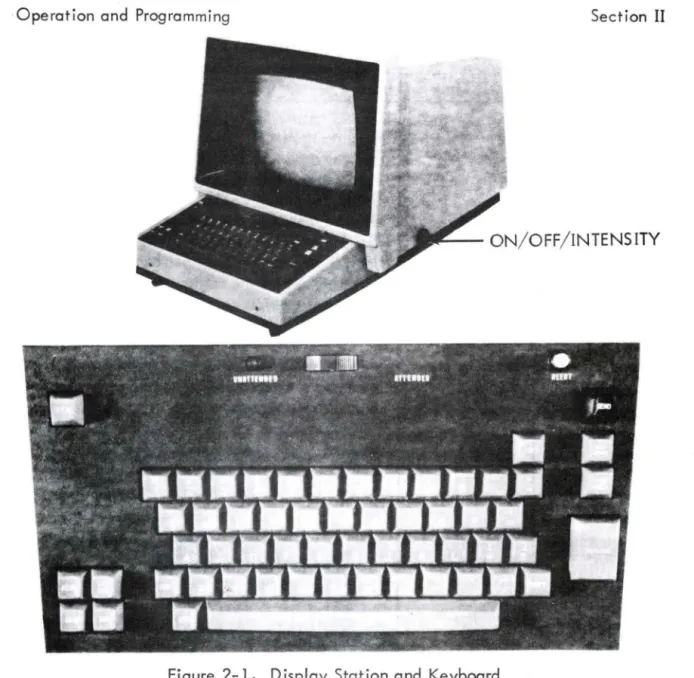
2-1 Display Station and Keyboard
III INSTALLATION AND CHECKOUT
3-1 3-2
Display Station Interior View Display Station Card Location
IV - - THEORY OF OPERATION
4-1 4-2 4-3 4-4A 4-4 4-5A 4-5 4-6A
4-6
4-7 4-8Display Station Block Diagram
High-Voltage Assembly Simpl ified Block Diagram Vol tage Doubl ing Steps
Card Type 044(Series A) Card Type 044
Card Type 044A(Series A) Card Type 044A
Card Type 046
Card Type 046(Series A) Card Type 211
Card Type 491
V DIAGRAMS
5-1 5-2 5-3 5-4 5-5 5-5A
Schematic Diagram, Display Station
Interconnection Diagram, Monitor Assembly (115 Vol ts - 60 Hertz)
Interconnection Diagram, Monitor Assembly (230 Vol ts - 50 Hertz)
Schematic Diagram, Defl ection Assembly Schematic Diagram, Low-Voltage Assembly
( 115 Volts - 60 Hertz)
Schematic Diagram , Low-Vol tage Assembly (115 Vol ts - 60 Hertz)
LIS T 0 F ILL US T RA T ION S ( CON T)
Section Figure
V - 5-6 Schematic Diagram, Low-Voltage Assembly
(230 Volts - 50 Hertz) 5-6A
5-7 5-7A 5-8 5-9 5-9A 5-10
Schematic Diagram, Low-Voltage Assembly (230 Volts - 50 Hertz)
Schematic Diagram, High-Voltage Assembly Schematic Diagram, High-Voltage Assembly Schematic Diagram, Yoke Assembly
Schematic Diagram, 7BQD Card (2 Sheets) Card Assembly, 7BQD
Interconnection Diagram, Alarm and Lights
VI - MAINTENANCE
6-1 Display Station Adjustment Points
6-2 Deflection Input Waveforms
6-3 High-Vol tage Adjustments
6-4 High-Voltage Power Supply Waveforms
VII - - MAINTENANCE AIDS
7-1 Card Component Identification
5-15/16
5-17/18 5-19/20 5-21/22 5-23/24 5-25/26 5-29/30 5-31/32
6-8
6-9 6-12 6-14
LIST OF TABLES
Section Table Page
I GE NERAL DESCRIPTION
1- 1 Environmental Conditions 1-2
II OPERATION AND PROGRAMMING
2-1 Display Station Controls 2-1
2-2 Turn-On/furn-Off Procedures 2-5
2-3 Message Composing Procedure 2-5
2-4 Editing Procedures 2-6
2-5 Spec ial Keyboard Functions 2-7
2-6 Keyboard Codes 2-9
III INSTALLATION AND CHECKOUT
3-1 Display Station Connector 3-4
VI MAINTENANCE
6-1 Recommended Test Equipment 6-1
6-1a Preventive Maintenance Index 6-2
6-2 Display Station Adjustments 6-3
6-3 Typ ical Deflection Waveforms 6-13
VII
-
MAINTENANCE AIDS7-1 Card Placement Chart 7-1
figure
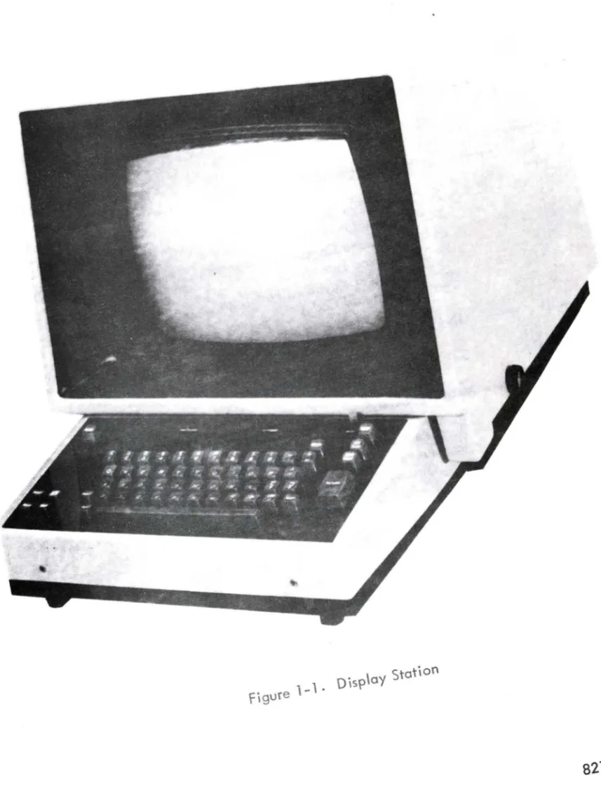
1-1.
Oisp\ay Station82128500
SECTION I
GENERAL DESCRIPTION
The Display Station described herein provides basic data inquiry and retrieval functions in a remote terminal configuration. Figure 1-1 shows the Display Station.
The Display Station is composed of two main assembl ies. An alphanumeric keyboard assembly enters data into the system and controls its destination. The monitor assembly conta ins deflection c ircu itry, vol tage-generating c ircu itry, and a crt for visual display of the keyboard-generated data. Any response from the central processing site (data source) is also displayed. Remote-site processing logic, symbol-generating logic, and a display memory are contained in the Equipment
Controller ·
Display screen data is refreshed at a rate greater than 50 cycles per second. Symbol intensity, adjustable by the operator, is suffic ient for viewing under normal
I
ighting conditions. The crt has a diagonal measurement of 14 inches with a nominal6-inch-high by 8-inch-wide viewing area. Viewing area and symbol size adjust-ments may be made within the Display Station. Symbol size is normally 0.25 inches high by 0.12 inches wide.
Display format (an Equipment Controller function mentioned here only for reference) is either 20 lines of 50 symbols per line or 13 lines of 80 symbols per line.
FUNCTIONAL DESCRIPTION.
The following description refers to Display Station appl ication in a remote terminal configuration. Equipment Controller functions are explained, where nec-essary, to clarify Display Station operation.
Depressing a keyboard key transmits a 7-bit symbol code to the Equipment Controller. The code for each symbol selected on the keyboard is stored in the Display Station buffer memory and the symbol is displayed on the crt.
,~ .. , - '
. General Description Section I
as a broken
I
ine across the crt.As
the entry marker advances across the crt, theunderline chain decreases in length. The underl ine chain indicates how much typing remains on that line. Both the entry marker and the underl ine chain, therefore, are useful for message composition, editing, error correction, etc.
Once a message is complete, the operator may transmit either the entire message or a selected portion thereof by using one of two methods. In block mode of operation, the entire message content transmits to the data source (under control
of the data source) when the SEND key is depressed. This causes the symbol (a) to
appear at the current entry marker position and the entry marker to reset to the upper
left corner of the crt.
As
each word is read by the data source, the entry markeradvances until it reaches the symbol (.~). The entry marker stops one symbol
posi-tion to the right of this point. In line mode, the line indicator denotes which line of information beg ins transmission. In this mode of operation, the entry marker,
instead of being reset to the upper left corner of the crt, is reset to the beginning
of the
I
ine indicated by theI
ine indicator. Transmission then takes place as inblock mode except that transmission begins from the
I
ine indicated by the lineindicator.
Depress the AUX SE ND key to obtain a printed copy of the displayed message. This results in the display of the symbol (') at the current entry marker position. The entry marker then resets to the upper left corner of the crt. Data transmission begins at the upper left corner of the crt and ceases when the entry marker reaches the end
of print symbol (I). The keyboard locks out during this operation.
ENVIRONMENTAL DATA.
The Display Station is situated on top of the Equipment Controller next to
the control panel. For spec ified performance, observe environmental
I
imitationsI
isted in table 1-1.TABLE 1-1. ENVIRONMENTAL CONDITIONS
OPERATIONAL NONOPERATIONAL
CONDITION (Norma
I,
Standby, (Transit and Storage)and tv\aintenance) (Note 1)
Temperature
+
65 F to+
100 F - 65 F to+
160 FRelative Humidity 40 to 600f<, 10 to 900f<,. (Note 2)
Altitude 8,000 feet 12,000 feet
Note 1
-
packed for shipment., Section I General Description
PHYSICAL DESCRIPTION.
Physical construction of the Display Station incorporates latest recognized features in engineering, convenience, and safety, to operating personnel. The unit is 17-3/4 inches wide, 28-1/2 inches deep, and 16-5/8 inches high and it weighs 80 pounds.
The exterior consists of a crt screen for data viewing and a keyboard consist-ing of control keys for command signals and data entry.
Each of the assembl ies in the Display Station is interchangeable without major readjustment. Analog circuits may need to be readjusted after replacement of circuit cards or components. All parts bearing the same manufacturer's part number are electrically, mechanically, and functionally interchangeable. The unit is designed and constructed to permit ready access to all modules and to have a
nor-mal service
I
ife of at least 10 years, operating 24 hours a day, 7 days per week,with reasonable maintenance and replacement of parts.
ELECTRICAL DATA.
SECTION II
OPERATION AND PROGRAMMING
This section explains all Display Station operator controls. Display Station keyboard functions and data inquiry procedures explained in this section refer to the
Controller functions are explained, where necessary, to clarify Display Station operation. Section VI,Maintenance, explains maintenance adjustments.
CONTROLS.
NOTE
The ON/OFF/INTENSITY control disables the SHIFT key but does not disable any lower case symbols or functions. The characters are stored in memory but are not displayed on the Display Station crt.
The ON/OFF/INTENSITY control {on the lower right side of the Display Station} appl ies power to the Display Station. Further rotation adjusts symbol inten-sity. Actuation of Display Station keyboard keys enters data into the Equipment
Controller and classifies whether a displayed message is intended for printout ·or data source· Table 2-1 explains Display Station controls. Figure 2-1 shows the keyboard configuration.
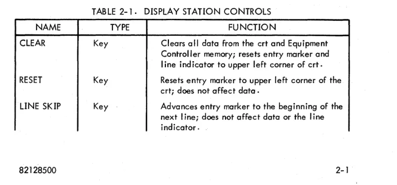
TABLE 2-1. DISPLAY STATION CONTROLS
NAME TYPE FUNCTION
CLEAR Key Clears a" data from the crt and Equipment
Controller memory; resets entry marker and line ind icator to upper left corner of crt.
RESET Key Resets entry marker to upper left corner of the
crt; does not affect data.
LINE SKIP Key Advances entry marker to the beginning of the
next I ine; does not affect data or the line
· Operation and Programming Section II
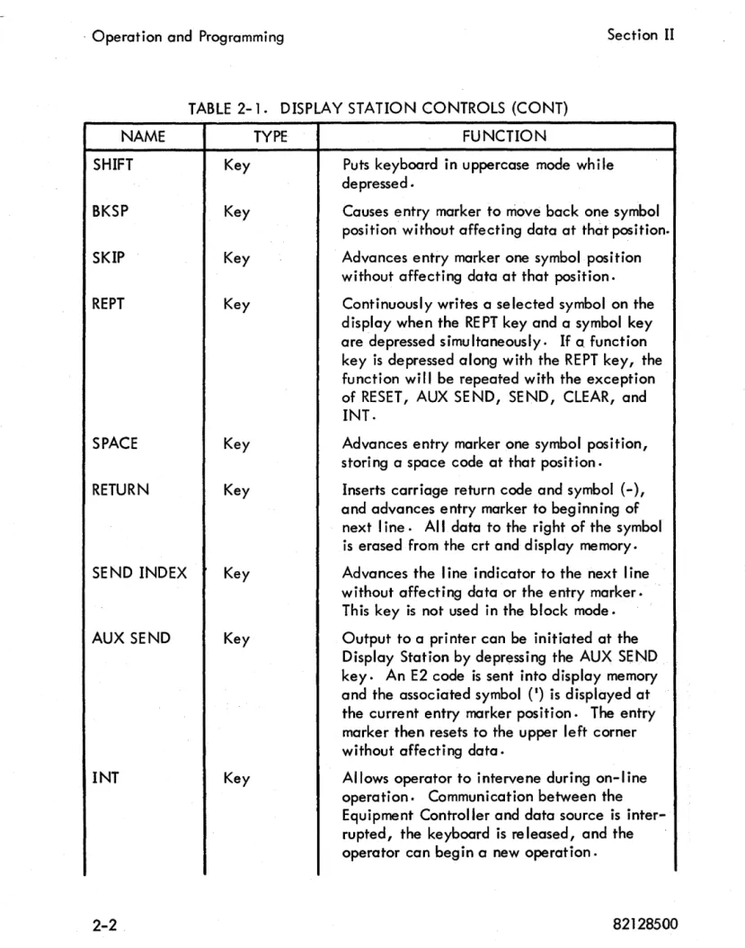
TABLE
2-1.
DISPLAY STATION CONTROLS (CONT)NAME
SHIFT Key
BKSP Key
SKIP Key
REPT Key
SPACE Key
RETURN Key
SEND INDEX Key
AUX SEND Key
INT Key
TYPE FUNCTION
Puts keyboard in uppercase mode while depressed ·
Causes entry marker to move back one symbol position without affecting data at that position.
Advances entry marker one symbol position without affecting data at that position.
Continuously writes a selected symbol on the display when the RE PT key and a symbol key
are depressed simultaneously. If a. function
key is depressed along with the REPT key, the function will be repeated with the exception of RESET, AUX SE NO, SE NO, CLEAR, and INT.
Advances entry marker one symbol position, storing a space code at that position.
Inserts carriage return code and symbol (-), and advances entry marker to beginning of next line. All data to the right of the symbol is erased from the crt and display memory.
Advances the
I
ine indicator to the next linewithout affecting data or the entry marker. This key is not used in the block mode.
Output to a printer can be initiated at the Display Station by depressing the AUX SEND key. An E2 code is sent into display memory
and the associated symbol (I) is displayed at
the current entry marker position. The entry marker then resets to the upper left corner without affecting data.
· Section II Operation and Programming
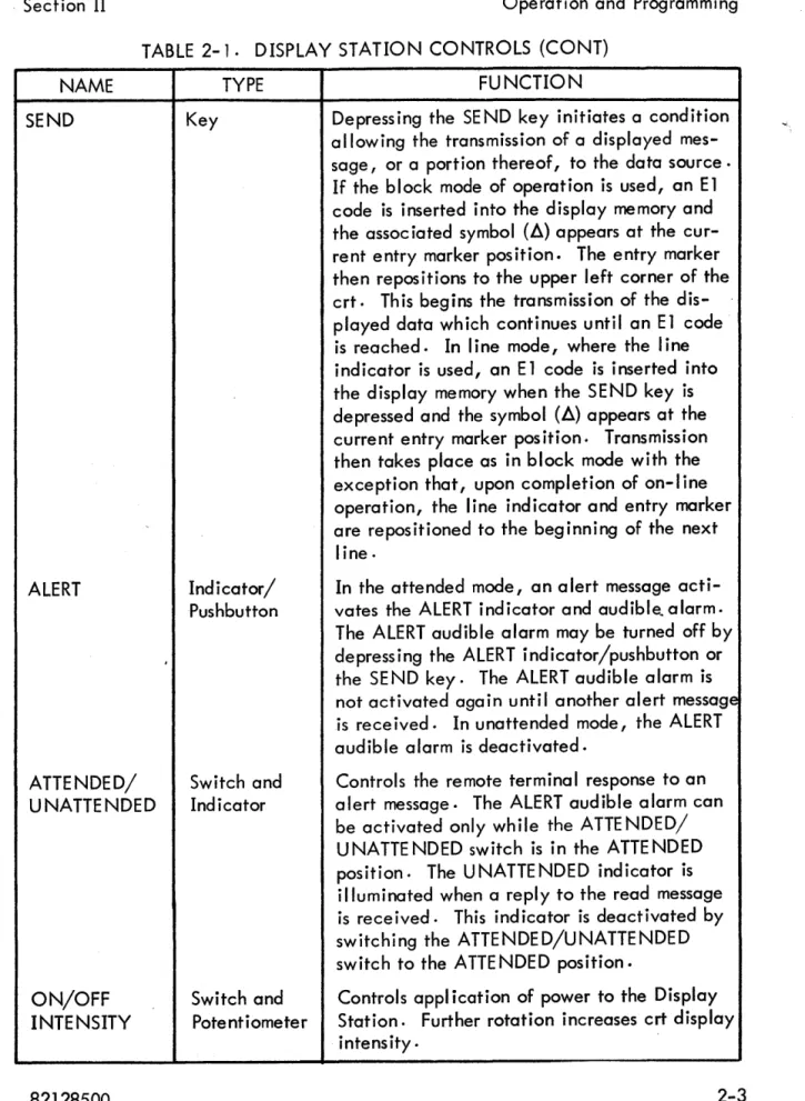
TABLE 2-1. DISPLAY STATION CONTROLS (CONT)
NAME
SEND
ALERT
ATTENDED/ UNATTENDED
ON/OFF INTENSITY
TYPE
Key
Indicator/ Pushbutton
Switch and Indicator
FUNCTION
Depress ing the SE ND key initiates a condition allowing the transmission of a displayed mes-sage, or a portion thereof, to the data source·
If the block mode of operation is used, an E1
code is inserted into the display memory and
the assoc iated symbol (~) appears at the
cur-rent entry marker position. The entry marker then repositions to the upper left corner of the crt. This begins the transmission of the dis-played data which continues until an E1 code is reached. In line mode, where the line indicator is used, an E 1 code is inserted into the display memory when the SEND key is
depressed and the symbol (~) appears at the
current entry marker pos ition. Transmission then takes place as in block mode with the exception that, upon completion of on-I ine operation, the line indicator and entry marker are repositioned to the beginning of the next
line.
In the attended mode, an alert message
acti-vates the ALERT indicator and audible~alarm.
The ALERT audible alarm may be turned off by depressing the ALERT indicator/pushbutton or the SE ND key. The ALERT audible alarm is not activated again until another alert message is rece ived. In unattended mode, the ALERT audible alarm is deactivated.
Controls the remote terminal response to an alert message. The ALERT audible alarm can be activated only while the ATTE NDED/ UNATTENDED switch is in the ATTENDED position. The UNATTENDED indicator is illuminated when a reply to the read message is rece ived. This ind icator is deact ivated by switching the ATTENDED/UNATTENDED switch to the ATTE NDED position.
Switch and Controls appl ication of power to the Display
Potentiometer Station. Further rotation increases crt display
Operation and Programming Section II
I ' L - - ON/OFF/INTENSITY
Figure 2-1. Display Station and Keyboard
KEYBOARD LOCK OUT.
The keyboard is inoperable (locked out) during the following operations.
(1) SEND key has been depressed and the desired type of write message has not been received for display on the crt.
(2) Receipt of a write message ending with an E2 or E3 code and a write message designated for display on the crt has not been received. (3) SEND key is depressed when the ATTENDED/UNATTENDED switch is
in the UNA HE NDED position.
. Section II Operation and Programming
The keyboard may be unlocked by (1) depress ing the I NT key wh ich unlocks
the keyboard immediately after the next write/acknowledge message sequence (unless the message ends with an E2 code), (2) depression of the MAN REL switch in the Equipment Controller, and (3) operation of the ATTENDED/UNATTENDED switch to ATTENDED position after a formal unattended mode.
OPERATING PROCEDURES.
Following paragraphs explain Display Station turn-on/turn-off, message composing, and editing procedures, and special keyboard functions.
TURN ON/TURN OFF.
Turn-on/turn-off procedures are
I
isted in table 2-2.TABLE 2-2. TURN-ON/TURN-OFF PROCEDURES
PROCEDURE OPERATION
Turn On Rotate the ON/OFF/INTENSITY control to the ON position.
After a 3D-second warmup period, rotate the 0 N/OFF / INTENSITY control until the marker chain, located on the . upper data line, is visible.
Turn Off Rotate the ON/OFF/INTENSITY control to the OFF position.
MESSAGE COMPOSING.
Table 2-3
I
ists the recommended procedure for composing a message.TABLE 2-3. MESSAGE COMPOSING PROCEDURE
STEP OPERATION DE SCRIPTIO N
Compose Compose a message by Each key depress ion causes its assoc iated
depressing various symbol code to be sent to the display memory
keys on the keyboc:i-rd. which causes the symbol to be displayed
, Operation and Programming Section II
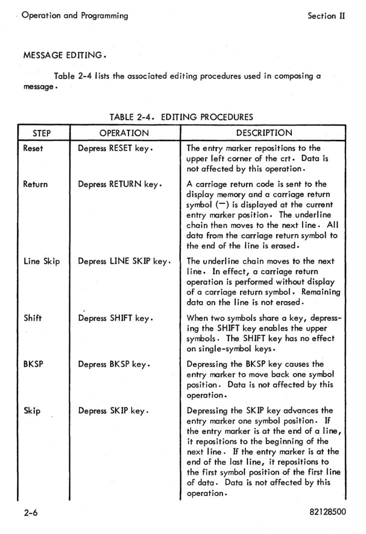
MESSAGE EDITING.
Table 2-4
I
ists the associated editing procedures used in composing amessage •
STEP
Reset
Return
Line Skip
Shift
BKSP
Skip
TABLE 2-4. EDITING PROCEDURES
OPERATION
Depress RESET key.
Depress RETURN key.
Depress LINE SKIP key.
Depress SHIFT key.
Depress BKSP key.
Depress SKIP key.
DESCRIPTION
The entry marker repositions to the upper left corner of the crt. Data is not affected by th is operation.
A carriage return code is sent to the
display memory and a carriage return symbol (-) is displayed at the current entry marker position. The underline chain then moves to the next line. All data from the carriage return symbol to the end of the line is erased.
The underl ine chain moves to the next line. In effect, a carriage return operation is performed without display of a carriage return symbol. Remaining data on the line is not erased.
When two symbols share a key, depress-ing the SHIFT key enables the upper symbols. The SHIFT key has no effect on single-symbol keys.
Depressing the BKSP key causes the entry marker to move back one symbol position. Data is not affected by this operation.
Depressing the SKIP key advances the entry marker one symbol position. If the entry marker is at the end of a line, it repositions to the beginning of the
next line. If the entry marker is at the
Section II
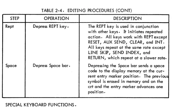
STEP
Rept
Space
Operation and Programming
TABLE
2-4.
EDITING PROCEDURES (CONT)OPERATION
Depress REPT key.
Depress Space bar.
DESCRIPTION
The REPT key is used in conjunction with other keys. It initiates repeated action. All keys work with REPT except RESET, AUX SEND, CLEAR, and INT. All keys repeat at the same rate except LINE SKIP, SEND INDEX, and
RETURN, which repeat at a slower rate.
Depressing the Space bar sends a space code to the display memory at the cur-rent entry marker position. The previous symbol is erased in memory and on the crt and the entry marker advances one position.
SPECIAL KEYBOARD FUNCTIONS.
Table
2-5 I
ists special keyboard functions used in conjunction with otherkeyboard controls.
TABLE
2-5.
SPECIAL KEYBOARD FUNCTIONSSTEP OPERATION DESCRIPTION
Send Index Depress SE ND INDEX Operator controls the position of the
key.
I
ine indicator with the SE ND INDEXkey. Each depression causes the line indicator to advance one line and, upon reaching the last line, to reposi-tion it back to the first line. The entry marker is not affected.
Aux Send Depress AUX SE ND key. Operator initiates message printout by
depressing the AUX SEND key. An E2 code is sent to the display memory and the associated symbol (') is displayed at the current entry marker position. The underl ine chain then resets to the
upper data
I
ine without affecting data..Operation and Programming Section II
TABLE 2 ..
5.
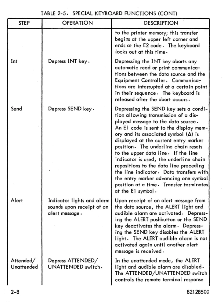
SPECIAL KEYBOARD FU NCTIONS (CONT)STEP
Int
Send
Alert
Attended/ Unattended
OPERATION
Depress INT key.
Depress SEND key.
Indicator
I
ights and alarmsounds upon receipt of an a Ie rt message.
Depress ATTENDED/ UNATTENDED switch.
DESCRIPTION
to the printer memory; this transfer begins at the upper left corner and ends at the E2 code. The keyboard
locks out at this ti me.
Depressing the INT key aborts any automatic read or print communica-tions between the data source and the Equipment Controller. Communica:-tions are interrupted at a certain point in their sequence. The keyboard is released after the abort occurs.
Depressing the SEND key sets a condi-tion allowing transmission of a dis-played message to the data source·
An E 1 code is sent to the display
mem-ory and its associated symbol (~) is
displayed at the current entry marker position. The underl ine chain resets
to the upper data line. If the line
indicator is used, the underline chain repositions to the data line preceding
the
I
ine indicator. Data transfers withthe entry marker advancing one symbol position at a time. Transfer terminates
at the E 1 symbol.
Upon receipt of an alert message from
the data source, the ALERT
I
ight andaudible alarm are activated. Depress-ing the ALERT pushbutton or the SEND key deactivates the alarm. Depress-ing the SEND key disables the ALERT light. The ALERT audible alarm is not activated again until another alert message is rece ived .
Section II Operation and Programming
TABLE 2-5. SPECIAL KEYBOARD FU NCTIONS (CONT)
STEP OPERATION DESCRIPTION
to an alert message. Placing the switch in the ATTE NDED position
enables the ALERT
I
ight and audiblealarm. Placing the switch in the UNATTENDED position disables the ALERT audible alarm and indicator. Placing the switch in the ATTENDED position also deactivates the U N-ATTENDED indicator. In the UNAT-TE NDE D position, an alert message causes a pseudo setting of the SE ND key. This transmits a single data word read message (ending in code E 1) to the data source in response to a poll.
Clear Depress CLEAR key. Depressing the CLEAR key removes all
data from the display memory and the crt.
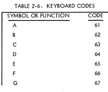
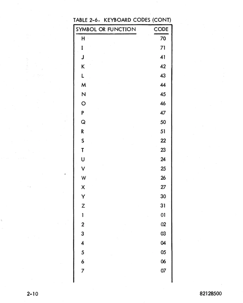
KEYBOARD CODES.
Table 2-;6
I
ists keyboard codes associated with the Display Station. Thefirst column lists the symbol and the second column
I
ists the associated code.TABLE 2-6. KEYBOARD CODES
SYMBOL OR FU NCTION CODE
A
B
C
D
E
F
G
61
62
63
64
65
66
, Operation and Programming Section II
TABLE 2-6. KEYBOARD CODES (CONT)
SYMBOL OR FUNCTION CODE
H
70I 71
J
41K 42
L 43
M
44
N 45
0 46
P 47
Q 50
R 51
S 22
T
23U 24
V
25W
26X 27
Y 30
Z 31
01
2 02
3 03
4 04
5 05
6
06
, Section II
Operation and Programming
TABLE.
2-6.
KEYBOARD CODES (CONT)
SYMBOL OR FUNCTION
CODE
8
10
9 II
0
(Zero)
12
=
13
':/;
14
~
15
%
. 16
[
17
Space
00
/
21
]
32
I
(Comma)
33
( 34
r--
35
-
36
-
(Minus)
40
1\
37
v
52
$
53
*
54t
55
+
56
>
57
+
60
<
72
,Operation and Programming Section II
TABLE 2-6. KEYBOARD CODES (CONT)
SYMBOL OR FUNCTION CODE
) 74
~ 75
•
(Parity Error) 76; 77
20
-
(Carriage Return) 101Il
(Send) 102I (Aux Send)
SECTION III
INSTALLATION AND CHECKOUT
This section contains crating and uncrating instructions, physical I imitations, power requirements, cabl ing information, cool ing requirements, environmental considerations, and mounting procedures for installation. This section a Iso contains test procedures, initial starting procedures, and checkout information.
CRATING INSTRUCTIONS.
Place the prefabricated base on a table and place a 4-foot by 8-foot section of 4-mil polyethylene over the base. With the hood removed, place the monitor unit in the base over the plastic sheet. Remove the magnetic shield from the crt and place it in a plastic bag and seal it. Now put the shield in front of the black heat sink of the deflection assembly. Cut a suitable section of polyethylene foam and place over the printed c ircu it cards on the deflection and secure the foam with filament tape to the chassis. Place a wooden form over the crt base and strap it to the chassis. Fasten the crt base to the wooden base with masking tape. Cut slots in the plastic sheeting at the four corners of the base and run copolymer strapping under the base <;It the rear of the chassis and around the chassis and base, directly under the face of the crt. Place the hood on the unit. Coil the power cord in 6-inch loops and secure with tape. Place the cord against the rear panel and pull
up the polyethylene sheet to cover the whole unit and secure with tape. Make up cardboard carton and place over monitor and base, taking care not to knock off any external controls; ie, ON/OFF/INTENSITY switch or the fuse located in the rear of the unit. Use copolymer strapping to hold cardboard carton to the base. Refer to figure 3-1 •
UNCRATING INSTRUCTIONSo
Remove all packing materials and keep them if reshipment is anticipated.
· Installation and Checkout Section III
DEFLECTION
~--ASSEM8LY
HEAT SINK
ELECTROMAGNETIC - - : - - - - SHIELD
--_DEFLECTION ASSEMBLY
:ft---
ANALOG CARDSDISPLAY --STATION
FUSE
Figure 3- 1. Display Station Interior View
and install the electromagnetic shield. The shield is in place when the end is flush with base of crt yoke. Replace crt socket. Check the fuseholder to see if it con-tains a 2-ampere slo-blo fuse.
CAUTION
Place the ON/OFF/INTENSITY control in the OFF position before connecting power to the Display Sta-tion to prevent damage to the crt phosphor.
, Section III Installation and Checkout
491 CJI-\"'LI-____
Figure 3-2. Display Station Card Location
NOTE
Refer to Section VI of this manual for card adjust-ment procedures.
(a) P,lug the 491 card (voltage regulator) into jack location J2B.
(b) Plug the 046 card (diddle ampl ifier, pulse shaper) into jack location
J1A.
(c) Plug the 044A card (vertical deflection) into jack location J1B.
(d) Plug the 044 card (horizontal deflection) into jack location J3A.
(e) Plug the 211 card (video ampl ifier) into iack location J3B.
, Installation and Checkout Section III
POWER REQUIREMENTS.
One Display Station requires 105- to 125-volt, single-phase, 1.25-ampere, 60-hertz power. The other Display Station requires 215- to 240-volt, single-phase,
o
.63-ampere I 50-hertz power.CABLING.
Table 3-1
I
ists Display Station connector pin numbers and the signal carriedon each wire. The cable consists of four coaxial
I
ines and 21 twisted-pair wires.Unl isted pin numbers are not used.
TABLE 3~ 1 • DISPLAY STATION CONNECTOR
PIN NO. SIGNAL
Data Bit 20
2 Data Bit 21
3 Data Bit 22
4 Data Bit 23
5 Horizontal {Coaxial line}
7 Vertical {Coaxial line}
8 Data Bit 24
9 Data Bit 25
10 Data Bit 26
11 Clear
12 Strobe
13 Repeat
14 Function Strobe
15 Send Index
16 Interrupt
, Section III Installation and Checkout
TABLE 3-1. DISPLAY STATION CONNECTOR (CONT)
PIN NO.
19
20
21
22
2324
25
26
27
34
38
40
COOLING REQUIREMENTS 0
,
Ground
Ground
Ground
Ground
Ground
SIGNAL
Alarm Disable
Alert Light
Attended/Unattended Light
Attended/Unattended Switch
Alert Audible Alarm
Video (Coaxial Line)
Diddle (Coaxial Line)
There are no special cooling requirements for the Display Station. It is
designed to operate at room temperature. Refer to table 1- 1 •
ENVIRONMENTAL CONSIDERATIONS.
There are no spec ial environmental conditions to consider when install ing the Display Station.
CHECKOUT 0
To start the Display Station, follow the procedures
I
isted below to ensure· Installation and Checkout Section III
,.-(a) Ensure that a 2-ampere fuseisin thefus,eholder located at the rear of
the Display Station.
(b) Ensure that the ON/OFF/INTENSITY switch is in the OFF position.
(c) Check to see that the five analog cards are in their proper locations.
(d) Apply power to the Display Station by turning the ON/OFF/
INTENSITY switch to the ON position.
(e) Rotate the ON/OFF/INTENSITY switch clockwise until the entry
marker is visible.
(f) Depress the CLEAR key to clear all data from the display memory and
SECTION IV
THEORY OF OPERATION
The Display Station is a modularized computer communication device
con-sisting of a keyboard and a crt 0 The keyboard provides a means of entering data
into the equipment and controlling its destination 0 The monitor assembly provides
a means of displaying data from the Equ ipment Controller or the data source through the Equ ipment Controller. Figure 4- 1 is a b lock diagram of Display Station func-tions. Refer to Section V for the Display Station interconnection diagram.
EQUIPMENT CONTROLLER
vlpeo
DIDDLE
VERTICAL DEFLECTION
HORIZONTAL
DEFLECTION
Figure 4-1. Display Station Block Diagl'<:Jm
MONITOR ASSEMBLY.
Deflection signals and a video signal from the Equipment Controller are the monitor deflection assembly inputs. Deflection assembly outputs vary the magnetic field of the yokes on the crt to position the crt electron beam. A high-voltage assembly generates voltages necessary for intensity control, crt post accelator, and focus and screen electrodeso A low-voltage assembly generates low-potential
, Theory of Operation Section IV
.. CATHODE RAY TUBE.
The Display Station contains a 14-inch rectangu lar, electromagnetically-deflected crt. Changing the magnetic field of a two-section yoke, located on the
neck of the crt, positions the crt beam 0 Pu Ises appl ied to the crt cathode unblank
the beam. The yoke closest to the front of the crt controls horizontal and vertical beam positioning. Horizontal signals generate a yoke current ramp during the time the crt beam makes one horizontal trace. A vertical yoke current ramp moves the crt beam down one line at the end of each horizontal trace. The yoke at the rear of the crt places a vertical sawtooth {diddle pulses} on the horizontal sweep. The two sections of the yoke are necessary because diddle pulses occur at a much higher frequency than hori"zontal and vertical signals.
LOW VOLTAGE.
The Display Station low-voltage assembly suppl ies a-c voltage to the crt filaments and d-c voltage to the high-voltage assembly, deflection assembly circuit cards, final yoke driving amplifiers, and Display Station keyboard relays. A volt-age regulator card, final amplifiers, and associated circuitry in the low-voltvolt-age
assembly regulate the
+
12-volt d-c voltage. Refer to figure 5-4.Power input to the low-voltage assembly is 120 volts, 60 hertz, 3 wire, single phase, through a 2-ampere fuse located at the rear of the Display Station and the ON/OFF switch on the right side of the Display Station. A secondary winding of the tow-voltage assembly transformer provides 6.3 volts ac for the crt
fi lame nt. A
+
16-vol t secondary wind ing provides current for the high-vol tagepower supply, keyboard relays, and
+
12-volt regulator circuitry. A+
24-voltinput, obtained with an additional secondary winding, is required for
+
12-voltregulation. The 491 voltage regulator card, final amplifiers in the deflection assembly, and associated circuitry in the low-voltage assembly regulate card voltage.
NOTE
A Display Station is available which uses a 230-volt, 50-hertz, 3-wire, single-phase power input.
HIGH VOLTAGE 0
· Section IV Theory of Operation
input power requirements (+ 12 volts dc and + 16 volts dc). An input is also received
from horizontal deflection ampl ifier card 044 in the deflection assembly. Th is signal prevents crt electron bombardment damage when the horizontal and vertical sweep signals are absent.
Figure 4-2 is a simplified representation of the high-voltage assembly. Figures 5-1 and 5-7 show more detailed illustrations.
I+--HORIZONTAL
DIFFERENTIAL AMPLIFIER
1+--+ 12 VOLTS
~
,
+ 16 VOLTS
MODIFIED
HIGH-VOLTAGE 5 KV ... VOLTAGE 10 KV RESISTOR POST ..
----
JENSEN---..
-..
CAPACITOROSCILLATOR TRANSFORMER DOUBLER FILTER ACCELERAT
L
FOCUSINTENSITY
SCREEN GRID
Figure 4-2. High-Voltage Assembly Simplified Block Diagram
OR
The + 16 volts dc provides power necessary to begin and sustain oscillations
in the Jensen oscillator (Rl, Ql, Q2, T2, R2, el, and R4). Oscillations are
maintained by Q3 conduction and the subsequent charging of capacitor C? to a
level of approximately +8 v.olt~~ Th is vol tage is fel t on Q 1 and Q2/collectors
through T2 primary. This results in Ql and Q2 being forward biased with a resulting
current flow being felt by saturable transformer T10 With the transformer being ,
wired in a positive feedback manner, the collapsing field (upon reaching saturation)
wi
II
resuI
t in driv ing Q2 into conduction and shu tting Q 1 off 0 The Jensen oscilla-tor, therefore, is kept in operation by the building up and collapsing of the field
around T2 and transistors Ql and Q2 alternately conducting and not conducting 0
The oscillations contil'.lue until capacitor C2 is discharged,.,
A
balance pot. adiustsconduction balance for transistors Ql and Q2j a feedback pot 0 assures proper
, Theory of Operation Section IV
Jensen oscillator output is applied to high-voltage transformer T2. Current passes through T2 primary each time Q 1 or Q2 conducts and thereby induces 5000 volts into the secondary winding. The secondary is tapped to provide filament voltages for V1 and V2 (part of the voltage doubler circuit), screen-grid and focus voltages, and the input signal for the differential amplifier.
The 550 volts tapped off the secondary is appl ied directly to the crt for screen grid voltage, and through a series of resistors (one of which is adjustable) for focus control. Focus vol tage is adjustab Ie for a range of 60 to 340 vol ts by R 16.
Voltage doubling is accomplished by V1, V2, R12, R13, C5, and C7. R19, C7, and capacitance of the crt coating filter the 10-kv output. R 14 is a bleeder resistor to discharge C7 when Display Station power is turned off. As stated pre-viously, the 5000-volt input to the voltage doubler is taken from the secondary of T2. This voltage (in the form of a sine wave) is felt at capacitor C5. Each cycle of the 5-kv signal builds up a constant voltage reference line until 5 kv is reached (figure 4-3).
T2 SECONDARY 0 VOLT
V2 ANODE
'+10 KV - - - -+ 7.5 KV - - -
-+ 5 KV - - -
-+2.5 KV -o VOLT
-·2..5 KV' - - -
--5 KV - - -
--7.5 KV - - - . - - -
--10 KV - - - .
-Figure 4-30 Voltage Doubling Steps
A 5-kv signal "rides" on the 5-kv reference line. This stepping action is
accomplished by C5, the resistance in the core of transformer T2, and diode V1 0
· Section IV Theory of Operation
superimposed signal 0 R19 and C7 filter out ripple and provide the crt post
accelera-tor with a constant 1 O-kv source.
A 3-turn winding on transformer T2 senses the flux change of the transformer and feeds this change into the differential amplifier. The flux will vary as the load on the supply changes. The change induces vol tage into the differential ampl ifier. The amplifier senses this voltage change and, in turn, increases or decreases supply vol tage to maintain a constant 10-kv output to the post accelerator.
The induced voltage is half-wave rectified by CR5 and filtered by C4.
Potentiometer R 11 varies th is voltage to the base of Q60 Th is potentiometer is the high-voltage adjustmento Refer to Section VI to make this adjustmento
The differential ampl ifier consists of transistors Q5 and Q6. CR4 maintains a constant 2.4 volts to base of Q5. Q6 conduction determines Q5 emitter voltage.
As
Q6 conducts more, the voltage drop across R10 results in increasing emitter/basebias of Q5. The resulting decrease in conduction of Q5 reduces the voltage drop across R9. A direct relationship, then, is established between the 3-turn winding of T2 and the voltage drop across R9.
The voltage dropped across R9 controls Q4 conduction.
As
voltage acrossR9 increases, output of Q3 decreases resulting in a less positive potential on
capa-citor C2.
As
stated previously, in the explanation of the Jensen oscillator, thecharge on C2 determines conduction of oscillator transistors Q1 and Q2.
Loss of horizontal or vertical signals from the Equipment Controller results
in crt damage through electron bombardment on the crt face 0 Th is happens if high
voltage is maintained o R6, R7, C3, __ CR2, and CR3 are employed to prevent this.
The horizontal amplifier provides a negative signal to CR3 0 Signal amplitude is sufficient to negatively charge C3. The negative potential provides a reverse bias condition for CR2.
Losing the horizontal signal removes the reverse bias condition of CR2 0
Removal of this bias drives Q~ to saturation, cuts off 'Q3, and removes oscillator
power 0
DEFLECTION 0
The deflection assembly (figure 5-3) in the Display Station controls crt beam
positioning and unblanking. It contains amplifiers for amplifying and shaping video,
horizontal, vertical, and diddle signals received from the Equipment Controller. It
,Theory of Operation Section
IV
044
Card, Horizontal Deflection Amplifier.The
044
card is located in jack location J3A. A general description andtheory of operation follow. Refer to figure
4-4.
The horizontal amplifier controls the horizontal deflection coi I driver which allows a linear sawtooth of current to flow through the horizontal deflection coils. One sawtooth of current through the deflection coi Is moves the electron beam from the left to right on the display monitor screen. The electron beam returns to the
left side of the screen duri ng sawtooth retrace. The
044
card contai ns horizontalgain and linearity controls for manual adjustment of the current waveform. Pro-cedures for adjusting these controls are in Section VI. The initial sawtooth
wave-form is supplied to the
044
card from a ramp generator in the Equipment Controller.The input at pin 2 is a sawtooth wave with a range of approximately
5
volts.This sawtooth at the emitter of Q1 i~ amplified and applied to the base of Q2
caus-i ng emcaus-i tter collector current to caus-increase at a ramp rate. Q2 collector current flowcaus-i ng through R13 (horizontal gain control) develops a positive ramp voltage at test point A. Negative feedback from the Q2 collector to the Q1 emitter tends to fix the two-stage amplifier gain.
Potentiometer R13 output is coupled into Q3 base, amplified and inverted, and direct coupled to Q6 base from Q3 collector. Q6 is an emitter follower which drives the hori zonta I deflecti on coi I driver transi stor in the deflecti on assembly.
Pin
5
inputs a feedback sawtooth voltage to the044
card from the deflection assembly.The feedback is required to produce a nonlinear voltage ramp which is
needed to give a linear current ramp through the deflection coi I. Potentiometer R16
determi nes the effect feedback wi
II
have on the linearity of the output voltagerange.
A trapezoid voltage waveform across the deflecti on coi Is is requi red to duce a linear sawtooth of current through the coi Is. The required trapezoid is pro-duced at Q6 emi tter. Q6 is cut off just before the end of retrace and begi ns to conduct just after the trace begins.
001
a~
~ ro
~ 0
00 +12V :::!'.
'8
a"~,
, , "~
,t
I~
~ !5I003l08 C3 410Uf !OV Q2 ~.
2 I
47 e\W I'"
t
~
AI!i-2t
C4..L+ 15UF
1
lOV RI5 Z20 .03W11. +
• 06
R22 68 IW +CIO
~
-15UF 20V 10• () 9
R23
~ • .!\IV 04
~£
C9 410
:!!I
CO, C
lOY II(
l5W I
4'"
"gy
C7LF1·
ISUF ~~(--- 05~
•
.J:lo.
I
~
I
0-0:::0»»fT1
:::0:::0<
0-1·
-IZO)
- < 0 ,
-0. 0)
fT1 ~
0 0 ~g 0 w Ul~ fT1~ :::0
rn
»t
-I
::r:
0
.,
'11
C~
N 0
:::s
r+
OJ ~. O~
< CJ A)
....
A) n r+ 0 :::s ~ "tJ....
A)..,
,2.0 V~~Q~~~C?~O
=4."
'P
~~o~
J~
9':"
~P~~~ ~~,:,~
"~O-Q~
p~
-0.'
~~
l>
9
1co. +~ ~ ~---p
-t ::r ro o ~ o ""1"t
o
-0 roa
(X)
'"
-~ 01 o o::n
CO C @ ..J:Io. I ..J:Io.tl
n-,,::::o»»m
::::0<
;:v
-f ·
OZ~
-f0»
-<.
-u-.o.m8
08
t~
::J: 0 ::!. N 0 :::J..
Q0 (D ~ (D n :!.
g
t
~-.
~ (D.,
~
-RZ IK QI Q2 51003108 C3 ~ 410UF 50V R3 210C4 1.+
1=1
'11
c:
+
N" OUi < "::" R7 +12V ~---1----~06 R22 68 IW 20V
~
:~I~F 10• 09
R23
~ , N\J' 04
C9 410
~~(---O~ 05
2:) V
UK
C7 ~
6OlI"I
6V~£
-=
~~O~'~,-~~ C?~o
I I
I
"
,~~~o
"
. I
,
9.
w'F>
~
•
I
9-~'-Y~~ ~ ~~.
I=f
-
p' '"
"
0
. 9'
~ ~p ~
"
I..
,()
-~ ~.
~ ~d •• p
9'_
c.
+P
~ =L c.op
V) (D o
-
<)" :::J<
-f
~ (D 0.,
"< 0...,
0
].,
Q"
, The,ory of Operation Section IV
044A Card, Vertical Deflection Amplifier.
The 044A card is located in jack location
J
1 B. A general description andtheory of operation follow. Refer to figure 4-5.
The vertical amplifier controls the vertical deflection coi
I
driver whichallows a step ramp current to flow through vertical deflection coilso The ramp current through the coi Is moves the electron beam down one line at the end of each horizontal line. After a full page, the electron beam repositions at the top of the crt and is ready to trace the next frame. A vertical step current ramp from the Equipment Controller is the 044A card input. The card output drives the ver-tical deflection coi I driver which allows current to flow through the verver-tical deflec-tion coi Is.
Pin 2 input is a sawtooth wave of approximately 5-volt ampl itude coupled'
to the emitter of Ql.
As
each step makes Ql emitter less positive, Ql conductsmore and dutputs an ampl ified staircase causing Q2 emitter collector current to increase and develop a positive staircase voltage across amplitude control R 13 at test point A. Negative feedback from Q2 collector to the Q 1 emitter tends to keep the vertical step ramp output amplhude constant, thereby compensating for input ramp amplitude variations- Transistor Q3 amplifies and inverts the step ramp and drives emitter follower Q6. Q6 emitter is the 044A card output at pin 6 and is direct coupled to the vertical deflection coil driver transistor in the deflection
assembly. ·
The circuit configuration is comprised of Q3, Q4, and Q5. A different amplifier maintains vertical linearity. Q5 base receives a feedback voltage from the deflection assembly. This feedback produces a nonli near voltage ramp which provides a linear current ramp through the deflection coi I. Potentiometer R16 'determines the effect feedback will have on output voltage linearity.
Potenti-ometer R13 is the vertical gain control.
~I
.~
~ m
~ 0
00 +12V :!".
8·
"~,
,
T T T~
T~
I~
"'T1
cO·
c..
m ~ I~
R2 IK Q2 C51+ 15uFI
20VI
51003109I
I ~( ~4 ~ T PA EO) , 1500UUF 200V
220
R9 ~JlJF
€6UF
~1 t---31+ e VVV' ;
6V 6V ~ RII RI2 10K
CW
RII;
5.~~.:...t
__ --,n-u:::o
»»fT1
:::0:::0<
a --t •
-iZOJ
-<0'--u. OJ
fTI
'"
0 0 ~g » 0 ~ 0 (/)1\.) fTI :::0 fTI (I)»
< 10.,
r+ n DI CJ 10 ... 10 n r+ 0 ::J»
3 "0 ...~117K 15W'
4% I
rlf---C:
+ ---o~
N ....
<
RIB 100
• 06
R22 68 IW 20V
~
~I~I~F 10 ~--~~---~n9 R23 4CIO 470
--+"!C 1 5 U \ F - - - 05
20V
~ ~O=~f.~I~~1
SR
~~?
y
9'"
'P
~
mu ( )
1l( ·
~
.0
P8~A
f.lll
n
1'1
~~~S%~Vl~ l~
u(Q
9'
C~
+F:>
Q~'
.
0/,
c=:::G3=
J
U IT
l:l~
J
I~O'?
c:-~~~~F
.. ' ..~
__-~:
~ ~c~ __ J:-J_ ----~
__ ~ __ ~ C [ ., 5") c [., l=")
-4 :::r m o ~ o
....,
o
~ 10
.,
~ c--£~__
J:>
c[~~ __ J~ c [. co_j-=->
~m
I
"
-'" ~---~--- ----
a
~
00
'"
...
~ 01 a a ::!l (Q C..,
CD ~ I 011
I
~ I ()-o:::o»~<
:::0 -t •Oz»
-tO~-<.
-0-.0 ma a a 0 ° ~~ ~'" ~<
CD ..,-
n 0 0CD ..., CD n
-0 ::s»
3 \J -M CD..,
-=-R2 IK RI2 10K Q2 C4 cwRI3
~
2t
IK
t5W I 4%
C5 1.+
'5uF
I
20V R3 220 60UF 6VOU
R~ ~ ~YUTb~
, .
,~
" []:~- cs
-I
..
~~~~
"'~~ o~
~~~~~~~~~
9"
CII-p
-=-R7
+12V
• 06
R22 68 IW 20V
~
~I~I~F 10 9~ • ./\IV' 04
C8 ~
60lFI 6V
2..7K
-=-R\8100
CIO 470
~(
IOUF 05
25V
11
+12Vtil
I CD
n
-o·
::l-<
-t :::r CD o .., o ...,o
\J CD .., o-o·
c..v, Theory of Operation Section
IV
046 Card, Diddle Amplifier and Pulse Shaper.
The 046 card is located in jack location J1A. A general description and theory of operation follow. Refer to figure 4-6.
The diddle amplifier shapes, peaks, and integrates a square waveform from the Equipment Controller and drives a didd Ie yoke driver transistor. The diddle yoke driver forces a sawtooth current to flow through the diddle yoke coi I every 2.4 microseconds. As a result, a sawtooth waveform is impressed on each horizon-tal line every 2.4 microseconds as the electron beam moves across the crt.
The input to pin 3 of the 046 diddle amplifier card from the Equipment Controller is a positive-going signal with a range of approximately 5 volts. This input pulse causes Q4 to alternately conduct more and less. The output of Q4 is applied to Q1 which causes Q1 to alternately conduct more or less. Thus, the actions of Q4 and Q1 cause the input signal to be amplified.
Emitter collector current in Q1 through R18 develops a positive-going pulse on the base of Q5. Q5 then is forward biased into conduction and develops a positive-going square wave output on its collector. The output ofQ5 is coupled into an integrator circuit comprised of R6, R7, R14, and C2. This integrator cir-cuit shapes the square wave into a sawtooth waveform which drives the next amplifier transistor, Q6. Potentiometer R14 is a phase control provided for manual adjustment of the sawtooth waveform. Video unblanking pulses are timed to occur during the rise time of the diddle sawtooth waveform. The diddle phase control adjusts the slope of the diddle waveform to ensure unblanking at the proper time. This is nec-essary to produce symbols of the proper shape and proportion.
Current amplifier Q6 drives Q20 Q2, in turn, amplifies the sawtooth wave and drives output transistor ·Q3. Circuits CR1, R24 and CR2, R25 are dampening circuits which prevent negative signals from appearing on the bases of Q5 and Q3, respectively.
A dampening network comprised of C5 and R12 diminishes oscillations in the primary of output transformer T1. The output is taken from pi n 12 of the 046 card. This sawtooth current waveform output is required to drive the didd Ie yoke driver transistor. A diddle amplitude control, mounted on the deflection assembly chassis, provides verti cal symbol si ze. This control assoc iated with the diddle yoke driver transistor which is located on a heat sink on the same chassis.
Section
IV
'"
!l! ...
'" '" ;: ... '" .,N "'.
..
.. N e_ .~ ~ 0..> . ui2 ~HI' N 0 ~.
...-r
T T~'"
r
5!
- 0 . 0 0
uo-n
.~~
-r
N~
I
..
tJ
0
:; 10.> :..,
0'"
~~&
~.l ~
U I .. i~!
0 ~
Ii N
f----@~
~~&
,
.. ':!5~
U - ; N ~~
.n~~ U:;N
~@~.
......
~ .....
,., 0 0....
"' ...~?! (;
'" ~~ ""~ ~ t::~~
--"' ... "'
..
~~ ... '"
1 ..
:!::
...
e
..
~ c)
""
0
¥s
... '"
N;)O
U!!N
" +
....
...
"' ...
"'",
-~tIt U~N
.. 0 " , , , "
",
..
A
..
..
"' ...
"''''
...
:~
...
:.'" ;)0 0 0 0 N -UN
I
..
; ) " ,
;)0 ... 00 N_ UN ----it.---N N", "'-AA ~!
0 ..
~~
, A
-
'"C N N
~=
..
..
N ...
'"
..
U ,.,
0
.'"
_ ..."'. A
I
~o---·~ ...
Theory of Operation
o
idd Ie Amp I ifier and Pu Ise ShuperREV. A/B .
PART NO.
90000405Section IV
~ •
•
- N N N ~N::::
:1
!:!i
> c ...
~ +
~ii
~=.
11:-•• 11:==~
• ... 11:-' • 2II: on
•
.
~ 11:. -2 11: ...I
u!!2".
+ ( > N+
HI
I!
•
;!!~I
til N~c-§
IIQtn2
u-+
!! ~
"
(§)
G!:)~ o~~~~r ~~~~~
O~Q 88~
~
"
~"~~
.
~ ~ ~ ~~
A~~~
8
~:. ':~3
Writing
Ampl
ifierREV.
sic
, Theory of Operation Section IV
211 Card, Video Ampl ifier.
The 211 card is located in jack location J3B. A general description and theory of operation follow. Refer to figure 4-7 •
The video ampl ifier unblanks the crt to produce visible symbols at the proper time. Video unblank pulses are fed into the video ampl ifier from the Equipment Controller. The video ampl ifier shapes, ampl ifies and appl ies unblank pulses to the crt to unblank the electron beam for 100 nanoseconds each pulse.
A train of video pulses for each symbol transmits from the Equipment Con-troller to video ampl ifier card input pin 2. The pulses are negative -goi ng
100-nanosecond pulses. Emitter follower transistor Q3 is driven by Q 1 and Q2, a grounded base configuration. R3 and C2 fi Iter the supply voltage for the preampl ifier section. This el iminates regenerative feedback. The preampl ifier has a fixed gain which is set at a high value and causes Q2 to be driven into saturation (lII'flat tops'· video pulses) •
The output of Q2 is a positive video pulse. Emitter follower Q3 is driven by the positive-going pulse from Q2. Q3 output is a positive pulse across R15 at test point A. Transistor Q4 is used as a pulse peaker. Because of circuit and stray capacitance, the leading edge of high frequencies of the pulse attenuates causing slow rise time. Capacitor C3 passes high frequencies to Q5 base and attenuates lows. Due to bias conditions on Q4 and Q5, a pulse in excess of 6 volts placed on the base of Q4 allows Q4 to conduct. Q4 conduction results in the cutting off of Q5 which causes a positive voltage pulse on the collector of Q5. The circuit of Q4 and Q5 is a Schmitt Trigger configuration.
At horizontal retrace time, the horizontal deflection coil field collapses. This collapsing field induces a voltage of negative polarity that is connected to CR4 cathode. Therefore, CR4 is forward biased and conducts charging C9 and C10
negative with respect to ground. CR3 is a 16-vol t Zener diode which clamps the
charge on C9 at negative 16 volts. This negative 16 volts on the emitter of Q6 and positive 12-volt collector supply provide 28 volts emitter collector supply voltage on transistor Q6. The positive video pulse on the base of Q6 causes this transistor to conduct producing a 28-volt negative pulse at output pin 11. The negative video pulse connects to the crt cathode and unblanks the electron beam for 100
nanoseconds.
Pin 9 connects diode CR 1 to the center arm of the intensity control poten-tiometer. CR 1 clamps the crt bias at the voltage determined by the position of the bias potentiometer. Pin 10 connects the 2.7-megohm resistor to the intensity con-trol voltage divider and provides a high impedance signal path from cathode to
ex> "-> "-> ex> 01 o o ~ cc c:
.,
(]) ~ I ' l ()-o;::o» »m
; : : 0 < ;::0 -i •CJZ~ -iO~
-<
-0'0 m O o o ~~" ' 0
. . CO
<
a:
ro o
»
3 -c :;;('I) ...,
@
O~80"~: ~ ~~
~ ~ ~
0 "
~n~o~~~ ~'0"~ ~~
~~~~
:
~ ~O
;I~~f~: ~~~
.,..12"
8
r
+12V15 V') ('I) o
....
o :J<:
-i ::r ('I) o ..., '<o
..,.,
o
~..,
o
· Theory of Operation Section IV
49] Card, Voltage Regulator.
The 49] card is located in jack location J2B. A general description and theory of operation follow. Refer to figure 4-80
The Display Station requires deflection currents varying from no load condi-tions to full load condicondi-tions of up to approximately 4 amperes. Deflection currents of this magnitude normally cause unregulated low-voltage power supply to decrease when load current increases and increase when load current decreases. The 49] card (+ ] 2-volt regulator) is designed to satisfy the changing current requirements of the Display Station and to maintain the constant +]2 voltage required for proper biasing and operation of the vertical deflection ampl ifier ,horizontal deflection ampl ifier, diddle ampl ifier and pulse shaper, and video amplifier.
Transistor Q2* is a series or current regulator. Q] * controls the emitter-to-collector current of Q2. Q] provides forward bias for Q 1. Transistors Q2, Q3, and Q4 amplify changes in voltage developed across voltage divider R6, R9, and R]4. Potentiometer R9 adjusts the forward bias on Q4 for proper voltage output. The ampl ified change in voltage controls Q2 emitter collector current which is also load current. Resistors R7 and R8 provide a minimum load current through Q2. When load current increases, supply voltage tends to decrease.
This decrease in voltage across R9 appears on Q4 base. Transistor Q4 requires positive voltage on its emitter. A decrease or less positive base voltage forwards bias Q4 causing emitter collector current to increase. Increased current through R5 emitter resistor causes a voltage drop (less positive) on Q3 emitter. Zener diode CR2 maintains a + 5 .6-volt bias on Q3 base. The less positive voltage on Q3 emitter causes Q3 to conduct less. Voltage across R ]3, developed by Q3
collector current, becomes less positive 0 Q 2 conducts less. Q2 collector voltage
increases, biasing Q1 in a positive direction. An increase in Q] emitter current develops a more positive bias voltage across R 12 which, in turn, lets Q2 conduct more current to the load which compensates for increased load current and allows output voltage to remain at a constant + 12 volts regulated.