IJEDR1601022
International Journal of Engineering Development and Research (www.ijedr.org)128
Modeling and Analysis of Frame Structure of PCB
Drilling Machine
1Chirag R Prajapati, 2Prof.Dhaval P Patel, 3 Mr..K.S.Parmar 1ME Student, 2Assistant Professor, 3Lecturer
123Mechanical Engineering Department,
12Gandhinagar Institute of Technology, Moti Bhoyan, 3R.C.Technical Institute, Ahmedabad
________________________________________________________________________________________________________
Abstract – Drilling Machines is used to make a hole and it is widely used in industry. Other processes for producing holes are punching and various advanced machining processes. The cost of holes making is one of the highest machining costs. There are several types of drilling which are gun drilling, twist drill, and trepanning. The most common drill is the conventional twist drill. Many products used drilling as their major processes. Without drilling operation, the work cannot be done successfully. Drilling operation has been used in many sectors of industries such as automotive, piping, major industries also minor industries. The importance of drilling is increase by time because of the modern world and the used of high speed product in our life. Drilling operation also used in electronic industries. One of the examples is to produce a hole on a circuit board. Even as tiny as a ants, it also need to use drilling operation. That show us how important is drilling operation. The main objective of research paper is to reduce vibration of frame structure of PCB drilling machine. By applying propose material selection for structure and optimize dimension of structure from data of present PCB drilling machine and change geometry and material of structure.
Index Terms – PCB Drilling Machine, Structure, Vibration, Material, Modeling, Analysis.
________________________________________________________________________________________________________
I.INTRODUCTION
Micro drilling process is used to produce a small highly accurate hole which is a common requirement across large number of industries and applications. Industries and applications that require huge volumetric production, the drilling time and the finishing of the hole, rivals the cost of the process. So an intensive study of the machining process is required to make the production economical. Drilling refers to a metal removal process which removes a circular cross section from the work piece. The drill bit which is a multipoint cutting tool in most cases is pressed against the material and rotated which cuts of chip from the material and this result in the formation of hole. Drilled holes are characterized by their sharp edge on the entrance side and the presence of burrs on the exit side. Helical feed marks are also present inside the hole. Drilling also affects the mechanical properties of the material. So in order to find out the local circularity error, the use of optical microscope (SEM) is required. The forces acting during the operation is measured using dynamometer. The work piece used is copper coated PCB. Drilling operation is performed on a CNC machine by coding an appropriate program. The drill bit used in this case has a diameter of 1 mm. The burr formed during the drilling operation must also be examined and analyzed in order to reduce it in future operation.
II.PCB DRILL MECH SS300
IJEDR1601022
International Journal of Engineering Development and Research (www.ijedr.org)129
Aditi Engineering Works introduces PCB Drill Mech SS300 of fully intergraded intelligent PCB Drill system. The PCB Drill Mech SS300 is unique in its combination of Speed, Accuracy, Simplicity and Reliability. PCB Drill Mech SS300 offers the latest in PCB Drilling Systems at cost effective price.SYSTEM FEATURES
1. Rigid machined main structure with high precision assembly provides stable structure, good shock absorption, smooth running and high rigidity, assuring high precision.
2. Adopt imported ball screw and Linear Motion guide. 3. 400W Fuji Servo Motor-Made in Japan
4. PC based Software-PCB Mech Drill 12 5. 800W spindle and 24000 RPM.
6. Gerber file support. 7. Data path optimization.
TECHNICAL DATA
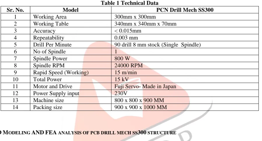
Table 1 Technical Data
Sr. No. Model PCN Drill Mech SS300
1 Working Area 300mm x 300mm
2 Working Table 340mm x 340mm x 70mm
3 Accuracy < 0.015mm
4 Repeatability 0.003 mm
5 Drill Per Minute 90 drill 8 mm stock (Single Spindle)
6 No of Spindle 1
7 Spindle Power 800 W
8 Spindle RPM 24000 RPM
9 Rapid Speed (Working) 15 m/min
10 Total Power 15 kV
11 Motor and Drive Fuji Servo- Made in Japan
12 Power Supply input 230V
13 Machine size 800 x 800 x 900 MM
14 Packing size 900 x 900 x 1000 MM
III.CAD MODELING AND FEA ANALYSIS OF PCB DRILL MECH SS300 STRUCTURE
Turn off visibility of nonessential components. Access the parts we need and update graphics faster. Use design representations. Create design representations that highlight specific design problems or assembly subsystems, and apply them when opening the assembly model. Turn off part adaptivity. After we size components, turn off adaptivity to speed up solutions and prevent accidental changes. Assign different colors to components. Select colors from the Color list on the Standard toolbar. Use the browser to find components. Point to component in the browser to highlight in the graphics window.Use color to identify components groups. Using attributes, find components in specific subsystems or from specific vendors and color-code them in named representations.
IJEDR1601022
International Journal of Engineering Development and Research (www.ijedr.org)130
The structures of PCN Drill Mech SS 300 is divided in to two part one for X-axis which axis for work piece like PCB and another for Y-axis for movement of Z-axis which having a spindle or tool for 2 D hole cutting.Fig.3 Detail view drawing Y-axis of PCB Drill Mech SS 300 Structure
Fig.2 and 3 are reflected detail drawing of both structure of X and Y axis respectively. Using part features creates all components of structure. All assemblies are created using various components (part) by constrained there relative motion. Using part modeling environment to create structure.
First to make geometry of standard section pipe with respect their practical data to measure thickness of plate and amount of extruded part by using extrude command in feature operation.
Further using new sketch on base extruded component and draw sketch on existing extruded feature to identifying model width. As shown in Figure 4 to 7, there are different orientations of PCB Drill Mech SS 300 Structure such as isometric view, front view, top view and side view.
IJEDR1601022
International Journal of Engineering Development and Research (www.ijedr.org)131
Fig.5 Front view of PCB Drill Mech SS 300 StructureFig.6 Top view of PCB Drill Mech SS 300 Structure
IJEDR1601022
International Journal of Engineering Development and Research (www.ijedr.org)132
STRUCTURAL ANALYSIS OF PCB DRILL MECH SS 300 STRUCTUREStep-1 Pre-processing
1) First Prepare Assembly in Solidworks 2015.
Fig. 8 Geometry of PCB Drill Mech SS 300 Structure using static analysis 2) Check the Geometry for Meshing.
3) Apply Material for Each Component.
Table 2 1080 Mild Steel Material Properties Structure Material used Young
Modulus (Gpa)
Yield Strength
(Mpa)
Poisions Ratio
Density (Kg/m3)
PCB Drill Mech SS 300 Structure
1080 Mild Steel 210 550 0.266 7860
4) Create mesh.
Solid mesh (Jacobian Point : 4 Point) which is programme generated. Fine Meshing is apply
No. of Nodes:- 150067 No. of Elements:- 91257
Fig. 9 Meshing of PCB Drill Mech SS 300 Structure using static analysis 5) Define Boundry condition
IJEDR1601022
International Journal of Engineering Development and Research (www.ijedr.org)133
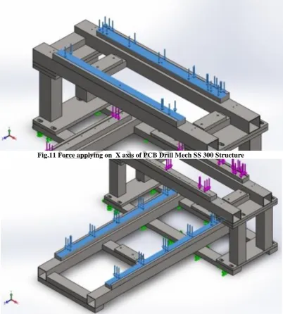
Fig. 10 Boundary condition of Sw PCB Drill Mech SS 300 Structure using static analysisApply Force Force magnitude on swing X-axis is 270N.
Force magnitude on swing Y-axis is 350N.
Fig.11 Force applying on X axis of PCB Drill Mech SS 300 Structure
IJEDR1601022
International Journal of Engineering Development and Research (www.ijedr.org)134
Results of AnalysisEquivalent Stress for static analysis
Name Type Min Max
Stress1 VON: von Mises Stress 302.045 N/m^2 Node: 73617
8.38338e+006 N/m^2 Node: 21602
AES-PCB-DOUBL-Static 1-Stress-Stress1
Fig.13 Equivalent Stress analysis of PCB Drill Mech SS 300 Structure Displacement
Name Type Min Max
Displacement1 URES: Resultant Displacement 0 mm
Node: 67138
0.0719179 mm Node: 76716
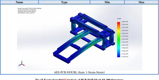
AES-PCB-DOUBL-Static 1-Displacement-Displacement1 Fig.14 Displacement of PCB Drill Mech SS 300 Structure Equivalent Strain
Name Type Min Max
Strain1 ESTRN: Equivalent Strain 4.76439e-010
Element: 13195
IJEDR1601022
International Journal of Engineering Development and Research (www.ijedr.org)135
Name Type Min Max
AES-PCB-DOUBL-Static 1-Strain-Strain1
Fig.15 Equivalent Stress analysis of PCB Drill Mech SS 300 Structure Table 3 Result
Material Von mises stress (N/m2) Strain Displacement(mm)
1080 Mild Steel 8.383 X 10⁶ 3.039 X 10⁻⁵ 0.0719
IV.ACKNOWLEDGMENT
It is indeed a great pleasure for me to express my sincere gratitude to those who have always helped me for this dissertation work. I am extremely thankful to my thesis guide Asst. Prof. Dhaval P Patel, Asst. professor in Mechanical Engineering Department, Gandhinagar Institute of Technology, Moti Bhoyan and Mr. K.S.Paramar, Lecturer in Mechanical Engineering Department, R.C. Technical Institute, Ahmedabad are valuable guidance, motivation, cooperation, constant support with encouraging attitude at all stages of my work. I am highly obliged to him for his constructive criticism and valuable suggestions, which helped me to present the scientific results in an efficient and effective manner in this research.
V.CONCLUSION
By using practical data of PCB Drill Mech SS 300 structure, prepared 3D CAD model for Finite Element Analysis in Solid Works 2015. From analysis result find value of von mises stress, strain and displacement (deflection) for optimize structure in strength and cost.
REFERENCES
PAPERS
[1] Ranadhir R Landge, Dr. Atul B Borade, “A review on Optimization of material removal rate in micro-drilling process”, AIJRSTEM 15-171, 2015.
[2] Shaikh Noor Farooque, Ansari Mohammed Faizan, Javed Shaikh, Pragati Pal, “Automated PCB Drilling Machine With Efficient Path Planning”, International Journal of Advanced Research in Computer and Communication Engineering Vol. 4, Issue 4, April 2015.
[3] Norhaizat Omar, Eng Chieh Ong, Asrul Adam, “ An Experimental Study of the Application of Gravitational Search Algorithm in Solving Route Optimization Problem for Holes Drilling Process”, International Conference Recent treads in Engineering & Technology (ICRET’2014), Feb 13-14, 2014 Batam (Indonesia).
[4] P.L.S.C Alwis, A.S Premarathna, Y.P Fonseka, S.M Samarasinghe, J.V. Wijayakulasooriya, “Automated Printed Circuit Board (PCB) Drilling Machine With Efficient Path Planning” ,SAITM Research Symposium on Engineering Advancements 2014.
[5] N. Balasubramanyam and Prof. Smt. G. Prasanthiy, “Design and Fabrication of an Automatic PC-Based Drilling Machine”, HCTL Open IJTIR, Volume 7, January 2014.
[6] Gautam Jodh , Piyush Sirsat, Nagnath Kakde, Sandeep Lutade , “Design of low Cost CNC Drilling Machine”, International Journal of Engineering Research and General Science Volume 2, Issue 2, Feb-Mar 2014.
IJEDR1601022
International Journal of Engineering Development and Research (www.ijedr.org)136
[8] G.Niranjan, A.Chandini, P.Mamatha, “Automated Drilling Machine with Depth Controllability”, International Journalof Science and Engineering Applications Volume 2 Issue 4, 2013.
[9] Feida Ma, Changtao Cai, Liangjin Cai, Jingxing Qi, “Design and Analysis for the Y-axis Linking Part of PCB Drilling Machine”, TELKOMNIKA, Vol. 11, No. 4, April 2013, pp. 1916~1923.
[10] Dr. K.K.Gupta, Prof. Tapan Jain, Manish Deshmukh, “Optimization of Process Parameters in High RPM Micro Drilling Machine”, Internation Journal of Innovations in Engineering and Technology, Vol.2, Issue 2, April 2013.
[11] Mohd Muzafar Ismail, Mohd Azlishah Othman, Hamzah Asyrani Sulaiman, “Route Planning Analysis in Holes Drilling Process Using Magnetic Optimization Algorithm for Electronic Manufacturing Sector”, World Applied Sciences Journal 21(Special Issue of Engineering and Technology): 91-97, 2013.
[12] Liang-jin Cai, Chang-tao Cai, Fei-Da Mac, “Analysis of Z-axis Rigid of PCB CNC Drilling Machines”, TELKOMNIKA Indonesian Journal of Electrical Engineering
Vol.10, No.6, October 2012, pp. 1409~1414.
[13] Metin Salihmuhsin, Sabit Baba, Ahmet Serdar Yilmaz, Mustafa Sekkeli, “Design and Implementation of an Automated PCB Drawing and Drilling System”, International Journal of Engineering Research and Development, Vol.4, No.2, June 2012.
[14] Abdhesh Kumar and Prof. Praveen Pachauri, “Optimization Drilling Sequence by Genetic Algorithm”, International Journal of Scientific and Research Publications, Volume 2, Issue 9, September 2012.
[15] Azlan Abdul Rahmanand Azuddin Mamat, “Effect of Machining Parameters on Hole Quality of Micro Drilling for Brass”, Modern Applied Science, Vol.3, No.5, 2009.
[16] H. Ferdinando, I. N. Sandjaja, G. Sanjaya, “Automatic Drilling Machine for Printed Circuit Board”.
[17] Hidehito Watanabe, Hideo Tsuzaka, Masami Masuda, “Micro Drilling For Printed Circuit Boards –Influence of Run-Out of Micro Drilling on Hole Quality”.
[18] THK Ball Screw General Catalog. Preload p.705. [19] http://en.wikipedia.org/wiki/Drilling
[20] Metal cutting technical guide (E) Drilling