IJEDR1603141
International Journal of Engineering Development and Research (www.ijedr.org)870
Analysis and optimization of Centrifugal Blower by
using FEA
1Kesare Sunil Vikas, 2Prof. Swami M. C. 1ME student, 2Assistant professor,
1,2Mechanical Department,
1,2M.S. Bidve college of Engineering Latur/Swami Ramanand Teerth Marathwada University, Nanded, Maharashtra,,India ________________________________________________________________________________________________________
Abstract–-Blowers are one of the types of turbo machinery which are used to move air continuously with in slight increase
in static pressure. Blowers are widely used in industrial and commercial applications from shop ventilation to material handling, boiler applications to some of the vehicle cooling systems. As per the discussion with concern persons of Food industries primarily fruit juice producing company. It is found that they are facing many problems regarding centrifugal blower. They are using centrifugal blower for ventilation purpose, also they are using blower to maintain the temperature of food storages (Pulp storage).The present centrifugal blower is made up of from M.S. material here corrosion is a major problem. The ingredients of the same are mixing with fruit pulps, which are harmful; also weight of the present blower is high. This paper gives the solution to above problems by optimization of centrifugal blower impeller by static and modal analysis using FEA for the material MS, SS.SS304L
Index Terms - Analysis, Optimization, Blower impeller, MS, SS, SS304L
________________________________________________________________________________________________________
I. INTRODUCTION
Blowers are widely used in industrial and commercial applications from shop ventilation to material handling, boiler applications to some of the vehicle cooling systems. The performance of the fan system may range from free air to several cfm (cubic feet per min.).
IJEDR1603141
International Journal of Engineering Development and Research (www.ijedr.org)871
II.LITERATURE REVIEW[1] Static and Dynamic Analysis of a Centrifugal Blower Using FeaVeeranjaneyulu Itha1, T.B.S.Rao2, International Journal of Engineering Research & Technology (IJERT) Vol. 1 Issue 8, October - 2012 ISSN: 2278-0181, pp. 1-11.
In this project work this paper is used to study static and dynamic analysis of blower so as to reduce vibrations & impact. The present work aims at examining the choice of composites as an alternative to metal for better vibration control. Composites, known for their superior damping characteristics are more promising in vibration reduction compared to metals. The modeling of the blower was done by using solid modeling software, CATIA V5 R19. The blower is meshed with a three dimensional hex8 mesh is done using HYPERMESH 10. It is proposed to design a blower with composite material, analyze its strength and deformation using FEM software. In order to evaluate the effectiveness of composites and metal blower using FEA packaged (ANSYS). Modal analysis is performed on both Aluminums and composite blower to find out first 5 natural frequencies.
[2] Numerical Design and Parametric Optimization of Centrifugal Fans with Airfoil Blade Impellers AtrePranav C. and ThundilKaruppa Raj R. School of Mechanical and Building Sciences, VIT University, Vellore-632014, Tamilnadu, INDIA. In this project work this paper is used to know how Numerical Design and Parametric Optimization of Centrifugal Fans with Airfoil Blade impellers help to improve the efficiency of blades & optimize the weight. Fans are one of the types of turbo machinery which are used to move air continuously with in slight increase in static pressure. Fans are widely used in industrial and commercial applications from shop ventilation to material handling, boiler applications to some of the vehicle cooling systems. The performance of the fan system may range from free air to several cfm (cubic feet per min.). Selection of fan system depends on various conditions such as airflow rates, temperature of air, pressures, airstream properties, etc. Although, the fan is usually selected for nontechnical reasons like price, delivery, availability of space, packaging etc. The fan is always analyzed by its performance curves which are defined as the plot of developed pressure and power required over a range of fan generated air flow. Also these fan characteristic curves can be used to data like fan bhp for selection of the motor being used. The centrifugal fans with impellers having blades of Airfoil section are considered as the high efficiency impellers among the six types Airfoil blades, Backward Inclined single thickness blades, Backward curved blades, forward curved blades, radial tip blades and radial blades. The present study gives the design methodology for these high efficiency impellers which include the numerical design procedure and the CFD analysis of it. The CFD part is used for improvement the results of Static Pressure generated at the entry to the impeller, static efficiency. The CFD optimization also helped to improve the flow pattern through the centrifugal fan system.
[3] A numerical Study on the Acoustic Characteristics of a Centrifugal Impeller with a Splitter Wan-Ho Jeon1 1 Technical Research Lab., CEDIC Ltd., #1013, Byuksan Digital Valley II, Kasan- dong. This paper is used to know Acoustic Characteristics of a Centrifugal Impeller with a Splitter. Centrifugal turbo machines are commonly used in many air-moving devices due to their ability to achieve relatively high-pressure ratios in a compact configuration compared with axial fans. They are often found in gas turbine engines, heating ventilation and air conditioning systems, and hydraulic pumps. Because of their widespread use, the noise generated by these machines often causes serious environmental issues. The turbo machinery noise is often dominated by tones at blade passage frequency and its higher harmonics. This is mainly due to strong interactions between the flow discharged from the impeller and the cutoff of the casing. In addition to discrete tones, the broadband noise is also generated due to the separation, turbulence mixing, and the vortex interaction process. The numerical method to predict the flow- and acoustic-fields of an axial fan have been studied by many researchers. On the contrary, the numerical prediction method for the centrifugal fan has not been studied widely. This is due to the difficulty in obtaining detailed information of flow-fields and implementing scattering effects by the casing. A numerical method to analyze the acoustic field of the centrifugal Fan was developed recently by Jeon and Lee. This method predicts the acoustic pressure with an accuracy of maximum error of 2dB, when compared with the measured data.
[4] Evaluation of Static & Dynamic Analysis of a Centrifugal Blower Using FeaMohdJubairNizami, Ramavath Sunman, M.GuruBramhananda Reddy, International Journal Of Advanced Trends in Computer Science and Engineering, Vol.2, Issue 7, January-2013, pp. - 316-321.
To study static and dynamic analysis of blower so as to reduce vibrations & impact.
Centrifugal blowers are used extensively for onboard naval applications have high noise levels. The noise produced by a rotating component is mainly due to random loading force on the blades and periodic iteration of incoming are with the blades of the rotor. The contemporary blades in naval applications are made up of aluminum or steel and generate noise that causes disturbance to the people working near the blower. The present work aims at examining the choice of composites as an alternative to metal for better vibration control. Composites, known for their superior damping characteristics are more promising in vibration reduction compared to metals. The modeling of the blower was done by using solid modeling software, CATIA V5 R19. The blower is meshed with a three dimensional hex8 mesh is done using HYPERMESH 10. It is proposed to design a blower with composite material, analyze its strength and deformation using FEM software. In order to evaluate the effectiveness of composites and metal blower using FEA packaged (ANSYS). Modal analysis is performed on both Aluminum and composite blower to find out first 10 natural frequencies.
IJEDR1603141
International Journal of Engineering Development and Research (www.ijedr.org)872
the static pressure recovery across the fan. However, splitters provided near to the suction side of the impeller trailing edge (25% of the circumferential gap between the impeller blades towards the suction side), adversely affect the static pressure recovery of the fan.III.PROBLEM IDENTIFICATION AND PROBLEM DEFINITION
Concern industry manufactures blowers and supplies it to food industry, it is found that they are facing many problems regarding centrifugal blower. They are using centrifugal blower for ventilation purpose, also they are using blower to maintain the temperature of food storages. The present centrifugal blower is made up of from M.S. material here corrosion is a major problem. The ingredients of the same are mixing with fruit pulps, which is harmful, also weight of the present blower is high, strength of impeller is less.
SCOPE AND OBJECTIVES OF WORK: SCOPE:
1.Study of Present blower design 2.Take practical input from industry 3.Literature Survey
4.Design of Blower by using CATIA V5 R20
5.Analysis of blower impeller for different material like MS, SS, SS304L, etc. 6.Design Modification for weight optimization
OBJECTIVES:
1. To reduce corrosion problem of centrifugal blower.
2. To increase strength of centrifugal blower by doing static analysis using FEA.
3. To optimize the weight of the centrifugal blower by checking various materials like MS, SS, SS304L by design modification.
IV. METHODOLOGY:
To Reduce Corrosion Problem Of Centrifugal Blower:
The present centrifugal blower is made up of from M.S. material here corrosion is a major problem. The ingredients of the same are mixing with food, which is harmful. In this project work to avoid corrosion problem of centrifugal blower SS304L (Food Grade Steel) material is used instead of MS material due to its corrosion resistance properties and this material is food grade steel. Stainless steel offers remarkable resistance to corrosion. There are, however, environments that can cause permanent breakdown of the protective chromium oxide passive layer on the steel, leading to corrosion on the unprotected surface. Adding alloying elements like molybdenum and nitrogen creates high-alloyed or high-performance stainless steels with improved resistance to corrosion. The Outokumpu Corrosion Handbook addresses the full scale of corrosion related issues with extensive articles and technical descriptions covering different industrial sectors. The recently updated handbook contains a wealth of data about the relatively new duplex family of low-nickel stainless steels and the rich variety of new products and applications. Also included is special focus on industries with demanding applications such as desalination, pulp and paper and oil and gas industry. The information should be come in handy for anyone seeking answers to corrosion issues: designers, engineers, metallurgists and other specialists.
Experimental Procedure:
The corrosive solution was prepared with lithium bromide analytical grade regents and distilled water. Li Br was dehydrated in an electrical stove. 100 ml of corrosive solution was used for electrochemical tests and for the conventional weight loss method, introducing the corrosive solution into an open flask, which was placed on an electrical stove obtaining the test temperature higher than the ambient temperature. Electrodes were made of a plate of low carbon steel, which composition was obtained from the spark analysis spectroscopy by triplicate obtaining the next average composition (wt. %):0.1714C-0.177Si-0.657Mn-0.0154P-0.0575S-0.22Cr-0.0733Mo-0.2064Ni-0.0196Al-0.0148Co-0.3581Cu-0.0027Ti-0.0059Pb-BalFe. Each sample was cut to size 2 mm x 4mm x 5mm and ground to 600 grit silicon carbide paper on all faces, rinsed with distilled water, degreased with acetone and dried under a warm air stream. For electrical connection, the specimens were spot welded to an 80Cr-20Ni wire, 150 mm long and 1.0 mm in diameter. Glass tubes were used for isolating the 80Cr-20Ni wire from the corrosive solution, and then the specimens were mounted in cross section and embedded in a polyester resin. The preparation of specimens, as well as the corrosive solution was the same for electrochemical noise measurements andpotentiodynamic polarization tests.
IJEDR1603141
International Journal of Engineering Development and Research (www.ijedr.org)873
again in the same analytical balance. The difference between the initial and final weights divided between the initial areas was the mass loss. As it was explained before, the exposure was made by triplicate, and when the differences in weight loss at the final weighing was >10%, the test was repeated. Specimens with corrosion products adhered to their surface after exposing to LiBr-H2O solution applying EN, and the same specimens free of corrosion products were observed by mean of the Scanning Electron Microscopic (SEM) coupled with energy dispersive X-ray analyzer (EDX). Surface morphology examination of the corroded specimens and some quantitative analyses were made. SEM analysis was carried out through the Zeus DSM 960 Microscopy. Comparison of corrosion kinetics of carbon steel and some stainless steels:Similar studies of several stainless steel have been made and reported elsewhere (10-17). The study of these materials was in an analogous way than the presented here for carbon steel. Kinetics corrosion at 15 days for stainless steel AISI-316 (UNS-S31600), 316L (UNS-S31603), 304 (UNS-S30400) and Carbon Steel; and corrosion kinetics at 10 days for stainless steel AISI-310 (UNS-SAISI-31000), AISI-AISI-310H (UNS-SAISI-31009), and AISI-321H (UNS-S32109) obtained after exposing to LiBr-H2O solution (50% wt.) at 25, 60 and 80ºC is presented in Figures from 16 to 18. The material which presented the lowest corrosion rate at 25ºC was AISI-304, followed by AISI-310H, AISI-310, AISI-321H, carbon steel, AISI-316L, and the highest corrosion rate was for AISI-316. At 60 and 80ºC, AISI-310H presented the lowest corrosion rate, and AISI-304 incremented its corrosion rate with temperature in a significant way, nevertheless, carbon steel always had the major corrosion rate with respect to that obtained for AISI-304, AISI-310, AISI-310H and AISI-321H, but lower corrosion with respect to AISI-316 and AISI-316L. The lower corrosion rate obtained for AISI-310H related to AISI-310 is due to the lesser contain of carbon presented for AISI-310H, since the composition of the rest of the alloying elements is identical (See Table 4 where the composition of the materials mentioned here is presented).
Fig (02): Comparison of the corrosion rate of some stainless steel materials and carbon steel exposed to LiBr-H2O (50% wt) at 25ºC.
IJEDR1603141
International Journal of Engineering Development and Research (www.ijedr.org)874
Fig (04): Comparison of the corrosion rate of some stainless steel materials and carbon steel exposed to LiBr-H2O (50% wt) at80ºC.
Table1. Nominal composition of some studied materials under Li-Br conditions (wt. %).
From above discussion and graphs it is clear that stainless steel (i.e. SS304L) is more corrosion resistance as compared to carbon steel or mild steel. SS304L is also called as food grade steel. As it having better corrosion resistance property, so it is the best choice for design and analysis of current blower.
Static Analysis of Centrifugal Blower To Optimize the Weight and enhance the strength
In this paper CAD model is prepared by using above mentioned software with the help of following blower specifications: Type of blower: Flanged Mounted type Centrifugal Blower (HBI-BL-0625)
Volume flow rate: 11000 cfm (cubic feet meter) Operating temperature: 18 degree centigrade
Static pressure at operating temperature: 132 mm of Hg Size of blower/Wheel diameter(AISI316): 735 mm Fan RPM: 1440
BHP at operating temperature: 13.91 HP Efficiency: 85%
Motor Power: 12 HP, Torque: 50 N-m
Gas density at operating temperature: 1.21 kg/m3 Static Load: 250 kg, Dynamic Load: 375 kg Noise Level at Site: 88 db
IJEDR1603141
International Journal of Engineering Development and Research (www.ijedr.org)875
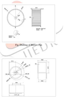
Fig (06): CAD mode Drafting Details of Centrifugal Blower:
1. Blower Impeller:
Fig. Drafting of Blower Fan
Blower Casing:
Fig (08) Drafting of Blower Casing
IJEDR1603141
International Journal of Engineering Development and Research (www.ijedr.org)876
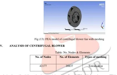
Fig (09) Drafting of Blower Nozzle FEA Model of Centrifugal Blower Fan:
Fig (13): FEA model of centrifugal blower fan with meshing
IV. ANALYSIS OF CENTRIFUGAL BLOWER
Table: No. Nodes & Elements
The analysis of centrifugal blower has been carried out by using ANSYS 14.5 general purpose FEM software. The following analysis is done on the centrifugal blower impeller
1) Static analysis 2) Modal analysis
STATIC ANALYSIS OF CENTRIFUGAL BLOWER FAN:
Procedure For Static Analysis In Ansys:
1. Build the FE model as explained in chapter 4
2. Define the material properties such as young's modulus and density etc., 3. Apply boundary condition and pressures.
4. Solve the problem using current LS command from the tool bar.
ANSYS 14.5:
ANSYS Work bench can be thought of as a software platform or framework where you perform your analysis (Finite Element Analysis) activities. In other words, workbench allows you to organize all your related analysis files and databases under same frame work. Among other things, this means that you can use the same material property set for all your analyses.
The ANSYS Workbench platform allows users to create new, faster processes and to efficiently interact with other tools like CAD systems. In this platform working on Metaphysics simulation is easy. Those performing a structural simulation use a graphical interface (called the ANSYS Workbench Mechanical application) that employs a tree-like navigation structure to define all parts of their simulation: geometry, connections, mesh, loads, boundary conditions and results. By using ANSYS workbench the user can save time in many of the tasks performed during simulation. The bidirectional links with all major CAD systems offer a very efficient way to update CAD geometries along with the design parameters.
Static Analysis For Equivalent (Von-Misses) Stress:
No. of Nodes No. of Elements Types of meshing
IJEDR1603141
International Journal of Engineering Development and Research (www.ijedr.org)877
Static analysis of critical part of centrifugal blower i.e. static analysis of fan is done by using FEA. Fan is core part of centrifugal blower and all the performance of blower is totally depends upon fan, so fan is chosen critical part of centrifugal blower for the static analysis. Analysis is done for the material MS, SS, and SS304L (Food Grade Steel) respectively, in order to check Equivalent stresses and its corresponding deformations induced in each material.Fig (14): Equivalent Stress of MS blower Fan, MPa
Fig (15): Equivalent Stress of SS blower Fan, MPa
Fig (16): Equivalent Stress of SS304L blower Fan, Mpa
Static Analysis for Total Deformation:
IJEDR1603141
International Journal of Engineering Development and Research (www.ijedr.org)878
Fig (18): Total Deformation of SS blower Fan, mmFig (19): Total Deformation of SS304L blower Fan, mm
After modifying Design: Reducing 1 mm thickness of impeller
IJEDR1603141
International Journal of Engineering Development and Research (www.ijedr.org)879
Fig (20): Total Deformation of SS304L blower Fan, by reducing 1mm thicknessVI.RESULT TABLE
Sr.
No. Material
Stress
(MPa) Deformation (mm) Weight (Kg)
1 MS 7.17 0.0429 35.93
2 SS 7.17 0.0412 35.93
3 SS304L 5.90 0.0506 37.89
4 SS304L (Optimized) 6.68 0.0406 33.705
VII.CONCLUSIONS
As MS impeller is replaced by SS304L food grade material corrosion problem is reduced. The maximum deflection induced in metallic blower fan i.e. SS304L material is 0.0406mm, which is in safe limits (1% of total span). Hence based on rigidity the design is safe. The maximum induced stress for the same material is 6.68 Mpa which is less than the allowable stress (110 Mpa).Hence the design is safe based on strength. If we compare corresponding deformation of the material MS, SS on above results SS304L material having minimum deformation therefore there are less chances of failure of the blower fan as compare to other two materials. Hence the strength of blower gets increased because of the SS3104L material. From the above result table it is clear that weight of the SS304L blower fan material is minimum as compared to other material, hence weight of the blower fan optimized.
VIII.ACKNOWLEDGMENT
Thanks to Hindustan Blower Industries to share the details about materials and its assembly process and thanks to Prof. Swami M.C. for their valuable guidance and checking paper.
IX.FUTURE SCOPE
The present work gives only static, modal CFD analysis of critical parts of centrifugal blower in order to optimize the weight & enhance strength of the blower, to reduce vibration problems; also this works provides solution to the corrosion problem by suggesting alternative material. However this project does not gives the Transient and Harmonic analysis of centrifugal blower as the fan is rotating member so it produces vibrations, in future there is scope of harmonic and transient analysis. CFD analysis of the blower fan, using CFD simulation tool in order to increase performance of the given centrifugal blower.
REFERENCES
[1] Static and Dynamic Analysis of a Centrifugal Blower Using FeaVeeranjaneyulu Itha1, T.B.S.Rao2, International Journal of Engineering Research & Technology (IJERT) Vol. 1 Issue 8, October - 2012 ISSN: 2278-0181, pp. 1-11.
[2] Numerical Design and Parametric Optimization of Centrifugal Fans with Airfoil Blade Impellers AtrePranav C. and ThundilKaruppa Raj R. School of Mechanical and Building Sciences, VIT University, Vellore-632014, Tamilnadu, INDIA.
[3] A numerical Study on the Acoustic Characteristics of a Centrifugal Impeller with a Splitter Wan-Ho Jeon1 1 Technical Research Lab., CEDIC Ltd., #1013, Byuksan Digital Valley II, Kasan- dong.
IJEDR1603141
International Journal of Engineering Development and Research (www.ijedr.org)880
[5] Numerical Analysis of Internal Flow Field of Multi- Blade Centrifugal Fan for Floor Standing Air- Conditioner Jia BingWang Huazhong University of Science and Technology.
[6] M. Carudina, “Noise generation in vane axial fans due to rotating stall and surge”, Journal of Mechanical Engineering Science, Volume 215, Number 1, pp. 57-64, 2001
[7] Christopher L. Banks and Sean F. Wu, “Prediction and reduction of centrifugal blower noises” Journal of Acoustical Society of America, Volume 103, Number 5, pp. 3045-3045, May 1998.
[8] Claudia Marcela Méndez, MónicaMarielaCovinich and Alicia Esther Ares, “Resistance to Corrosion and Passivity of 316L Stainless Steel Directionally Solidified Samples” INTECH open Science book